The shrinking instability of toroidal liquid droplets in the Stokes flow regime
Abstract
We analyze the stability and dynamics of toroidal liquid droplets. In addition to the Rayleigh instabilities akin to those of a cylindrical droplet there is a shrinking instability that is unique to the topology of the torus and dominates in the limit that the aspect ratio is near one (fat tori). We first find an analytic expression for the pressure distribution inside the droplet. We then determine the velocity field in the bulk fluid, in the Stokes flow regime, by solving the biharmonic equation for the stream function. The flow pattern in the external fluid is analyzed qualitatively by exploiting symmetries. This elucidates the detailed nature of the shrinking mode and the swelling of the cross-section following from incompressibility. Finally the shrinking rate of fat toroidal droplets is derived by energy conservation.
pacs:
47.20.DrLiquid droplets of various shapes are ubiquitous in nature pure and applied. They are found in rain, clouds, paint, lubricants, inks, dyes and oil deGennes ; Craster and are being increasingly exploited in microfluidics microfluidicRMP . The instabilities of liquid droplets have attracted attention since the beginning of the 19th century Eggers ; ChandraInstability ; sciapplication ; experimentinstability1 ; experimentinstability2 ; experimentinstability3 . Early work of Plateau showed that a long cylindrical liquid droplet is unstable to capillary wave deformations of wavelength exceeding the droplet circumference. Rayleigh subsequently determined the most unstable capillary mode by solving the Navier-Stokes equation Rayleigh ; Rayleigh196 . Purely planar liquid droplets are, in contrast, stable since capillary waves always increase the droplet surface area and hence the free energy Safran . Droplet instabilities thus probe the combined influence of the three-dimensional geometry of the droplets and their surface tension Eggers .
In this paper we study the instability of liquid droplets in the form of three-dimensional axially symmetric solid tori, inspired by recent experiments in which bulk liquid tori are created by extruding water or glycerin through a metallic needle into a rotating bath of viscous silicone oil Pairam . Thin toroidal droplets exhibit Rayleigh instabilities analogous to those of the cylinder Rayleigh ; Tomotika ; McGraw , with the additional requirement that the most unstable mode has wavelength commensurate with the outer circumference of the torus. When the outer circumference is an integer (n) times , the toroidal droplet eventually fissions into n solid spherical droplets (three-dimensional balls). Thus the change in topology of the droplet (solid torus breaks up into n balls) is governed by a Bohr quantization condition with the final number of balls playing the role of the principal quantum number n. Toroidal droplets also exhibit a fundamentally different type of instability in which the torus shrinks to close its interior hole, eventually becoming a single ball. This instability is a signature of the topological character of the torus and does not exist for a cylinder. Although it is present for a torus of any aspect ratio, it is preempted by the Rayleigh instability unless the torus is sufficiently fat (see Appendix B).
The outline of this paper is as follows: we first analyze the shrinking instability of toroidal droplets by minimizing a free energy controlled by interfacial surface tension. We then derive the pressure distribution driving bulk flow of the fluid. The shrinking mode is then examined in more depth via the Stokes equation, which is the large Ohnesorge number () limit of the Navier-Stokes equation. The biharmonic equation for the stream function determines the velocity field inside the toroidal liquid droplet. The shrinking of the droplet and simultaneous swelling of the cross-section from volume conservation are clearly revealed in the flow. Finally, we calculate the shrinking speed by balancing the rate of free energy gain with the viscous dissipation rate.
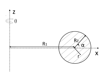
A three-dimensional axially symmetric solid torus is characterized by coordinates , as shown in Fig.1. Here is the angle around the tube, is the azimuthal angle around the z-axis, and is the radial coordinate of the tube. The central circle of the solid torus with radius (at ) will be called the reference circle of the solid torus. The outer radius of the tube is denoted . The aspect ratio of the toroidal surface is then . The non-zero components of the metric tensor of the solid torus are and .
The instability of a toroidal liquid droplet to shrinking can be seen in terms of the free energy . In the shrinking process, decreases and increases due to volume conservation. The change of free energy with radius is
| (1) |
Thus toroidal liquid droplets shrink to reduce the free energy. Although this static analysis reveals the shrinking mode, the free energy alone does not provide a complete description of the system. In particular, determining the shrinking rate requires a study of droplet hydrodynamics.
We first analyze the pressure distribution in a toroidal droplet to understand the driving force for bulk flow. Taking the divergence of the Navier-Stokes equation for an incompressible fluid shows that the pressure must be harmonic
| (2) |
The boundary condition is given by the distribution of Laplace pressure on the interface between the inner and outer fluids
| (3) |
where H is the mean curvature . For simplicity, we first consider the external pressure as constant. The problem of solving for the pressure distribution in the bulk fluid is then reduced to solving Laplace’s equation, Eq.(2), with the specified boundary condition. The Laplace pressure drop from the exterior () to the interior () of the torus is given by and is a measure of the asymmetry of the torus. Since , the Laplace pressure on the exterior of the toroid is always bigger than on the interior. One also sees that the asymmetry is more pronounced for a fat torus with aspect ratio approaching one. In the limit , a toroid approaches a solid cylinder and the asymmetry as well as the shrinking mode disappear. Note that for the opposite case of constant pressure in the inner fluid, the pressure in the outer fluid will fall from the interior to the exterior of the torus. The outer fluid will therefore flow outward and the inner fluid will correspondingly flow inward, shrinking the droplet. Shrinking is thus a universal feature of one toroidal fluid inside another.
Laplace’s equation for the pressure Eq.(2) separates in the coordinates torusgeometry1 ; EMbooktorus defined by
where .
Exploiting azimuthal symmetry and imposing the requirement that the pressure be finite as one approaches the reference circle, the physically acceptable solution takes the form EMbooktorus
| (4) |
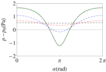
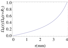
where is the real part of the associated Legendre function of the second kind. The coefficients can be determined by imposing the boundary condition in Eq.(3). The pressure distribution inside the droplet is plotted in Fig.2 for aspect ratio , surface tension and . The pressure clearly drops from the exterior () to the interior (). This pressure gradient drives the fluid towards the center of the toroid. As decreases the pressure distribution becomes more isotropic (-independent). Note that only the mode in Eq.(4) contributes to the pressure near the reference circle. This enables us to study the behavior of the fluid near the reference circle analytically. By inserting the zero mode in Eq.(4) into the Stokes equation one can determine the velocity field near the reference circle in coordinates: , and . The velocity field near the reference circle is uniform towards the center of the toroid.
We now turn to the velocity distribution in a viscous toroidal liquid droplet. In this regime of large Ohnesorge number the Navier-Stokes equation reduces to the Stokes equation
| (5) |
where is the fluid viscosity. Here viscous dissipation dominates over kinetic energy damping:
| (6) |
where is the viscous stress tensor. Since the characteristic speed of the fluid is much smaller than the speed of sound, we can treat the fluid as incompressible ()Landau . For incompressible fluids one can write the velocity field as the curl of a vector potential () leading directly to
| (7) |
The complete velocity field can be obtained by solving the biharmonic vectorial equation Eq.(7) which reduces to a simplified scalar differential equation in the coordinatesE4paperbiharmonic
| (8) |
where , the stream function, is the only non-zero component of the vector potential and the second-order partial differential operator is given by , with and . Imposing the physical requirements that approaching the reference circle tends to a finite value and (reflection symmetry) yields the complete solution
| (9) |
Note that and as (). Thus only the mode contributes to the flow near the reference circle. The coefficients in Eq.(9) can be determined by matching to the velocity field on the interface. Assuming that high viscosity fixes the fluid particles on the interface to move with the interface as it shrinks, the boundary conditions are found to be and , where and denote spatial points on the boundary and . The point is the center of the cross section. The mode is sufficient to fit this boundary condition.
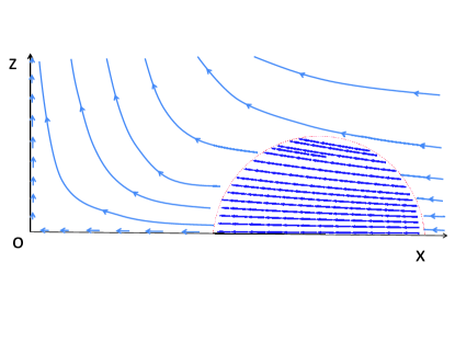
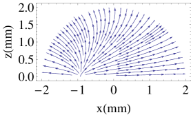
The velocity field inside the droplet in the laboratory frame is plotted in Fig.3. The shrinking of the droplet is clearly indicated by the inward directed flow inside the droplet. One also sees that outer fluid within the toroidal hole is squeezed out. Further insight is provided by plotting the velocity field (see Fig.4) inside the droplet in a reference frame comoving with the shrinking of the droplet. The swelling of the cross section resulting from volume conservation is clearly visible.
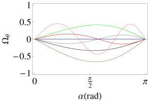
The vorticity field, is plotted in Fig.5 which shows its only non-zero component as a function of and respectively. Fig.5(a) shows that the vorticity field is only significant near the boundary – it decays rapidly as one approaches the reference circle. Fig.5(b) shows versus for . The vorticity field vanishes at and due to its odd parity. The sign of reflects the chiral property of vortices. The number of peaks and valleys on the plane (i.e., ) is
and is therefore completely determined by the mode .
In the process of shrinking the free energy gained is dissipated in viscous damping. By equating the rate of change of the free energy, Eq.(1), to the viscous dissipation rate we can obtain the shrinking speed. We focus here on the experimentally explored case of a low viscosity () inner fluid immersed in a viscous () outer bath Pairam . In this case the dissipation occurs almost entirely in the outer fluid. Applying Stokes’ equation for an incompressible fluid the dissipation rate can be separated into two parts
| (10) | |||
Here is the component of the area element of the interface. The first term is the heat flux on the fluid boundary and the second term is the dissipation rate inside the bulk fluid. The second term can be related to the vorticity: . Since the Reynolds number of the external fluid is very small in the experimental setup ( Pairam ), we may take the external flow to be as irrotational (vanishing vorticity) by recalling the experiment of flow through a cylindrical solid: an irrotational-rotational flow transition occurs at , below which the flow is irrotational Feynman . In the shrinking process, the toroidal droplet moves in the external fluid. This is equivalent to flow through the toroidal droplet. Since the viscosity of the internal fluid is very small in this case, the internal dissipation can be neglected. Thus we need to calculate only the surface integral in Eq.(10) to obtain the dissipation rate. We need the viscous stress on the boundary to evaluate the surface integral. Rotational symmetry and the limiting condition imply both and vanish at the interface. To determine we need the gradient of at the interface. Assuming that the fluid particles near the boundary move together with the interface during shrinking, as a result of the viscous external fluid, we have
| (11) |
Inserting Eq.(11) along with the velocity field on the interface into the surface term of Eq.(10) yields
| (12) |

By equating the rate of change of the free energy from Eq.(1) and the dissipation rate Eq.(12), we have
| (13) |
and the interior hole of the droplet decreases in size according to
| (14) |
where and . The shrinking speed is controlled by the aspect ratio of the droplet, in accord with experimental observations Pairam . In the limit of infinite aspect ratio (the cylinder) the shrinking speed vanishes, as required. The constant in the denominator of Eq.(13) plays an important role in the limit that the aspect ratio approaches one (fat tori). The plot of versus is shown in Fig.6 for an initial aspect ratio , , , and . For these parameters . Fig.6 shows that droplets shrink with roughly constant speed, as found in Pairam . Our results predict that it would take about (aspect ratio ) and (aspect ratio ) for a toroidal droplet to shrink to close the inner hole of toroid, in qualitative agreement with the experimental values of and respectively. Thus thinner toroidal droplets shrink more slowly, consistent with experimental observations Pairam .
Our energy conservation approach to determining the shrinking speed can also be applied to a 2-dimensional system where it yields an analytical result. Consider a shrinking hole on a liquid film. The limiting case of a shrinking toroidal liquid droplet with and can be modelled as such a 2-dimensional system, since the dynamics of the hole becomes independent of the fluid far away from the hole. As the hole shrinks, a flow will be induced outside the hole on the film. In the Stokes flow regime, the velocity field can be derived analytically in the polar coordinates as and . By energy conservation, the shrinking speed of the hole can also be derived analytically. By equating the rate of change of the line energy and the viscous dissipation rate , we have , where is the viscosity of fluid and is the line tension.
We expect that the formalism employed here will have a variety of applications to the dynamics of fluid interfaces. It may also be extended to liquid crystalline droplets where the interplay of liquid crystalline order and the shape of the droplet should be very rich.
Acknowledgements
We thank Xiangjun Xing for extensive discussions and Alberto Fernández-Nieves for introducing us to his beautiful experiments on toroidal droplets. This work was supported by the National Science Foundation grant DMR-0808812 and by funds from Syracuse University.
Appendix
.1 The shape of cross section
So far we have assumed that droplets remain perfectly circular in cross-section as they shrink. Here we show that this assumption is well justified.


The shape of a toroidal liquid droplet is characterized by the radii and which may in general vary with and . Retaining azimuthal symmetry we consider the following ansatz for at a fixed time:
| (.1.1) |
The second term describes an ellipse which is symmetric about z axis, while the third term describes a shape with three round corners, which is asymmetric about the z-axis (we are ignoring the shrinking mode here, described by a term). The shape of the droplet is specified by points in the space.
We numerically search for the ground state in the space for which
| (.1.2) |
is minimized, where and are the volume and surface area of the unperturbed droplet. is set to be large to impose volume conservation. We take and .
.2 Rayleigh instability vs shrinking mode
It is observed experimentallyPairam that the Rayleigh instability disappears for sufficiently fat solid tori () whereas the shrinking mode is present for all aspect ratios. Here we derive a lower bound on the aspect ratio for the emergence of the Rayleigh instability.
Two conditions must be satisfied for the Rayleigh instability: (1) modes with wavelength , where is the minimum wavelength of the Rayleigh instability mode and (2):
| (.2.1) |
where is the perturbation amplitude and is the lifetime of the shrinking droplet (). It is well known Rayleigh ; Rayleigh196 that grows exponentially:
| (.2.2) |
where is the characteristic speed and the characteristic length scale of the system. We assume that grows exponentially all the way until breakup of the droplet. On the other hand we have shown that decreases almost linearly in time. So formally, we have
| (.2.3) |
from which we have . By inserting Eq.(.2.2,.2.3) into Eq.(.2.1), we obtain
| (.2.4) |
where is an aspect ratio factor of order one that tends to for aspect ratio one by Eq.(14). Thus the Rayleigh instability is dominant for sufficiently thin tori.
It can be checked that for aspect ratios satisfying Eq.(.2.4) even the perimeter of the interior of the torus () can accommodate the Rayleigh instability mode, i.e.,
| (.2.5) |
References
References
- (1) P.G. de Gennes, F. Brochard-Wyart, and D. Quéré, Capillarity and Wetting Phenomena:Drops, Bubbles, Pearls, Waves (Springer, New York, 2003).
- (2) R.V. Craster and O.K. Matar, Rev.Mod. Phys. 81, 1131 (2009).
- (3) T.M. Squires and S.R. Quake, Rev. Mod. Phys. 77, 977 (2005).
- (4) J. Eggers, Rev. Mod. Phys. 69, 865 (1997).
- (5) S. Chandrasekhar, Hydrodynamic and Hydromagnetic Stability (Clarendon Press, Oxford, 1961).
- (6) M. Moseler and U. Landman, Science 289, 1165 (2000).
- (7) E.F. Goedde and M.C. Yuen, J. Fluid Mech. 40, 495 (1970).
- (8) H. Teng, C.M. Kinoshita, and S.M. Masutani, Int. J. Multiphase Flow 21, 129 (1995).
- (9) R.J. Donnelly and W. Glaberson, Proc. R. Soc. London, Ser. A 290, 547 (1966).
- (10) L. Rayleigh, Philos. Mag. XXXIV, 145 (1892).
- (11) L. Rayleigh, Philos. Mag. XXXIV, 177 (1892).
- (12) S.A. Safran, Statistical Thermodynamics of Surfaces, Interfaces and Membranes (Westview Press, Boulder, 2003).
- (13) E. Pairam and A. Fernández-Nieves, Phys. Rev. Lett. 102, 234501 (2009).
- (14) S. Tomotika, Proc. R. Soc. London, Ser. A 150, 322 (1935).
- (15) J.D. McGraw et al., Soft Matter 6, 1258 (2010).
- (16) M. Bowick, D.R. Nelson, and A. Travesset, Phys. Rev. E 69, 041102 (2004).
- (17) J. Vanderlinde, Classical Electromagnetic Theory, 2nd edition (Kluwer Academic Publisher, Dordrecht, 2004).
- (18) L.D. Landau and E.M. Lifshitz, Fluid Mechanics, 2nd edition (Pergamon Press, Oxford, 1987).
- (19) S.A. Khuri and A.M. Wazwaz, Appl. Math. Comput. 85, 139 (1997).
- (20) R.P. Feynman, R.B. Leighton, and M. Sands, The Feynman Lectures on Physics, Volume 2 (Addison-Wesley Publishing Company, Massachusetts, 1964).