Tunable subpicosecond electron bunch train generation
using a transverse-to-longitudinal phase space exchange technique
Abstract
We report on the experimental generation of a train of subpicosecond electron bunches. The bunch train generation is accomplished using a beamline capable of exchanging the coordinates between the horizontal and longitudinal degrees of freedom. An initial beam consisting of a set of horizontally-separated beamlets is converted into a train of bunches temporally separated with tunable bunch duration and separation. The experiment reported in this Letter unambiguously demonstrates the conversion process and its versatility.
pacs:
29.27.-a, 41.85.-p, 41.75.FrRecent applications of electron accelerators have spurred the demand for precise phase-space control schemes. In particular, electron bunches with a well-defined temporal distribution are often desired. An interesting class of temporal distribution consists of trains of bunches with subpicosecond duration and separation. Applications of such trains include the generation of super-radiant radiation gover ; bosco ; ychuang and the resonant excitation of wakefields in novel beam-driven acceleration methods muggliprstab ; jing . To date there are very few methods capable of providing this class of beams reliably muggli . We have recently explored an alternative technique based on the use of a transverse-to-longitudinal phase space exchange method piotAAC08 ; yineLINAC08 . The method consists of shaping the beam’s transverse density to produce the desired horizontal profile, the horizontal profile is then mapped onto the longitudinal profile by a beamline capable of exchanging the phase spaces between the horizontal and longitudinal degrees of freedom. Therefore the production of a train of bunches simply relies on generating a set of horizontally-separated beamlets upstream of the beamline, e.g., using a masking technique. Considering an electron with coordinates (here , are respectively the horizontal and longitudinal momenta, represents the average longitudinal momentum) in the four dimensional trace space, the transfer matrix associated to an ideal transverse-to-longitudinal phase-space-exchanging beamline is -block anti-diagonal. Thus the beamline exchanges the emittances between the transverse and longitudinal degrees of freedom. The normalized horizontal root-mean-square (rms) emittance is defined as , where is the Lorentz factor and . A similar definition holds for the longitudinal degree of freedom. Phase-space-exchanging [or emittance-exchanging (EEX)] beamlines were initially considered as a means to increase the luminosity in the B-factories orlov , mitigate instabilities in high-brightness electron beams emma , and improve the performance of single-pass free-electron lasers emma2 .
A simple configuration capable of performing such a phase-space exchange consists of a horizontally-deflecting resonant cavity, operating in the TM110 mode, flanked by two horizontally-dispersive sections henceforth referred to as “doglegs” kim . Describing the beamline elements with their thin-lens-matrix approximation, an electron with initial trace space coordinates will have its final coordinates . In particular the electron’s final longitudinal coordinates are solely functions of its initial transverse coordinates yine
| (3) |
where is the distance between the dogleg’s dipoles, and and are respectively the horizontal and longitudinal dispersions generated by one dogleg. Here the deflecting cavity is operated at the zero-crossing phase, i.e., the center of the bunch is not affected while the head and tail are horizontally deflected in opposite directions. The deflecting strength of the cavity where is the electron charge, is the wavelength of the TM110 mode, and is the integrated maximum deflecting voltage, is chosen as . The coupling described by Eq. 3 can be used to arbitrarily shape the current or energy profile of an electron beam piotPRSTAB .
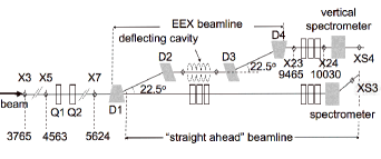
The experiment reported in this Letter uses the -MeV electron bunches produced by a radiofrequency (rf) photoemission electron source and accelerated in an rf superconducting cavity at Fermilab’s A0 Photoinjector carneiro . Downstream of the cavity, the beamline includes a set of quadrupole and steering dipole magnets, and beam diagnostics stations before splitting into two beamlines as shown in Fig. 1.
The “straight ahead” beamline incorporates a horizontally-bending spectrometer equipped with a Cerium-doped Yttrium Aluminum Garnet (Ce:YAG) scintillating screen (labeled as XS3 in Fig. 1) to measure the beam’s energy distribution. The horizontal dispersion at the XS3 location is mm.
| Parameter | Symbol | Value | Units |
|---|---|---|---|
| energy | 14.3 0.1 | MeV | |
| charge | pC | ||
| rms duration | 4.0 0.3 | ps | |
| horizontal emit. | m | ||
| rms frac. energy spread | 0.06 0.01 | % | |
| horizontal C-S param. | (,) | (–,m) |
The other beamline, referred to as the EEX beamline, implements the double-dogleg setup described above koeth0 and has been used to explore emittance exchange amber . The doglegs consist of dipole magnets with bending angles and each generates horizontal and longitudinal dispersion of cm and cm, respectively footnote . The deflecting cavity is a liquid-Nitrogen–cooled five-cell copper cavity operating on the TM110 -mode at 3.9 GHz koeth . The section downstream of the EEX beamline includes three quadrupoles, beam diagnostics stations and a vertical spectrometer. The dispersion generated by the spectrometer at the XS4 Ce:YAG screen is mm. The temporal distribution of the electron bunch is diagnosed via the coherent transition radiation (CTR) transmitted through a single-crystal quartz window as the beam impinges an aluminum foil at X24. The CTR is sent through a Michelson autocorrelator tr and the autocorrelation function is measured by a liquid helium-cooled bolometer which is used as the detector of the autocorrelator. The CTR spectrum is representative of the bunch temporal distribution provided where and are respectively the rms bunch length and transverse size at the CTR radiator location (the beam is assumed to be cylindrically symmetric at this location). In the present experiment the beam was focused to an rms spot size of m at X24. Imperfections due to the frequency-dependent transmissions of the THz beamline components alter the spectrum of the detected CTR and limit the resolution to fs.
For the proof-of-principle experiment reported here, a number of horizontally-separated beamlets were generated by passing the beam through a set of vertical slits at X3. The measured parameters for the incoming beam are gathered in Table 1. The multislit mask, nominally designed for single-shot transverse emittance measurements, consists of 48 m-wide slits made out of a 3-mm-thick tungsten plate. The slits are separated by 1 mm. Less than 5 % of the incoming beam is transmitted through the mask. Up to 50 electron bunches repeated at 1 MHz were used to increase the signal-to-noise ratio of the measurements.
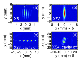
The beam was first diagnosed in the straight-ahead line to ensure that horizontal modulations are clearly present and there are no energy modulations [Fig. 2 (a) and (b)]. It was then transported through the EEX beamline with the deflecting cavity turned off. The transverse modulation was still observable at X23 but no energy modulation could be seen at XS4 as shown in Fig. 2 (c), (d), (g) and (h). Powering the cavity to its nominal deflecting voltage ( kV) resulted in the suppression of the transverse modulation at X23 and the appearance of an energy modulation at XS4 [Fig. 2 (e), (f), (g) and (h)]. These observations clearly demonstrate the ability of the EEX beamline to convert an incoming transverse density modulation into an energy modulation. In the present measurement the incoming horizontal Courant-Snyder (C-S) parameters at the EEX beamline entrance were empirically tuned for energy and time modulation in the beam by setting the current of quadrupole magnets and to respectively 1.6 A and -0.6 A.
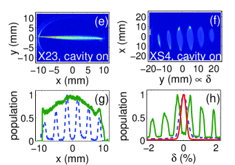
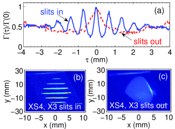
To characterize the expected temporal modulations we detect and analyze the CTR emitted as the beam impinges the X24 aluminum foil saxon . The total CTR energy detected within the detector bandwidth and angular acceptance increases as the bunch duration decreases. In the limit , the total radiated energy is inversely proportional to the rms bunch duration piotvelo . The final longitudinal C-S parameters downstream of the EEX beamline can be varied by altering the initial horizontal C-S parameters using the quadrupole magnets and . Figure 3 shows the detected CTR energy as a function of quadrupole magnet currents for the cases without (a) and with (b) intercepting the beam with the X3 multislit mask. The two plots illustrate the ability to control the final bunch length (as monitored by the CTR power detected at X24) using the EEX technique. The insertion of the multislit mask results in the appearance of a small island of coherent radiation at the lower right corner of Fig. 3 (b). The corresponding autocorrelation functions (where is the optical path difference) recorded by the bolometer for the quadrupole magnets currents (1.6 A,-0.6 A) are shown in Fig. 4 (a) with and without inserting the multislit mask. When the multislit mask is inserted the autocorrelation function is multipeaked indicating a train of bunches is produced. For this particular case a train of bunches with unequal peak intensity are produced resulting in an autocorrelation function with peaks. The measured separation between the bunches is m. It should be noted that the two autocorrelations shown in Fig. 4 correspond to very different charges and longitudinal space charge effects influence the bunch dynamics and result in different final longitudinal C-S parameters. In addition, the low frequency limit of the CTR detection system prevents the accurate measurement of autocorrelation functions of bunches with rms length larger than m TimM .
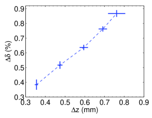
In addition, varying the settings of the quadrupole magnets provide control over the final longitudinal phase space time-energy correlation. The correlation can be measured as the ratio of the peak separation along the longitudinal coordinate and the energy . These measurements are presented in Fig. 5 for different quadrupole magnet settings. As shown in Fig. 5, the technique can provide a tunable bunch spacing ranging from to m given an initial slit spacing of 1 mm by adjusting one quadrupole magnet strength (Q1) only. For m (corresponding to ps), the autocorrelation has a 100% modulation implying that the bunches within the train are fully separated. Assuming the bunches follow a Gaussian distribution, their estimated rms duration is fs (this estimate includes the finite resolution of our diagnostics). Variation of both Q1 and Q2 quadrupole magnet strengths can generate even shorter bunch separations, however our current measurement system has limited sensitivity in the shorter wavelength region, resulting in less than 100% modulation in the autocorrelation curve.
In summary we have experimentally demonstrated that an incoming phase space modulation in the horizontal coordinate can be converted into the longitudinal phase space using an EEX beamline. The method was shown to produce energy- and time-modulated bunches arranged as a train of subpicosecond bunches with variable spacing. This proof-of-principle experiment also provides an unambiguous demonstration of the main property of the EEX beamline to exchange the phase space coordinates between the horizontal and longitudinal degrees of freedom. The technique experimentally demonstrated in this Letter can be used to tailor the current and energy profile of electron beams and could have applications in novel beam-driven acceleration techniques, compact short-wavelength accelerator-based light sources, and ultra-fast electron diffraction.
We are indebted to E. Harms, E. Lopez, R. Montiel, W. Muranyi, J. Santucci, C. Tan and B. Tennis for their technical supports. We thank M. Church, H. Edwards, and V. Shiltsev for their interest and encouragement. The work was supported by the Fermi Research Alliance, LLC under the U.S. Department of Energy Contract No. DE-AC02-07CH11359, and by Northern Illinois University under the US Department of Energy Contract No. DE-FG02-08ER41532.
References
- (1) A. Gover, Phys. Rev. ST Accel. Beams 8, 030701 (2005).
- (2) M. Bolosco, I. Boscolo, F. Castelli, S. Cialdi, M. Ferrario, V. Petrillo and C. Vaccarezza, Nucl. Instr. Meth. A 577, 409 (2007).
- (3) Y.-C. Huang, Int. Jour. Mod. Phys. B 21, 287 (2007).
- (4) P. Muggli, B. Allen, V. E. Yakimenko, J. Park, M. Babzien, K. P. Kusche, and W. D. Kimura, Phys. Rev. ST Accel. Beams 13, 052803 (2010).
- (5) C. Jing, A. Kanareykin, J. G. Power, M. Conde, Z. Yusof, P. Schoessow, and W. Gai, Phys. Rev. Lett. 98, 144801 (2007).
- (6) P. Muggli, V. Yakimenko, M. Babzien, E. K. Kallos, K. P. Kusche, Phys. Rev. Lett. 101, 054801 (2008).
- (7) P. Piot, Y.-E Sun, and M. Rihaoui, Proceedings of the 13th Advanced Accelerator Concept workshop (AAC08), AIP Conf. Proc. 1086, 677 (2009).
- (8) Y.-E Sun, and P. Piot, Proceedings of the 2008 International Linac Conference (LINAC08), Victoria BC, 498 (2009).
- (9) Y. Orlov, C. M. O’Neill, J. J. Welch, and R. Sieman, Proceedings of the 1991 Particle Accelerator Conference (PAC91), San Francisco CA, 2838 (1991).
- (10) M. Cornacchia, and P. Emma, Phys. Rev. ST Accel. Beams 5 084001 (2002).
- (11) P. Emma, Z. Huang, K.-J. Kim, and P. Piot, Phys. Rev. ST Accel. Beams 9, 100702 (2006).
- (12) K.-J. Kim and A. Sessler, Proceedings of the 2006 Electron Cooling Workshop, Galena IL (ECOOL06), AIP Conf. Proc. 821, 115 (2006).
- (13) Y.-E Sun, et al, Proceedings of the 2007 Particle Accelerator Conference, Albuquerque NM (PAC07), 3441 (2007).
- (14) P. Piot, et al., submitted to Phys. Rev. ST Accel. Beams (2010); see electronic preprint arXiv:1007.4499v1 (2010).
- (15) J.-P. Carneiro, et al., Phys. Rev. ST Accel. Beams 8, 040101 (2005).
- (16) T. Koeth, et al, Proceedings of the 2009 Particle Accelerator Conference, Vancouver BC (PAC09), FR5PFP020 (2009).
- (17) A. Johnson, et al., Proceedings of the 2010 International Particle Accelerator Conference, Kyoto Japan (IPAC10), 4614 (2010).
- (18) In our convention, the head of the bunch is for .
- (19) T. Koeth, et al, ibid yine , 3663 (2007).
- (20) U. Happek, A. J. Sievers, and E. B. Blum, Phys. Rev. Lett. 67, 2962 (1991).
- (21) J. S. Nodvick and D. S. Saxon, Phys. Rev. 96, 180 (1954).
- (22) P. Piot, L. Carr, W. S. Graves, and H. Loos, Phys. Rev. ST Accel. Beams 6, 033503 (2003).
- (23) T. J. Maxwell, D. Mihalcea and P. Piot, Proceedings of the 13th Beam Instrumentation Workshop (BIW08), Tahoe City CA, 225 (2008).