A High-Resolution Survey of HI Absorption toward the Central 200 pc of the Galactic Center
Abstract
We present an HI absorption survey of the central 250 pc of the Galaxy. Very Large Array (VLA) observations were made at 21 cm in the DnC and CnB configurations and have a resolution of 15”(0.6 pc at the Galactic Center (GC) distance) and a velocity resolution of 2.5 km s-1. This study provides HI data with high spatial resolution, comparable with the many high resolution observations which have been made of GC sources over the past ten years. Here we present an overview of the HI absorption toward 40 well-known continuum sources and a detailed comparison of the ionized, atomic and molecular components of the interstellar medium for the Sgr B, Radio Arc and Sgr C regions. In these well-known regions, the atomic gas appears to be closely correlated in both velocity and distribution to the ionized and molecular gas, indicating that it resides in photo-dissociation regions related to the HII regions in the GC. Toward the majority of the radio continuum sources, HI absorption by the 3-kpc arm is detected, constraining these sources to lie beyond a 5 kpc distance in the Galaxy.
1 Introduction
The bright and unusual radio continuum sources in the central few hundred pc of the Galaxy provide an opportunity to observe the 21 cm line of atomic hydrogen in absorption. Previous HI absorption studies toward the Galactic center (GC) have been crucial in the understanding of Galactic structure and rotation and the nature of atomic gas in the inner parts of the Galaxy (e.g., Schwarz, Shaver & Ekers 1977; Radhakrishnan & Sarma 1980; Schwarz, Ekers & Goss 1982; Liszt et al. 1983, 1985). There are several well-known HI components in the direction of the GC (Cohen & Davies 1979): (1) the expanding 3 kpc arm appears at v=53 km s-1 and is thought to be 5.5 kpc from the Sun, (2) HI components near v=+135 km s-1 are thought to be beyond the GC by distances of a few hundred parsecs to 2 kpc, and (3) the “nuclear disk” and “molecular ring” components appearing at velocities of 160 to 200 km s-1 and 135 km s-1 are located within a few hundred parsecs of the GC.
In the inner Galaxy, atomic gas is most often associated with regions of molecular gas where it serves to shield the molecular gas against photodissociation (Dickey & Lockman 1990). Therefore, HI absorption features not described above may be identified with known GC molecular emission features using correlations in velocity structure. The CO survey carried out by Oka et al. (1998) using the Nobeyama 45-m telescope provides the most favorable resolution, velocity, and spatial coverage of any survey of molecular gas within the central Galaxy. In addition, the multitude of “forbidden” (e.g. sign opposite to galactic rotation) velocity components in the GC region are thought to represent the response of the molecular gas in the GC to the Galaxy’s strong stellar bar (Binney et al. 1991; Bally et al. 1988).
The CO survey data of Oka et al. (1998) illustrated that the molecular gas traced by CO emission in the central 200 pc is organized into filamentary and shell-like features. This morphology and kinetic structure indicates that violent kinetic activity (such as supernova explosions and stellar winds from Wolf-Rayet type stars) plays an important role in shaping the ISM. In addition to the Radio Arc region (where the Quintuplet and Arches clusters are located), the GC region is filled with sites where compact thermal radio and mid-infrared sources have been observed (e.g. Sgr B, Sgr C, and at many positions along the Galactic plane; e.g., LaRosa et al. 2000; Egan et al. 1998) and it is likely that massive stars are either forming or have formed in these regions. In addition, the spectrum of diffuse X-ray emission in this region suggests that the ISM is being strongly influenced by massive star-forming activities (Wang, Gotthelf & Lang 2002; Wang, Dong & Lang 2006).
HI absorption toward the bright SgrA complex and the compact SgrA∗ radio source has been the subject of a number of interferometric studies over the last three decades (Radhakrishnan et al. 1972, Schwarz, Ekers & Goss 1982, Liszt et al. 1983; Dwarakanath et al. 2004). These studies illustrate the wide variety of absorption and emission features toward this complex area of the Galaxy, many of which have velocities that indicate non-circular motions. On larger scales, Lasenby, Lasenby & Yusef-Zadeh (1989) carried out the first VLA compact configuration HI absorption study toward the central 30′ of the GC (corresponding to 75 pc at a distance of 8 kpc (Reid et al. 1993)), centered on the well-known Radio Arc nonthermal filaments and including the bright SgrA complex. The spatial resolution was 50-70″ with a velocity resolution of 10.2 km s-1, with a total velocity coverage of 660 km s-1. However, this spatial resolution of the Lasenby et al. (1989) data is not adequate for detailed comparisons with higher frequency continuum and recombination line datasets of the HII regions in the Radio Arc (e.g., Lang et al. 1997, 2001) and velocity information on the ionizing stellar clusters. In addition, the spatial coverage did not include the active Sgr B region. Although high spatial resolution VLA HI absorption measurements have been made toward several individual GC sources (e.g., Uchida et al. (1992) and Roy et al. (2003)), a complete HI absorption study is missing from the growing canon of GC surveys.
Therefore, we have carried out an HI absorption survey of the central 100′ 50′ (250 x 125 pc) of the GC in order (1) to understand the physical arrangement and interactions between the stellar and interstellar components, (2) to place constraints on distances to radio continuum features in the field of view, and (3) to make detailed images and estimates of the HI opacity toward well-studied GC sources. This current HI absorption survey represents the highest resolution and most complete study of HI absorption toward the GC, and forms the basis for understanding the physical line-of-sight locations and interactions between interstellar features in the GC. The 15″ spatial resolution and a velocity resolution 2.5 km s-1 are a vast improvement over the previous HI absorption studies. In 2 we present a summary of the observations and imaging techniques used to produce the images, in 3, we present the results and discussion of this HI absorption study.
2 Observations & Imaging
We have observed at 1.4 GHz (21 cm) using the Very Large Array (VLA) of the National Radio Astronomy Observatory111The National Radio Astronomy Observatory is a facility of the National Science Foundation operated under cooperative agreement by Associated Universities, Inc. in the DnC and CnB array configurations. The observational details are summarized in Tables 1 and 2. In order to cover the 100′50′ area, five fields were observed. The total bandwidth is 1.5 MHz and there are 127 channels used, corresponding to 300 km s-1 in velocity coverage. The observations are centered at 0 km s-1, and have a velocity resolution of 2.5 km s-1. The data were calibrated using the standard AIPS routines.
The line-free channels (channels 10-26) were used to fit a constant continuum level, and continuum subtraction was performed using the AIPS task UVLSF. The data were deconvolved jointly using the miriad software package to take full advantage of the additional sensitivity from overlapping fields. The continuum mosaic was imaged using mosmem, and each plane of the HI absorption cube was cleaned to a uniform rms level using mossdi in miriad. The final spatial resolution of both the continuum and HI absorption line images is 15″. The integration time was 8 hours for the set of five fields in each configuration (i.e., approximately 2.5 hours on each field) which resulted in an rms level of 3-4 mJy beam-1 in the continuum image. The zero level in the continuum image is within 1 (10 mJy) of zero, and the image has also been corrected for the variable system temperature with frequency in the presence of HI emission. The rms noise level in the line images varies between 5-15 mJy beam-1.
3 Results and Discussion
3.1 1.4 GHz Continuum
Figure 1 shows the continuum image constructed from 16 line-free channels at 1.4 GHz. This image is one of the highest-resolution images to date of the more extended structures in the complex GC region, with excellent sensitivity to both point-like and diffuse features. Figure 2 is a contour version of the continuum image in Figure 1, with the major GC sources labeled. In addition, twenty-eight sources have been detected in this image and are listed in Table 3. These sources are categorized as ’compact’ or ’extended’ and for each source, the position, peak intensity, integrated flux density (if resolved), major axes (if resolved), and geometric size (square root of major minor axis) are given. These parameters were obtained by fitting the sources with Gaussian profiles using JMFIT in AIPS. Of the 28 continuum sources detected, 16 are classifed as ’compact’ and 12 as ’extended’. Four of the sources (G0.60-0.20, G0.48+0.07, G0.32-0.19 and G359.87+0.18) are unresolved and likely to be point sources. We also searched the compact source catalogs of Yusef-Zadeh et al. (2004) at 1.4 GHz and Becker et al. (1994) at 4.9 GHz in order to identify counterparts. Sixteen sources in our image that have counterparts in one of these two catalogs are listed in Table 4 with their flux density from our image (1.4-Lang), Yusef-Zadeh et al. (2004; 1.4-FYZ) and Becker et al. (1994; 5-Becker).
3.2 HI Absorption Overview Profiles
Continuum-weighted, line-to-continuum HI absorption integrated spectra were produced towards 40 of the brightest continuum sources in the field. The profiles were made to characterize the HI absorption features toward these well-known sources. In very crowded regions, (e.g., the HII regions in the Radio Arc region and SgrA East and West) the AIPS task BLANK was used interactively to select the region of interest using a signal-to-noise cut off in the continuum image. The GIPSY task profil was used to produce integrated, continuum-weighted, line-to-continuum spectra towards each of the 40 continuum features (van der Hulst et al. 1992). A continuum cutoff of 5 was used in profil to obtain optimal signal-to-noise in the integrated spectra. Since the rms noise varies across the mosaic, a value for was determined locally for each object. Typical rms noise for the spectra are in the range of 0.01-0.05, where the units are line-to-continuum ratio. These profiles were then converted to profiles of optical depth using the formula =-ln(1+(L/C)), where L/C represents the line-to-continuum profile integrated over a region. Multiple Gaussian fits were applied to each of the profiles (using the GIPSY task xgauprof), and Table 5 lists the parameters of the resulting fits and errors when they can be reliably determined (central velocity (vLSR), full-width half maximum line width (VFWHM), and peak opacity HI). A number of the HI components toward the Sgr B and Sgr A complexes are highly saturated. Saturated channels will have an undefined optical depth and occur at the continuum peaks of SgrB and SgrA (i.e., 1-4 Jy/beam respectively) and in other regions where the line-to-continuum levels are particularly high.
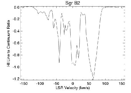
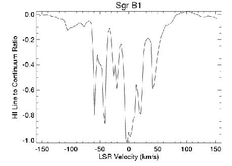
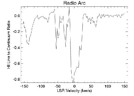
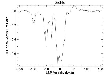
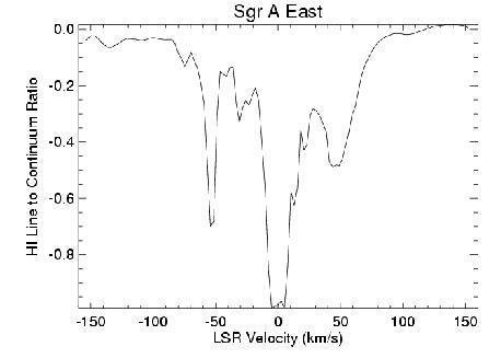
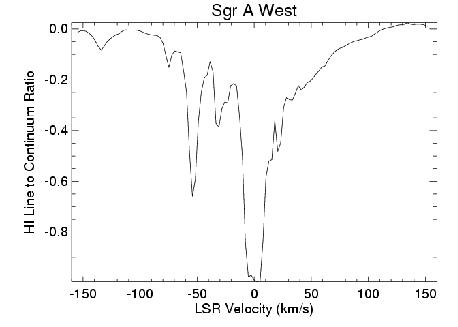
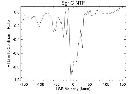
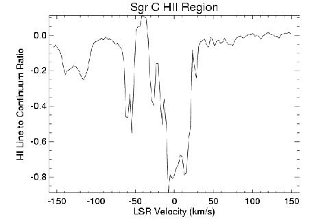
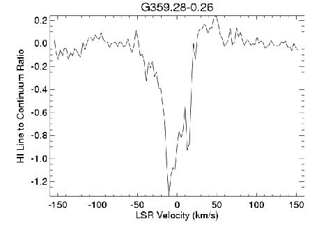
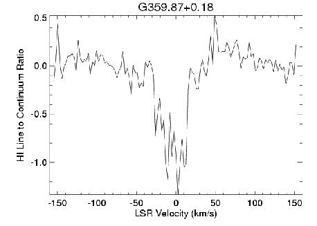
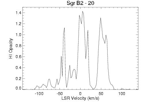
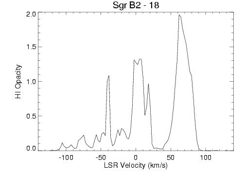
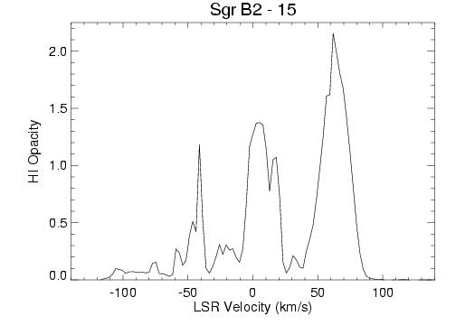
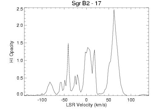
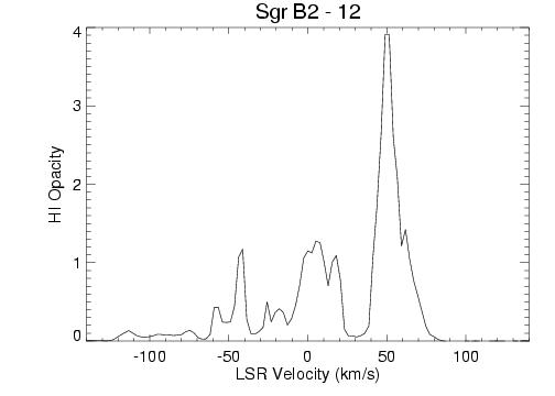
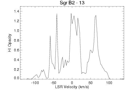
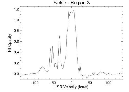
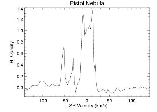
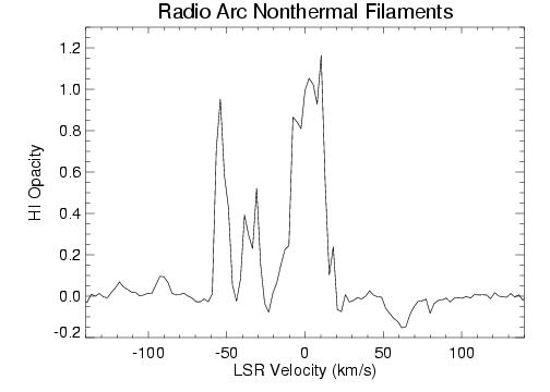
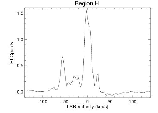
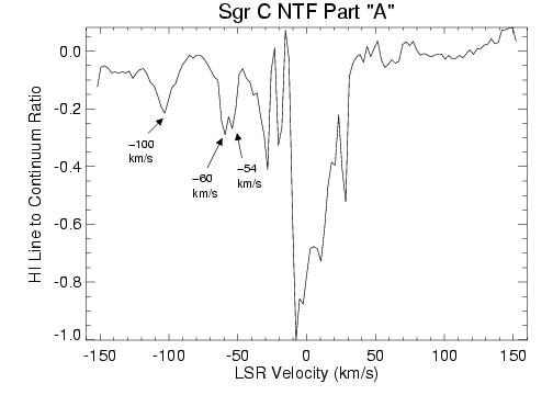
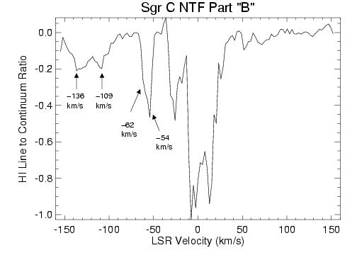
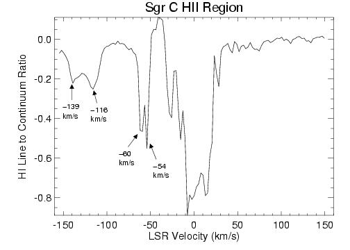
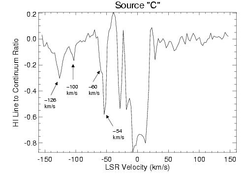
Figures 4-9 show a representative sample of 10 HI absorption profiles toward some of the well-known sources in the GC region: Sgr B1 and B2, Sgr A East and West, the Arched Filaments, Sickle and Radio Arc, the Sgr C nonthermal filament (NTF) and HII region, and two point-like sources in the field: G359.87+0.18 and G359.28-0.26. In all figures, there is deep HI absorption near 0 km s-1 from many components of atomic gas along the line of sight to the GC. Components of large HI absorption (line-to-continuum ratios equal to or greater than 0.4) are apparent in all but the two point-like sources (e.g, Figure 9) around velocities of 50 km s-1 and 20 km s-1. These components are likely to be associated with the non-circular velocities of gas near the GC region. In addition, most of the profiles show absorption at positive velocities. In Sgr B2 and B1, the strong absorption of the dense molecular cloud at 50-60 km s-1 is apparent. Toward the Radio Arc region (i.e., Sickle, Arched Filaments, Radio Arc nonthermal filaments) there is little absorption at positive velocities, and most of the absorption appears at negative velocities. Both profiles for Sgr A West and East show HI absorption at positive velocities; Sgr A West has a broad wing between 20 and 100 km s-1 which is discussed in 3.7, and atomic gas associated with the dense molecular streamers at v=20 and 50 km s-1 near Sgr A East are apparent in Figure 7 (top) (e.g, McGary et al. 2001; Coil et al. 1999). Figure 8 shows the HI absorption toward parts of the Sgr C complex: atomic gas associated with various molecular features near 100 and 60 km s-1 are evident. Finally, the profiles in Figure 9 show the HI absorption toward two point sources in the field. A more detailed discussion of the HI and its relationship to the other components of the interstellar medium in the GC for the main complexes (Sgr B, Radio Arc, and Sgr C) follows below in Sections 3.4, 3.5 and 3.6.
3.3 Large-Scale Negative Velocity HI Absorption
As mentioned above, prominent HI absorption occurs toward most bright continuum sources in this field at a number of negative velocities. Table 6 summarizes the negative velocity components and lists which continuum sources toward which the negative velocities are detected. A listing of four different clouds (A-D) is given in this table as well as the average velocity and rms noise, the FWHM and rms noise, and the average optical depth and rms noise of each component. The atomic gas associated with the 3 kpc-arm is present in Component A. Only 8 of the 40 continuum sources do not have absorption in the range of 54 to 60 km s-1 (i.e., Component A): sources 1, 2, 10, 11, 19, 27, 31, 40. In addition, Figures 10 and 11 show the distribution of HI opacity at 25 km s-1 (Component C) and 54 km s-1 (Component A), respectively, across the entire field of our HI study. The greyscale shows HI opacity and is overlaid on contours of molecular gas (CO (1-0) from Oka et al. (1998)) that define the orientation of the Galactic plane. The negative velocity components C and D (at velocities of 41 to 20 km s-1) are likely to be located within the central few hundred parsecs of the Galaxy where the gas motions are “forbidden” and may result from an inflow toward the GC region from the barred-potential distribution (e.g., Binney et al. 1991). This pattern is in agreement with the conclusion about the negative velocity molecular clouds that were detected toward the GC in the H2CO study of Mehringer et al. (1995).
3.4 HI Absorption toward the Sgr B Complex
Sgr B2 is one of the most massive star forming regions in the Galaxy. In addition to an extensive, dense molecular cloud ( 5 106 M☉), a large number of compact and ultra-compact HII regions and masers indicate that this region is young with many embedded sources. Higher resolution radio observations of Sgr B2 North (Sgr B2 (N))and Sgr B2 Main (Sgr B2 (M)) reveal 50 compact sources at sub-arcsecond level (Gaume et al. 1995; DePree et al. 1995, 1996). On the other hand, the radio emission arising from the Sgr B1 complex indicates that this region is a more highly evolved star-forming region than Sgr B2 with numerous filamentary and shell-like ionized structures (Mehringer et al. 1992).
The ionized and molecular gas in both regions have been studied at high spatial resolutions (e.g., Mehringer et al. 1993, Mehringer et al. 1992, Mehringer et al. 1995). The ionized gas in Sgr B2 has velocities between 50-70 km s-1 and the ionized gas in Sgr B1 has velocities between 30-50 km s-1. The Sgr B1 and B2 complexes are thought to be physically related and the velocity distribution across both of the molecular clouds supports this hypothesis. Absorption of H2CO (formaldehyde) gas toward Sgr B1 reveals that the molecular gas has a more extended and shell-like distribution than in Sgr B2 (Mehringer et al. 1995). In Sgr B2, the H2CO opacities are very high (e.g., 1 in many places and 5) and are often correlated in velocity with the radio recombination line data of Mehringer et al. (1993), suggesting that there may be compact HII regions embedded in this cloud (Mehringer et al. 1995).
G0.6-0.0 lies in projection between the prominent Sgr B2 and Sgr B1 complexes. The recombination line study of Mehringer et al. (1992) indicates that both kinematically and morphologically G0.6-0.0 is physically related to the Sgr B1 and Sgr B2 complexes. Figure 12 shows a 1.4 GHz continuum image of the Sgr B region from this study. Small regions for which HI absorption spectra were produced are labeled according to the nomenclature of Mehringer et al. (1993) for Sgr B2 and Mehringer et al. (1992) for Sgr B1 and G0.06-0.0. Table 7 lists fits to various interstellar components (HI, HII and H2CO) for each of these regions.
3.4.1 Sgr B2
The HI absorption is very strong across Sgr B2 at velocities of 5080 km s-1. Figure 13 shows the distribution of HI opacity for the Sgr B2 N and M components in greyscale (HI shown for values of 02) and contours representing the continuum emission. This plot was produced by making a cube of the distribtion of HI opacity for each pixel. The HI line absorption is very strongly saturated (i.e., 3-4) in these regions. Figure 14 shows the central velocity distribution of HI integrated over small regions (defined by the box size in this figure) in the Sgr B2 complex. Figures 15-18 show profiles of HI opacity for six regions in the Sgr B2 complex and columns 24 of Table 7 list the central line velocity (vHI), opacity (HI) and V (FWHM line width) fits for these profiles. Columns 5 and 7 give the central velocity of the H2CO absorption and ionized gas (HII), respectively, from Mehringer et al. (1995, 1993).
These HI absorption data reveal some patterns: toward Sgr B2 (N), the HI absorption occurs at higher velocities (6570 km s-1) than toward Sgr B2 (M), where the velocities are 60-65 km s-1. In addition, Sgr B2 (R) and Sgr B2 (S) have HI velocities between 5060 km s-1. The ionized gas from the H110 ratio recombination line study of Mehringer et al. (1993) shows that the ionized gas in the different components of Sgr B2 is very well-matched to the atomic gas. In fact, Table 7 shows that for the sources in Sgr B2, there is very close agreement between the velocities of HI, H2CO and HII gas in regions 18, 20, 15 and 17.
The current paradigm for the star formation occuring in the Sgr B2 complex is that molecular cloud collisions have likely triggered star formation throughout the region (Mehringer et al. 1993, 1995; Hasegawa et al. 1994, 2008). The well-known Sgr B2 molecular cloud has a velocity of 65 km s-1; however, the range of observed velocities is approximately 35-95 km s-1 (Hasegawa et al. 1994). H2CO absorption has revealed that there is a higher velocity cloud (v 80 km s-1) present that is thought to have been the trigger for star formation in this region. Interestingly, ionized gas is found in the vicinity of this molecular cloud at velocities that are intermediate between the two clouds (H110 velocities 70 km s-1 compared with 65 km s-1 and 80 km s-1 of the molecular gas; Mehringer et al. 1993). Variations in the opacity and kinematics of H2CO absorption and radio recombination lines over the Sgr B2 source indicate that sites of active star formation (HII regions) are embedded within the cloud at different line-of-sight distances.
The presence of HI and H2CO absorption at higher velocities toward Sgr B2 (N) may indicate that this source may be located deeper in the cloud than regions (such as R, Main) where there is no absorption at higher velocities. This pattern was first suggested by Mehringer et al. (1995). Toward Sgr B2 (R) there is HI absorption at relatively low velocities ( 55 km s-1). The absence of HI absorption at higher velocities from the molecular cloud on the backside of the Sgr B2 molecular cloud indicates that this source is likely to be on the nearest side of the complex. The cartoon in Figure 20 shows a sketch of a proposed line-of-sight arrangement of the atomic, ionized and molecular components in Sgr B2.
For the positions where both the HI absorption and H2CO absorption lines have good signal-to-noise, it is possible to make an estimate of the ratio of the number density of HI (NHI) to the number density of molecular hydrogen (N). Mehringer et al. (1995) provide the ratio of the column density of H2CO molecules to the excitation temperature (NL/Tex), which depends on the optical depth of the H2CO emission and the line width. The excitation temperature for H2CO is assumed to be 1-2 K (Mehringer et al. 1995). The column density of H2 can then be inferred by the ratio N/N = 2 10-9. For the strong lines in Sgr B2 complex, the values for column density of H2 are N=730 1022 cm-2. To derive the ratio of NHI to N, we need a measure of NHI, obtained by using the standard formula NHI = 1.92 1018 Tex V. Here, Tex for HI is not well known for the GC environment; we have assumed T=60 K. Values for NHI in Sgr B2 therefore range from 26 1021 cm-2, producing ratios of NHI to N of 0.02-0.05. These values are consistent with similar values obtained by Lasenby et al. (1989) in their HI absorption study of the central 50 pc. Table 7 lists the NHI to N ratio in column 6. In addition, the close correlation in distribution and central velocity of the HI absorption and the ionized gas also suggests that atomic gas resides in photo-dissociation regions related to the HII regions in the GC similar to the scenario in both W3 and Orion B (e.g., van der Werf & Goss 1990; van der Werf et al. 1993).
3.4.2 Sgr B1 and G0.6-0.0
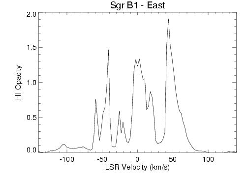
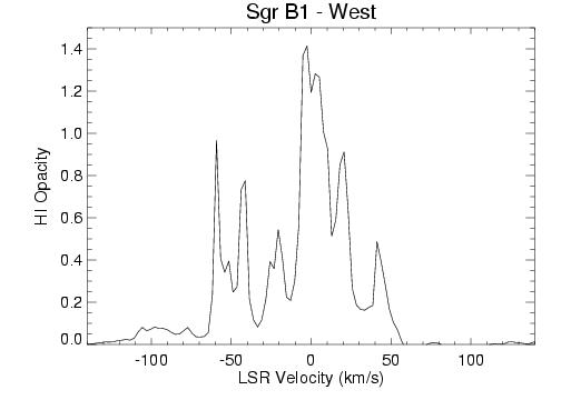
Sgr B1 can be divided into an Eastern component (Sgr B1-East) and Western component (SgrB1-West). In previous studies of both ionized and molecular gas, these regions are also known to be kinematically distinct (Mehringer et al. 1992, 1995). The integrated HI opacity profiles for these regions are shown in Figure 18, and fits to these profiles are listed in Table 7. The main positive-velocity HI feature in Sgr B1-East is centered at 47 km s-1, with 2. The molecular gas absorption has a similar velocity (+50 km s-1; Mehringer et al. 1995). Using the H2CO absorption feature near +50 km s-1, we calculate the ratio of NHI to N (as above) and obtain a value of 0.1, about 2-3 times as large as the values in Sgr B2 (0.02-0.05). The velocities of the ionized gas in Sgr B1-East are +30 km s-1, and at +60 km s-1, not as well-correlated to the velocities of the atomic and molecular material.
The HI absorption profile toward Sgr B1-West shows two components at +20 km s-1 and +40 km s-1, with values of of 0.5. The ionized gas toward this region is in the range of +40 to +45 km s-1, and the H2CO absorption occurs over the range of +30 to +40 km s-1. The atomic gas is therefore likely to be associated with the ionized and molecular gas in the +40 km s-1 cloud. Due to the low signal to noise in both the HI and H2CO profiles, the NHI to N ratio for this region is quite uncertain. Mehringer et al. (1995) present a scenario for the Sgr B1-East and Sgr B1-West HII regions in which Sgr B1-West HII region is on the nearside of the Sgr B1 molecular cloud (with v=+40-50 km s-1) and the Sgr B1-East HII region lies on the backside of the molecular cloud. The lack of H2CO absorption near +50 km s-1 toward Sgr B1-West indicates to Mehringer et al. (1995) that this feature is located on the nearside of the cloud. The HI profiles presented here appear to follow this general pattern, with no HI absorption at +50 km s-1 toward Sgr B1-West, and the atomic gas more closely associated in velocity to the ionized component.
Figure 19 shows the HI opacity toward the source G0.6-0.0. The prominent HI absorption occurs at 52 km s-1. The velocities of the atomic, molecular and ionized gas in this region agree well at approximately +51-55 km s-1. These values lie between the range for Sgr B1 (+40 to +50 km s-1) and Sgr B2 (+60 to +70 km s-1), further indicating that G0.6-0.0 may be a kinematically-intermediate region between Sgr B1 and Sgr B2. The NHI to N ratio for G0.6-0.0 is 0.2. This order of magnitude difference from the ratio measured in Sgr B2 may be due to the lower column of molecular gas in this region. The HI column densities for both G0.6-0.0 and Sgr B1 regions are similar (but are typical of the lower end of the range) to those in Sgr B2. In general, the HI optical depths are lower toward the Sgr B1 components (0.5-1.5) than in Sgr B2 ( 2 or more). These lower values are also consistent with the idea that the material related to star formation (i.e. molecular gas and the associated ionized layers) is more dispersed in Sgr B1 and G0.6-0.0 and that these sources are more evolved than Sgr B2.
3.5 HI Absorption toward the GC Radio Arc
The GC “Radio Arc” region consists of a number of thermal and non-thermal features. Figure 21 shows the 1.4 GHz continuum image from these data. The major features of this region are labeled: (1) the linear, non-thermal filaments (also known as NTFs) which extend for 16′ (40 pc), first discovered by Yusef-Zadeh et al. (1984), (2) the thermal Arched Filaments HII regions which have been studied in detail by Lang et al. (2001, 2002) and are assumed to be ionized by the massive Arches cluster (Figer et al. 2002), (3) the thermal Sickle HII region and Pistol Nebula, known to be associated with the Quintuplet cluster (Figer et al. 1999), and (4) the “H”-regions, a set of 5 compact HII regions that are located in projection between the SgrA complex and the Arched Filaments (Yusef-Zadeh & Morris 1987; Zhao et al. 1993). There are two well-known molecular clouds in the vicinity of the Radio Arc that are thought to be physically associated with the radio continuum sources: the “-30 km s-1 cloud” and the “+25 km s-1 cloud” (Serabyn & Guesten 1987; Serabyn & Guesten 1991). Both clouds have forbidden velocities, likely due to their highly non-circular orbits around the GC. Therefore, we have examined the HI absorption in detail near these velocities. Figures 22 and 23 show contours of 1.4 GHz continuum emission overlaid with greyscale representing the HI opacity for velocities around 30 km s-1 (Figure 22) and +25 km s-1 (Figure 23) toward the Radio Arc region.
3.5.1 Arched Filaments HII Complex
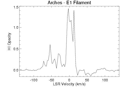
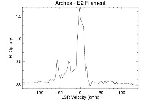
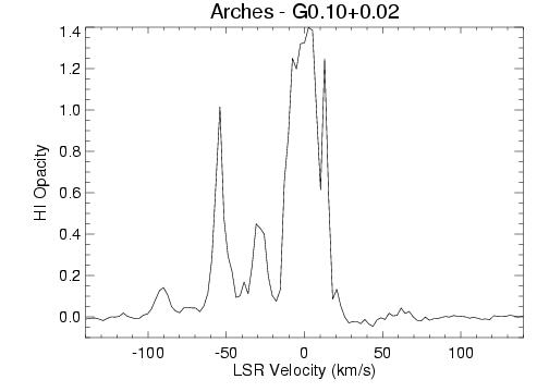
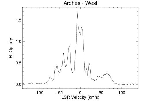
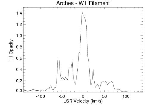
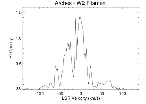
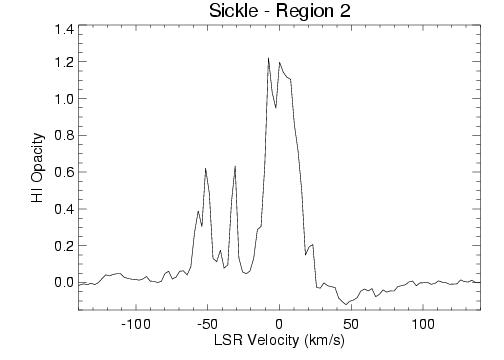
Figures 24-26 show continuum-weighted, integrated profiles of HI opacity for small regions (1-2′) in the Arched Filaments HII complex. These regions are labeled according to their location in the Arched Filaments, which is shown in Figure 21: the Eastern portions (Arches-E1, Arches-E2) and Western portions (Arches-West, Arches-W1 and Arches-W2). Table 8 lists the fits to the HI components that have the highest signal-to-noise, as well as the central velocities of the ionized and molecular gas from previously-published studies (e.g., Serabyn & Guesten 1987; Lang et al. 2001).
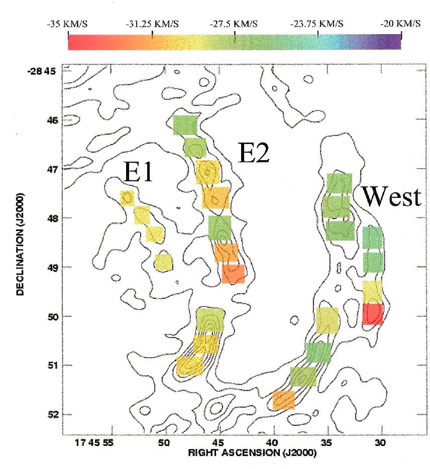
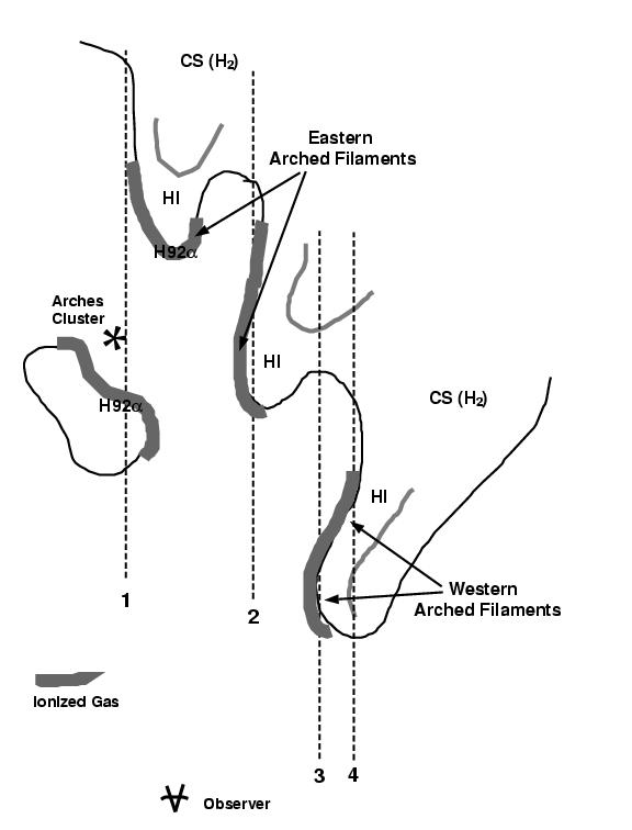
The velocities of the ionized, atomic and molecular gas components are in a narrow range, primarily between 28 km s-1 and 55 km s-1, with much of all three components near 30 to 40 km s-1. To further illustrate the velocity structure of the HI absorption, Figure 27 shows the central velocity for the HI determined from opacity profiles made over even smaller regions (indicated by the squares in Figure 27). Here, it is also clear that much of the HI component lies at velocities of 25 to 35 km s-1. Figure 28 shows a cartoon from the paper by Lang et al. (2002), where the authors suggest an arrangement of the ionized, molecular and atomic gas and how this interstellar material may be arranged around the ionizing cluster. The velocities of the HI absorption from this study and as compared with the ionized and molecular gas from previous work appear to be consistent with this scenario.
3.5.2 Sickle HII Region, Pistol Nebula and Radio Arc Nonthermal Filaments
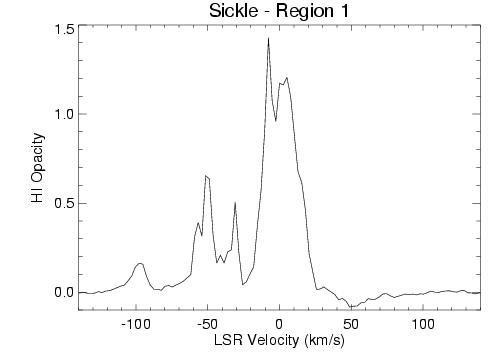
Figures 29-31 show continuum-weighted, integrated profiles of HI opacity for small regions (30″ 30″) in the Sickle HII region and Pistol Nebula. Table 8 lists the fits to the HI components where the signal-to-noise is the highest. In addition, central velocities are listed for the ionized and molecular gas in this vicinity (due to the “+25 km s-1 cloud”) from previously- published studies (e.g., Serabyn & Guesten 1991; Lang et al. 1997). Unlike in the Arched Filaments complex, the correlation between atomic, ionized and molecular gas is not as strong. In fact, both the ionized and molecular gas are dominated by positive velocities (e.g., near +25 km s-1) while the atomic gas is concentrated at negative velocities (e.g., 30-50 km s-1). One possible explanation for the 50 km s-1 difference in the velocities of the interstellar components is if the atomic gas lies in a shell-like distribution in front of the Radio Arc and is expanding away from this region. Such an arrangement could be related to the episodes of massive star formation that are ongoing in the GC Radio Arc (Wang, Dong & Lang 2006) and is in agreement with a similar suggestion by Lasenby et al. (1989). In general, these observations compare very favorably to the earlier HI absorption study of Lasenby et al. (1989), which covered the Radio Arc region in detail. Here, the velocity resolution of the HI data is improved, and the corresponding ionized and molecular line observations have higher spatial resolutions. However, the conclusions are similar: much of the atomic gas in this region appears to lie on the near side of the continuum arc and filaments in the Radio Arc. Figure 31 shows a continuum-weighted, integrated profile of HI opacity for a region of the NTFs in the Radio Arc that lie east of the Sickle and Pistol. The main HI absorption occurs near -50 km s-1 and 30 km s-1, indicating that there is atomic material on the near side of the NTFs at these “forbidden” velocities. This atomic material is likely to be physically related to several clouds in the region at similar velocities (i.e, the 30 km s-1 cloud).
3.5.3 ’H’- regions: HII regions
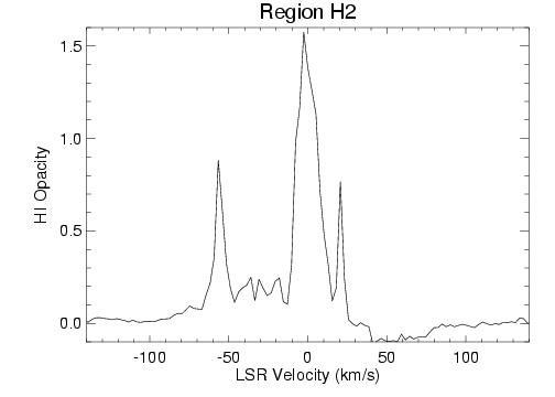
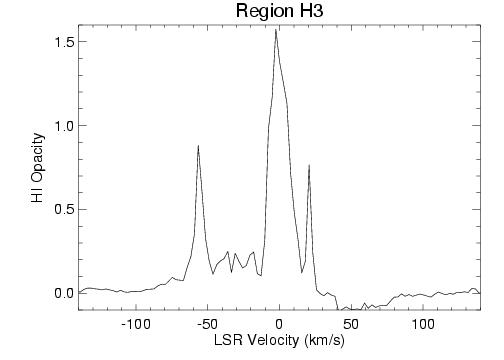
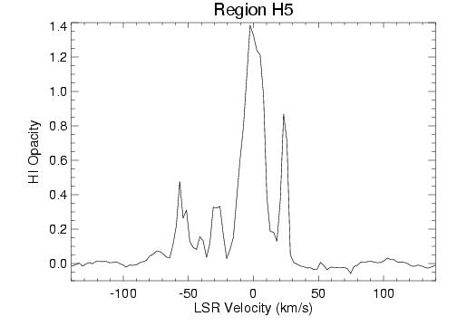
Figures 32 and 33 show continuum-weighted, integrated profiles of the HI opacicty toward the compact HII regions known as H1, H2, H3 and H5. Table 8 lists the fits to the HI components where the signal-to-noise is the highest. The table also lists the central velocities of the ionized and molecular gas from previously-published studies (i.e., Zhao et al. 1993; Serabyn & Guesten 1987). Especially noticable is the close correlation between the ionized, molecular and atomic components in these compact HII regions. The similarity in velocities of the ionized and molecular gas in the HII regions suggest that they are part of the larger molecular gas reservoir that is associated with the Arched Filaments complex.
3.6 HI Absorption toward the Sgr C Complex
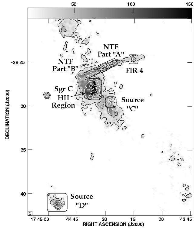
The Sgr C complex (G359.45-0.05) is located 30′ (or 75 pc) in projection to the South of the Sgr A complex, along the Galactic plane. Figure 34 shows the 1.4 GHz continuum image of the main components of the Sgr C complex: the SgrC HII region, the NTF, and HII regions known as FIR 4, Source C and D (Liszt & Spiker (1995), Roy (2003), and Odenwald & Fazio (1984)). The NTF has been labeled “Part A” and “Part B” after Roy (2003). There are similiarities between Sgr C and the Radio Arc: the Sgr C HII region may contain more than 250 solar masses of ionized gas with massive stars present, including some late-type O stars. This HII region is associated with a molecular cloud which has the same velocity (65 km s-1). The molecular cloud associated with Sgr C appears to be organized in a shell-like distribution surrounding the HII region; the massive stars are thought to have blown a cavity in the distribution of gas (Lizst & Spiker 1995). Finally, the Sgr C NTF is also thought to be physically related to this star formation region.
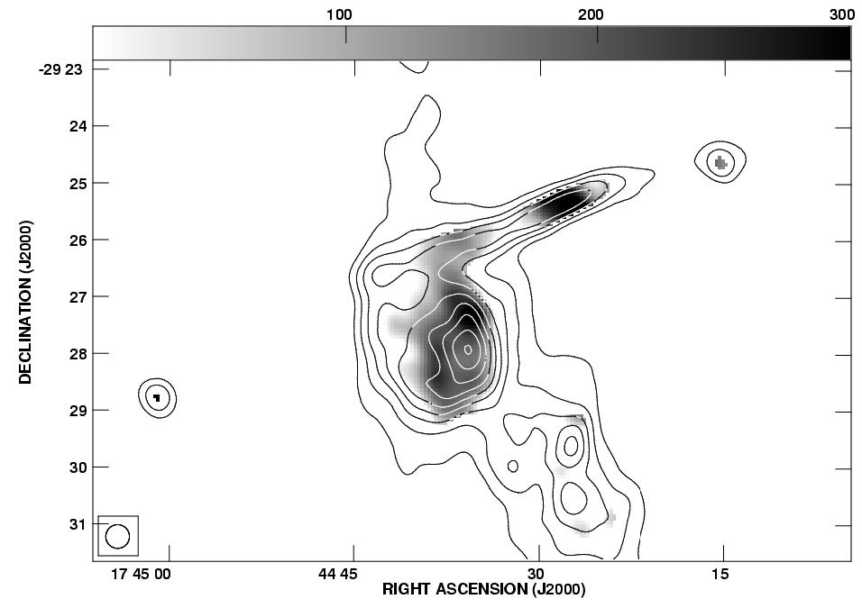
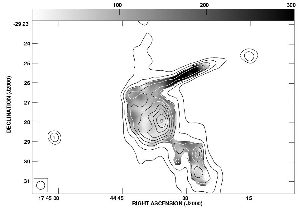
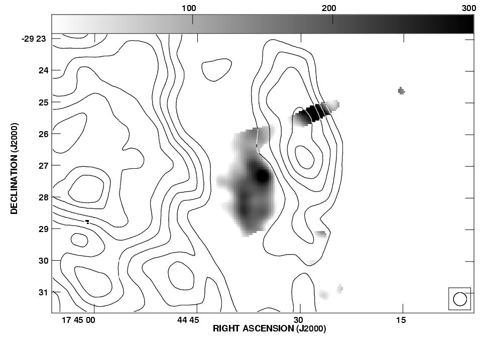
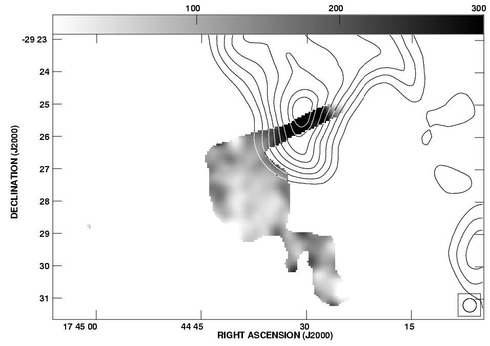
Figures 35-37 show the corresponding integrated HI absorption profiles for each of these regions: Part A and B of the Sgr C NTF, the SgrC HII region, FIR4, and Sources C and D. Most of the profiles have a complicated velocity structure with absorption at many velocities. As mentioned above, there are molecular clouds in this region with velocities of 65 km s-1 and 100 km s-1, noted by Liszt & Spiker (1995) and Oka et al. (2001). Figure 38 shows contours of 1.4 GHz radio continuum emission overlaid on greyscale representing the HI optical depth at velocities of 65 km s-1 and 100 km s-1. Figure 39 shows the same HI optical depth as in Figure 38 overlaid on contours of CO (J=1-0) emission from the survey of Oka et al. (1998) at velocities of 65 km s-1 and 100 km s-1.
3.6.1 Sgr C NTF
Figure 35 shows the HI absorption profile toward Part A and Part B of the Sgr C NTF. These profiles are similar with HI absorption near 60-65 km s-1 toward both regions of the NTF, but clearly stronger toward Part B of the NTF. This difference in the HI absorption by the 65 km s-1 cloud across the Sgr C NTF is striking and may indicate that the atomic gas in the direction of Part A is embedded in or located on the backside of the 65 km s-1 molecular cloud. In addition, there is HI absorption near 100 km s-1 in both profiles. In Part B, the HI absorption occurs at 136 and 109 km s-1; both components may be associated with the 100 km s-1 molecular cloud if there is a velocity gradient.
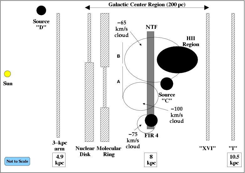
Figures 35 and 38 (right) illustrate that the HI absorption by the 100 km s-1 cloud is stronger toward Part A of the NTF (HI=0.15) than toward Part B of the NTF (HI=0.45). In addition, Figure 39 (right) shows that the distribution of molecular gas traced in the CO emission near 100 km s-1 peaks near Part A of the NTF and is nearly absent near Part B of the Sgr C NTF. This correlation of the stronger HI absorption at 100 km s-1 with the peak of molecular gas suggests that the atomic gas is physically associated with the molecular cloud at this location and lies behind the NTF. The change in HI absorption across the NTF (from HI=0.45 to 0.15 from Part A to Part B) indicates that the atomic and molecular material may be located partially in front of the NTF as the continuum brightness of the NTF does not vary substantially across these regions. The NTF may be embedded in or located on the backside of the 100 km s-1 molecular cloud. Figure 40 illustrates the a possible arrangement of interstellar sources in this region (and in particular, the arrangement of the molecular cloud and NTF).
3.6.2 Sgr C HII Region
Figure 36 (left) shows that the HI absorption toward the Sgr C HII region is strongest near 60 km s-1, also the velocity range of the known CO cloud associated with the Sgr C HII region (Liszt & Spiker 1995). The radio recombination line spectrum of the HII region is centered on 65.5 km s-1. Therefore, it is likely that the HI at this velocity is physically associated with this complex. Further, we can obtain some details about location relative to the molecular and ionized components by comparing the distribution of each component. Figure 39 (left) shows that the Sgr C HII Region appears to be located in a cavity of the 65 km s-1 molecular material; there is a striking, exact anti-correlation between the atomic/HII and molecular components. The absorption against the Sgr C HII region indicates that there is atomic material on the near side of the HII region, probably mixed in with the ionized gas. The molecular material may presumably have been ionized and blown out of this cavity. It is less clear that there is 100 km s-1 HI absorption toward the Sgr C HII region; in fact, the absorption near 100 km s-1 shifts to 120 km s-1 near the Sgr C HII region and may not be part of the same cloud (in agreement with Liszt & Spiker (1995)) and the 100 km s-1molecular material is only observed towards Part A of the Sgr C NTF in Figure 37 (right).
The Sgr C NTF and the Sgr C HII Region both appear to be associated with the 65 km s-1molecular cloud in the Sgr C region, which suggests that the NTF and HII region themselves are physically related. This possible association between the HII region and NTF is particularly relevant to the mechanism for accelerating particles along the NTFs, an open issue in understanding the nature of these unusual non-thermal filaments. Serabyn & Morris (1994) have previously suggested that the relativistic particles present along the NTFs originate in the ionized edges of molecular clouds, based on their finding of molecular clumps coinciding with NTFs in the Radio Arc. Therefore, the scenario in Sgr C may be consistent with this picture.
3.6.3 HII Regions Surrounding Sgr C and Line-of-Sight Arrangement
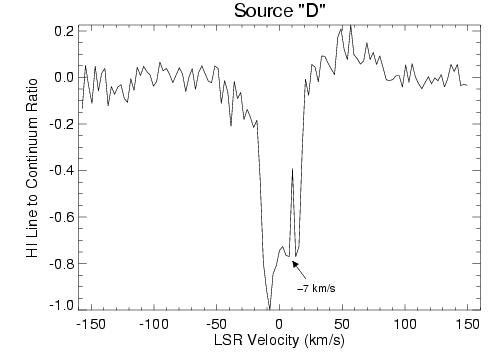
Figure 36 (right) and Figure 37 show the HI absorption toward three HII regions adjacent to Sgr C: FIR 4, Source C and D. Due to the low surface brightness of FIR 4 in the 1.4 GHz continuum, the HI absorption data has low signal to noise (Figure 36 (right)). The prominent features in Figure 36 (right) are HI absorption near 80 km s-1 ,54km s-1, and 135 km s-1. The lack of absorption due to either the 100 km s-1 molecular cloud or the 65 km s-1 molecular could indicate that FIR 4 could be located in front of these clouds but beyond the 3-kpc arm at 5 kpc, since the 54 km s-1 absorption component is present. Source C has an absorption spectrum which appears very similar to the other sources in the Sgr C complex, with absorption near 60 km s-1, 100 km s-1 and 126 km s-1. By contrast, Source D only has HI absorption features in the range of 30 to 30 km s-1, suggesting that it may be nearer to the Sun along the line of sight.
Using the comparison of atomic absorption and molecular and ionized gas velocities, we can make a schematic of the line-of-sight arrangement of the sources and ISM surrounding Sgr C. A possible arrangement from the results presented in this paper is shown in Figure 40 (as viewed from above, looking down on the region, with the observer to the left in the drawing). We make the following assumptions: Source D is a foreground source located somewhere between the Sun and the 3 kpc arm, not associated with the rest of the Sgr C region. The atomic gas associated with the 65 km s-1 molecular cloud is likely to be located in front of the Sgr C HII Region, Source C and likely to be physically associated with the Sgr C NTF. The atomic gas associated with the 100 km s-1 molecular cloud is also likely to be located on the near side of the Sgr C NTF (and possibly physically related) and of Source C. The results presented here (including the line-of-sight arrangement of components associated with Sgr C) agree very well with those derived in Roy (2003) using the GMRT. The spatial and velocity resolutions are very comparable; our survey differs in that it covers a large region whereas the Roy (2003) observations were targeted at several NTFs.
3.7 HI Absorption toward Sgr A: High Spatial Resolution Data
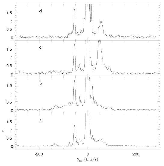
Complementary HI observations of the Sgr A field were carried out by Dwarakanath, Goss, Zhao and Lang (2004) using the VLA in the A, B, C and D arrays in January and October of 2002. The purpose of these observations was to elucidate the nature of the wide line (VFWHM about 100 km s-1) toward Sgr A. These complementary observations have a much larger velocity coverage of 600 km s-1 and a velocity resolution of 1.3 km s-1. The wide velocity range was required to cover the large number of velocity components at the GC, while the high velocity resolution was required to identify and remove the narrow HI absorption lines. Figure 41 shows the HI spectra obtained with an angular resolution of 8″ at four positions in SgrA West: The spectrum ’a’ is toward SgrA* while ’b’ is displaced by 35″ to the SW. Positions ’c’ and ’d’ are located 2′ E and NE of SgrA* and within the SNR SgrA East. A number of narrow lines (10 km s-1) are obvious. In the ’b’ direction a broad shoulder is observed, implying a wide component with a VFWHM of 120 km s-1. At positions ’c’ and ’d’, the wide line is not detected. The wide line is interpreted to originate in various HI components of the circumnuclear disk (’CND’) with a radius of 1.3′ centered on SgrA*. These components have central velocities of 100 km s-1 to the N of Sgr A* and 100 km s-1to the S. The observed wide line in the direction of SgrA does not represent a component of low opacity, turblent shocked HI clouds; this feature is the result of the superposition of various components of the CND surrounding SgrA* (e.g., see Dwarakanath et al. 2004 for more details).
3.8 Constraining Line-of-Sight Distances to GC Sources
The majority of continuum sources in this study have absorption due to the “3-kpc arm” (at a velocity of 54 km s-1 and at a distance of 5 kpc). Table 5 lists the presence of this absorption feature in each spectrum. The presence of this feature suggests that these sources must lie beyond 5 kpc. Additionally, many of these sources are associated with forbidden-velocity molecular clouds that are believed to lie at the GC. The HI spectra, therefore, of the majority of the sources in Table 5 are consistent with the sources being at a GC distance of d=8 kpc. Only three sources (G0.32-0.19, G0.31-0.20, and G359.28-0.26) do not show absorption by the 3-kpc arm. The absence of this feature suggests that these sources may lie between the Sun and the 3-kpc arm and we consider these to be foreground sources. Finally, the extragalactic source G359.87+0.18 has been studied by Lazio et al. (1999) and our HI spectrum for this source is in agreement with these findings.
A website has been created to disseminate the images, profiles and data to the astronomical community (see http://astro.physics.uiowa.edu/clang/gchi).
References
- Bally et al. (1988) Bally, J., Stark, A. A., Wilson, R. W., & Henkel, C. 1988, ApJ, 324, 223
- Becker et al. (1994) Becker, R. H., White, R. L., Helfand, D. J., & Zoonematkermani, S. 1994, ApJS, 91, 347
- Binney et al. (1991) Binney, J., Gerhard, O. E., Stark, A. A., Bally, J., & Uchida, K. I. 1991, MNRAS, 252, 210
- Cohen & Davies (1976) Cohen, R. J. & Davies, R. D. 1976, MNRAS, 175, 1
- Cohen & Davies (1979) Cohen, R. J. & Davies, R. D. 1979, MNRAS, 186, 453
- Coil & Ho (1999) Coil, A. L., & Ho, P. T. P. 1999, ApJ, 513, 752
- Dickey & Lockman (1990) Dickey, J. M., & Lockman, F. J. 1990, ARA&A, 28, 215
- Dwarakanath et al. (2004) Dwarakanath, K. S., Goss, W. M., Zhao, J. H., & Lang, C. C. 2004, Journal of Astrophysics and Astronomy, 25, 129
- Egan et al. (1998) Egan, M. P., Shipman, R. F., Price, S. D., Carey, S. J., Clark, F. O., & Cohen, M. 1998, ApJ, 494, L199
- Gaume & Claussen (1990) Gaume, R. A. & Claussen, M. J. 1990, ApJ, 351, 538
- Kulkarni & Heiles (1988) Kulkarni, S. R. & Heiles, C. 1988, In G. L. Verschuur & K. I. Kellermann (eds.), Galactic and Extragalactic Radio Astronomy. New York: Springer-Verlag, p. 101-103, 127-128
- Lang et al. (1997) Lang, C. C., Goss, W. M., & Wood, D. O. S. 1997, ApJ, 474, 275
- Lang et al. (2001) Lang, C. C., Goss, W. M., & Morris, M. 2001, AJ, 121, 2681
- Lang et al. (2002) Lang, C. C., Goss, W. M., & Morris, M. 2002, AJ, 124, 2677
- LaRosa et al. (2000) LaRosa, T. N., Kassim, N. E., Lazio, T. J. W., & Hyman, S. D. 2000, ApJ, 119, 207
- Lasenby et al. (1989) Lasenby, J., Lasenby, A. N., & Yusef-Zadeh, F. 1989, ApJ, 343, 177
- Lazio et al. (1999) Lazio, T. J. W., Anantharamaiah, K. R., Goss, W. M., Kassim, N. E., & Cordes, J. M. 1999, ApJ, 515, 196
- Lis & Carlstrom (1994) Lis, D. C. & Carlstrom, J. E. 1994, ApJ, 424, 189
- Liszt et al. (1983) Liszt, H. S., van der Hulst, J. M., Burton, W. B., & Ondrechen, M. P. 1983, A&A, 126, 341
- Liszt et al. (1985) Liszt, H. S., Burton, W. B., & van der Hulst, J. M. 1985, A&A, 142, 245
- Liszt & Spiker (1995) Liszt, H. S. & Spiker, R. W. 1995, ApJS, 98, 259
- McGary et al. (2001) McGary, R. S., Coil, A. L., & Ho, P. T. P. 2001, ApJ, 559, 326
- Mehringer et al. (1992) Mehringer, D. M., Yusef-Zadeh, F., Palmer, P., & Goss, W. M. 1992, ApJ, 401, 168
- Mehringer et al. (1993) Mehringer, D. M., Palmer, P., Goss, W. M., & Yusef-Zadeh, F. 1993, ApJ, 412, 684
- Mehringer et al. (1995) Mehringer, D. M., Palmer, P., & Goss, W. M. 1995, ApJS, 97, 497
- Odenwald & Fazio (1984) Odenwald, S. F. & Fazio, G. G. 1984, ApJ, 283, 601
- Oka et al. (1998) Oka, T., Hasegawa, T., Sato, F., Tsuboi, M, & Miyazaki, A. 1998, ApJS, 118, 455
- Oka et al. (2001) Oka, T., Hasegawa, T., Sato, F., Tsuboi, M, Miyazaki, A., & Sugimoto, M. 2001, ApJ, 562, 348
- Radhakrishnan & Sarma (1980) Radhakrishnan, V., & Sarma, N. V. G. 1980, A&A, 85, 249
- Reid (1993) Reid, M. J. 1993, ARA&A, 31, 345
- Roy (2003) Roy, S. 2003 A&A, 403, 917
- Sakano et al. (2004) Sakano, M., Warwick, R. S., & Decourchelle, A. 2004, ASR, 33, 403
- Schwarz et al. (1977) Schwarz, U. J., Shaver, P. A., & Ekers, R. D. 1977, A&A, 54, 863
- Schwarz et al. (1982) Schwarz, U. J., Ekers, R. D., & Goss, W. M. 1982, A&A, 110, 100
- Serabyn & Morris (1994) Serabyn, E. & Morris, M. 1994, ApJ, 424, L91
- Serabyn & Guesten (1991) Serabyn, E., & Guesten, R. 1991, A&A, 242, 376
- Serabyn & Guesten (1987) Serabyn, E., & Guesten, R. 1987, A&A, 184, 133
- Sofue (2006) Sofue, Y. 2006 PASJ, 58, 335
- Tsuboi et al. (1999) Tsuboi, M., Handa, T., & Ukita, N. 1999, ApJS, 120, 1
- Uchida et al. (1992) Uchida, K., Morris, M., & Yusef-Zadeh, F. 1992, AJ, 104, 1533
- van der Werf et al. (1993) van der Werf, P. P., Goss, W. M., Heiles, C., Crutcher, R. M., & Troland, T. H. 1993, ApJ, 411, 247
- van der Werf & Goss (1990) van der Werf, P. P., & Goss, W. M. 1990, A&A, 238, 296
- Wang et al. (2002) Wang, Q. D., Gotthelf, E. V., & Lang, C. C. 2002, Nature, 415, 148
- Wang et al. (2006) Wang, Q. D., Dong, H., & Lang, C. 2006, MNRAS, 371, 38
- Yusef-Zadeh et al. (1984) Yusef-Zadeh, F., Morris, M., & Chance, D. 1984, Nature, 310, 557
- Yusef-Zadeh & Morris (1987) Yusef-Zadeh, F., & Morris, M. 1987, ApJ, 320, 545
- Yusef-Zadeh et al. (2004) Yusef-Zadeh, F., Hewitt, J. W., & Cotton, W. 2004, ApJS, 155, 421
- Yusef-Zadeh et al. (2007) Yusef-Zadeh, F., Muno, M., Wardle, M., & Lis, D. C. 2007, ApJ, 656, 847
- Zhao et al. (1993) Zhao, J.-H., Desai, K., Goss, W. M., & Yusef-Zadeh, F. 1993, ApJ, 418, 235
| Field | Date | Array | Phase Center | Integration Time | |
|---|---|---|---|---|---|
| (J2000) | (J2000) | (hours) | |||
| GCHI-1 | Sept 2001 | DnC | 17 47 00.3 | 28 32 06 | 1.6 |
| Jun 2001 | CnB | 4 | |||
| GCHI-2 | Sept 2001 | DnC | 17 46 24.5 | 28 44 55 | 1.6 |
| Jun 2001 | CnB | 4 | |||
| GCHI-3 | Sept 2001 | DnC | 17 45 48.9 | 28 57 44 | 1.6 |
| Jun 2001 | CnB | 4 | |||
| GCHI-4 | Sept 2001 | DnC | 17 45 13.1 | 29 10 32 | 1.6 |
| Jun 2001 | CnB | 4 | |||
| GCHI-5 | Sept 2001 | DnC | 17 44 37.2 | 29 23 20 | 1.6 |
| Jun 2001 | CnB | 4 | |||
| Parameter | HI Data |
|---|---|
| HI Rest Frequency | 1420.406 MHz |
| LSR Central Velocity | 0 km s-1 |
| Total Bandwidth | 1.5625 MHz (330 km s-1) |
| Number of Channels | 127 |
| Channel Separation | 12.2 kHz (2.5 km s-1) |
| Velocity Coverage | 330 km s-1 |
| Flux Density Calibrator | 3C286 |
| Bandpass Calibrator | NRAO 530 (1730-130) |
| Phase Calibrator | 1751-253 |
| Source | Source | RA | DEC | Geom. Size | ||
|---|---|---|---|---|---|---|
| Name | Type | (h m s) | (d ) | (mJy beam-1) | (mJy) | (arcsec) |
| G0.60-0.20 | Compact | 17 47 50.23 | -28 31 25.3 | 3110††Source is unresolved and we list peak intensity (mJy beam-1) | ||
| G0.59+0.05 | Extended | 17 46 49.90 | -28 24 10.9 | 559 | 45484 | 40 |
| G0.59-0.13 | Compact | 17 47 30.17 | -28 29 57.4 | 4310 | 8728 | 15 |
| G0.53+0.18 | Compact | 17 46 10.01 | -28 23 24.7 | 31510 | 50424 | 11 |
| G0.53+0.13 | Extended | 17 46 22.06 | -28 25 03.0 | 3610 | 10636 | 20 |
| G0.50+0.17 | Compact | 17 46 08.30 | -28 25 31.7 | 4610 | 13336 | 21 |
| G0.49+0.19 | Extended | 17 46 02.39 | -28 24 50.0 | 689 | 36859 | 31 |
| G0.48+0.07 | Extended | 17 46 28.21 | -28 29 15.6 | 8010††Source is unresolved and we list peak intensity (mJy beam-1) | ||
| G0.48-0.10 | Compact | 17 47 08.20 | -28 34 48.3 | 4610 | 6422 | 10 |
| G0.47-0.10 | Compact | 17 47 06.00 | -28 35 11.2 | 4410 | 8226 | 13 |
| G0.43-0.06 | Compact | 17 46 51.39 | -28 36 09.1 | 5310 | 7221 | 9 |
| G0.38+0.02 | Extended | 17 46 27.79 | -28 36 03.6 | 4229 | 154543 | 24 |
| G0.35-0.03 | Compact | 17 46 32.68 | -28 39 14.1 | 8910 | 178.328 | 15 |
| G0.33-0.01 | Extended | 17 46 27.65 | -28 39 25.0 | 1609 | 1618101 | 45 |
| G0.32-0.19 | Compact | 17 47 07.22 | -28 45 58.7 | 6810††Source is unresolved and we list peak intensity (mJy beam-1) | ||
| G0.31-0.20 | Extended | 17 47 09.76 | -28 46 23.2 | 3410 | 6426 | 13 |
| G0.21-0.00 | Compact | 17 46 07.40 | -28 45 27.9 | 18210 | 44732 | 18 |
| G0.17+0.15 | Extended | 17 45 26.13 | -28 42 43.9 | 6310 | 12427 | 15 |
| G359.87+0.18 | Compact | 17 44 37.08 | -28 57 06.5 | 10110††Source is unresolved and we list peak intensity (mJy beam-1) | ||
| G359.87-0.09 | Compact | 17 45 38.34 | -29 05 44.1 | 19110 | 44631 | 17 |
| G359.73-0.04 | Compact | 17 45 06.27 | -29 11 19.9 | 12210 | 63457 | 31 |
| G359.72-0.04 | Compact | 17 45 05.06 | -29 11 45.7 | 15110 | 72253 | 29 |
| G359.65-0.06 | Extended | 17 44 59.41 | -29 16 05.0 | 989 | 34642 | 24 |
| G359.65-0.08 | Extended | 17 45 05.03 | -29 16 45.2 | 1439 | 129592 | 43 |
| G359.47-0.17 | Extended | 17 45 00.88 | -29 28 47.6 | 729 | 38558 | 31 |
| G359.36+0.00 | Compact | 17 44 06.00 | -29 28 43.5 | 269 | 7235 | 20 |
| G359.31-0.06 | Compact | 17 44 10.44 | -29 33 25.7 | 299 | 12148 | 27 |
| G359.28-0.26 | Extended | 17 44 55.66 | -29 41 10.6 | 1289 | 88472 | 36 |
| Source | Source | RA | DEC | |||
|---|---|---|---|---|---|---|
| Name | Type | (h m s) | (d ) | (mJy) | (mJy) | (mJy) |
| G0.60-0.20 | Compact | 17 47 50.23 | -28 31 25.3 | 3110††Source is unresolved and we list peak intensity (mJy beam-1) | 113 | |
| G0.53+0.18 | Compact | 17 46 10.01 | -28 23 24.7 | 50424 | 236425 | 30330 |
| G0.48-0.10 | Compact | 17 47 08.20 | -28 34 48.3 | 6522 | 439 | |
| G0.47-0.10 | Compact | 17 47 06.00 | -28 35 11.2 | 89826 | 347 | |
| G0.43-0.06 | Compact | 17 46 51.39 | -28 36 09.1 | 7221 | 556 | |
| G0.38+0.02 | Extended | 17 46 27.79 | -28 36 03.6 | 154543 | 82080 | 1417425 |
| G0.35-0.03 | Compact | 17 46 32.68 | -28 39 14.1 | 17828 | 6228 | 8024 |
| G0.33-0.01 | Extended | 17 46 27.65 | -28 39 25.0 | 1618101 | 910170 | 13440 |
| G0.32-0.19 | Compact | 17 47 07.22 | -28 45 58.7 | 6810††Source is unresolved and we list peak intensity (mJy beam-1) | 865 | |
| G0.31-0.20 | Extended | 17 47 09.76 | -28 46 23.2 | 6426 | 615 | |
| G0.21-0.00 | Compact | 17 46 07.40 | -28 45 27.9 | 44732 | 21234 | 15446 |
| G0.17+0.15 | Extended | 17 45 26.13 | -28 42 43.9 | 12427 | 1282 | |
| G359.87+0.18 | Compact | 17 44 37.08 | -28 57 06.5 | 10110††Source is unresolved and we list peak intensity (mJy beam-1) | 1542 | 37 |
| G359.87-0.09 | Compact | 17 45 38.34 | -29 05 44.1 | 44631 | 1307 | |
| G359.47-0.17 | Extended | 17 45 00.88 | -29 28 47.6 | 38558 | 18915 | |
| G359.36+0.00 | Compact | 17 44 06.00 | -29 28 43.5 | 7235 | 293 | 41 |
| Source | Source | Velocity | FWHM (V) | Peak | Additional Notes |
|---|---|---|---|---|---|
| Number | Name | (km s-1) | (km s-1) | ||
| 1 | SNR 0.9+0.1 | -40.40.1 | 3.90.4 | 4.40.3 | saturated |
| -24.70.2 | 5.00.4 | 4.40.3 | saturated | ||
| 65.80.4 | 4.71.1 | 1.50.3 | |||
| 2 | OF38 (LR67) | -39.50.3 | 2.91.1 | 4.91.8 | saturated |
| 12.00.5 | 16.91.3 | 2.80.2 | |||
| 53.90.6 | 14.01.5 | 1.90.2 | |||
| -14.20.7††CS velocities for the Arches and H5 are from Serabyn & Guesten (1987) and trace the CS (2-1) transition, and for the Sickle are from Serabyn & Guesten (1991) and trace the CS (3-2) transition. | 6.11.6 | 1.10.2 | |||
| -24.40.6††CS velocities for the Arches and H5 are from Serabyn & Guesten (1987) and trace the CS (2-1) transition, and for the Sickle are from Serabyn & Guesten (1991) and trace the CS (3-2) transition. | 5.71.6 | 1.10.2 | |||
| 3 | SgrB2 | 61.00.1 | 21.50.4 | 4.20.1 | +65 km s-1 molecular cloud |
| -40.90.1 | 3.50.3 | 2.40.2 | |||
| -19.71.7 | 19.05.1 | 2.00.4 | |||
| 17.80.2 | 5.80.4 | 1.90.1 | |||
| -49.63.2 | 22.06.6 | 0.40.1 | 3-kpc arm | ||
| 4 | G0.6-0.0 (LR60) | 51.10.2 | 16.40.4 | 4.30.1 | saturated |
| -41.60.1 | 5.40.3 | 3.80.2 | saturated | ||
| 18.60.4 | 5.30.9 | 1.40.2 | |||
| -58.90.3 | 4.50.7 | 1.30.2 | 3-kpc arm | ||
| -24.01.4 | 15.43.5 | 0.80.2 | |||
| 5 | SgrB1 New | -42.20.3 | 5.10.8 | 2.00.3 | |
| -58.90.4 | 3.80.8 | 1.50.3 | 3-kpc arm | ||
| 19.30.7 | 9.51.6 | 1.40.2 | |||
| 43.91.3 | 10.73.0 | 0.70.2 | |||
| -22.71.0††CS velocities for the Arches and H5 are from Serabyn & Guesten (1987) and trace the CS (2-1) transition, and for the Sickle are from Serabyn & Guesten (1991) and trace the CS (3-2) transition. | 9.72.5 | 0.70.2 | |||
| 6 | G0.53+0.18 | -28.20.4 | 4.00.7 | 1.20.2 | |
| -56.60.7 | 4.01.2 | 0.70.2 | 3-kpc arm | ||
| 7 | G0.38+0.02 (LR54) | -54.70.1 | 4.70.2 | 3.90.1 | 3-kpc arm,saturated |
| 19.30.1 | 4.60.3 | 3.50.2 | saturated | ||
| 29.6 | 14.3 | 1.2 | hand fit | ||
| -25.8 | 10.0 | 0.6 | hand fit | ||
| 46.11.1 | 6.72.6 | 0.40.1 | |||
| 8 | G0.34-0.01 | 19.00.1 | 4.70.4 | 4.30.2 | |
| -54.70.1 | 4.20.3 | 4.00.2 | 3-kpc arm | ||
| 34.91.8 | 18.44.9 | 0.60.1 | |||
| 9 | SNR 0.3+0.0 | 24.30.3 | 4.60.8 | 0.70.1 | |
| -55.40.3 | 3.16.0 | 0.60.9 | 3-kpc arm | ||
| -26.60.8 | 15.42.3 | 0.60.1 | |||
| -49.32.1 | 15.83.4 | 0.40.1 | |||
| 10 | G0.32-0.19 | 15.40.1 | 6.50.3 | 4.80.2 | |
| 50.50.7 | 7.31.7 | 1.00.2 | |||
| 66.82.0 | 10.64.9 | 0.40.2 | |||
| 11 | G0.31-0.20 | 14.20.2 | 3.70.8 | 5.71.0 | |
| 43.30.3 | 6.90.8 | 4.30.4 | |||
| 72.50.4 | 4.71.0 | 2.70.5 | |||
| 120.71.3 | 3.52.2 | 1.00.6 | |||
| 12 | Radio Arc | -53.70.3 | 7.40.6 | 1.30.1 | 3-kpc arm |
| -31.40.7 | 10.11.7 | 0.60.1 | |||
| 13 | Pistol | 11.30.2 | 6.00.5 | 4.00.3 | saturated |
| -53.10.7 | 6.91.6 | 1.20.2 | 3-kpc arm | ||
| -32.01.0 | 5.92.5 | 0.70.3 | |||
| 14 | Sickle | -31.70.3 | 6.10.8 | 0.80.1 | |
| -51.70.5 | 13.81.2 | 0.80.1 | 3-kpc arm | ||
| 15 | Arches-E1 | -54.80.4 | 8.50.9 | 0.80.1 | 3-kpc arm |
| -29.70.5 | 9.51.2 | 0.70.1 | 30 km s-1 molecular cloud | ||
| -41.80.6 | 5.61.6 | 0.40.1 | |||
| 16 | Arches-E2 | -55.80.3 | 6.20.7 | 0.70.1 | 3-kpc arm |
| -27.60.6 | 18.31.6 | 0.60.1 | 30 km s-1 molecular cloud | ||
| 17 | G0.10+0.02 | -54.30.5 | 7.01.2 | 1.50.2 | 3-kpc arm |
| -28.71.1 | 8.82.6 | 0.80.2 | |||
| 18 | Arches-West | -25.90.3 | 3.70.6 | 1.20.2 | 30 km s-1 molecular cloud |
| -35.21.7 | 24.44.2 | 0.70.1 | 30 km s-1 molecular cloud | ||
| -58.70.8 | 8.11.9 | 0.60.1 | 3-kpc arm | ||
| 22.10.9 | 8.22.2 | 0.50.1 | |||
| 65.53.8 | 17.98.8 | 0.30.1 | |||
| 43.95.1 | 16.012.2 | 0.20.1 | |||
| 19 | G0.17+0.15 | -22.80.6 | 3.71.1 | 1.40.4 | |
| 65.82.4 | 16.36.1 | 0.70.2 | |||
| -77.92.1 | 3.64.5 | 0.40.4 | |||
| -143.12.5 | 6.06.1 | 0.40.3 | |||
| 20.25.6 | 19.114.6 | 0.40.2 | |||
| 20 | H5 | 23.90.1 | 4.80.3 | 1.90.1 | |
| -55.80.6 | 071.4 | 0.60.1 | |||
| -28.00.5 | 9.01.4 | 0.60.1 | 30 km s-1 molecular cloud | ||
| -41.11.2 | 5.82.8 | 0.20.1 | |||
| 21 | H3 | -58.90.3 | 4.40.6 | 1.10.1 | |
| 20.90.5 | 5.11.2 | 0.70.1 | |||
| -21.50.8 | 8.22.1 | 0.60.1 | |||
| -35.91.6 | 11.14.3 | 0.40.1 | 30 km s-1 molecular cloud | ||
| -75.01.2 | 5.12.8 | 0.30.1 | |||
| 22 | H2 | 20.70.3 | 3.40.4 | 1.40.1 | |
| -56.10.3 | 7.10.8 | 1.20.1 | 3-kpc arm | ||
| -17.9 | 5.6 | 0.4 | hand fit | ||
| -37.0 | 8.4 | 0.4 | hand fit, 30 km s-1 molecular cloud | ||
| 23 | H1 | -55.50.6 | 9.91.4 | 1.00.1 | |
| 22.00.6 | 5.51.4 | 0.60.1 | |||
| -30.6 | 17.1 | 0.4 | hand fit,30 km s-1 molecular cloud | ||
| -20.41.4 | 4.42.9 | 0.30.2 | |||
| 24 | SgrA East | -53.30.4 | 7.20.9 | 1.20.1 | 3-kpc arm |
| 47.11.8 | 26.94.7 | 0.60.1 | +50 km s-1 molecular cloud | ||
| 18.82.0 | 14.05.6 | 0.50.1 | |||
| -29.02.2 | 16.35.4 | 0.30.1 | |||
| 25 | SgrA West | -53.40.5 | 8.91.1 | 1.00.1 | 3-kpc arm |
| -29.61.6 | 16.84.0 | 0.40.1 | |||
| 20.51.2 | 9.84.1 | 0.40.2 | |||
| 40.010.9 | 42.322.3 | 0.30.1 | |||
| 26 | Southern Thread | -58.9 | 4.8 | 1.6 | hand fit,3-kpc arm |
| -24.9 | 11.4 | 1.0 | hand fit | ||
| -42.0 | 13.2 | 0.6 | hand fit | ||
| 27 | G359.87+0.18 (LR44) | 11.70.2 | 2.92.2 | 5.54.4 | |
| -11.70.2 | 5.10.5 | 4.50.3 | |||
| -25.00.5 | 3.71.5 | 1.40.4 | |||
| 26.82.4 | 5.36.0 | 0.30.3 | |||
| 28 | G359.79+0.17 | -26.90.1 | 5.00.3 | 4.70.3 | saturated |
| 25.42.6 | 2.12.9 | 3.50.2 | |||
| 64.31.7 | 18.14.2 | 0.70.1 | |||
| -60.6 | 6.8 | 0.3 | hand fit,3-kpc arm | ||
| 29 | G359.73-0.03 (LR40) | -26 | 4.1 | 2.3 | hand fit |
| 15.7 | 2.9 | 1.6 | hand fit | ||
| -54.1 | 5.3 | 1.1 | hand fit,3-kpc arm | ||
| 30 | G359.72-0.04 | -25.8 | 7.4 | 1.2 | hand fit |
| -54.1 | 7.1 | 1.0 | hand fit | ||
| 31 | G359.54+0.18 | -26.90.1 | 3.10.5 | 5.50.8 | saturated |
| 12.70.3 | 6.30.8 | 1.30.1 | |||
| -40.31.9 | 23.34.4 | 0.50.1 | |||
| 56.5 | 4.21.8 | 0.20.1 | |||
| 32 | G359.65-0.07 | -20.30.2 | 3.20.3 | 2.90.2 | |
| -52.80.2 | 5.00.4 | 2.20.3 | 3-kpc arm | ||
| 14.90.3 | 3.00.6 | 1.80.3 | |||
| -13.40.2 | 5.20.6 | 1.70.1 | |||
| -30.10.3 | 4.60.8 | 1.10.2 | |||
| -142.52.1 | 14.35.5 | 0.30.1 | |||
| 33 | G359.65-0.06 (LR37) | -53.50.1 | 3.60.2 | 3.80.2 | 3-kpc arm |
| -18.10.3 | 3.10.3 | 1.40.1 | |||
| 13.40.2 | 4.50.5 | 1.40.2 | |||
| -42.80.6 | 14.12.1 | 1.10.1 | |||
| -29.60.5 | 5.21.3 | 0.70.1 | |||
| 34 | G359.65-0.08 (LR36) | -16.60.1 | 4.80.2 | 4.70.1 | |
| -53.70.2 | 6.40.4 | 2.00.1 | 3-kpc arm | ||
| 15.90.3 | 3.60.5 | 1.10.1 | |||
| -28.30.6 | 7.31.4 | 0.60.1 | |||
| 35 | FIR-4 | -28.81.5 | 2.32.1 | 4.00.2 | saturated |
| -133.71.4 | 15.03.3 | 1.40.3 | |||
| 24.41.0 | 4.63.1 | 1.00.5 | |||
| -54.35.1 | 12.012.2 | 0.40.3 | 3-kpc arm | ||
| 36 | SgrC Fil | 12.30.2 | 7.10.5 | 3.40.2 | |
| -27.91.1 | 10.52.8 | 0.60.1 | |||
| 25.01.2 | 10.43.1 | 0.70.1 | |||
| -54.02.3 | 4.83.8 | 0.70.2 | 3-kpc arm | ||
| -59.92.9 | 5.26.2 | 0.50.2 | 65 km s-1 molecular cloud | ||
| -104.85.5 | 14.115.7 | 0.20.1 | |||
| 37 | SgrC HII | 14.30.1 | 4.60.4 | 3.10.2 | |
| -53.70.7 | 4.01.2 | 1.30.2 | 3-kpc arm | ||
| -27.20.6 | 6.11.4 | 0.80.2 | |||
| -114.04.8 | 13.411.9 | 0.20.2 | |||
| -133.49.1 | 27.119.1 | 0.30.1 | |||
| -60.10.7 | 4.82.3 | 1.00.2 | 65 km s-1 molecular cloud | ||
| 38 | S-SgrC (LR21) | 14.40.2 | 6.60.4 | 4.20.2 | saturated |
| -53.40.4 | 3.90.9 | 1.70.3 | 3-kpc arm | ||
| -28.40.6 | 3.30.8 | 1.30.3 | |||
| 30.22.1 | 4.95.1 | 0.30.3 | |||
| -17.50.4††CS velocities for the Arches and H5 are from Serabyn & Guesten (1987) and trace the CS (2-1) transition, and for the Sickle are from Serabyn & Guesten (1991) and trace the CS (3-2) transition. | 3.50.7 | 1.20.2 | |||
| 39 | G359.47-0.17 (LR26) | -14.00.2 | 6.00.6 | 4.00.3 | saturated |
| -33.3 | 28.5 | 0.9 | hand fit | ||
| -60.62.4 | 14.85.3 | 0.70.2 | 3-kpc arm | ||
| -117.05.0 | 21.413.1 | 0.30.1 | |||
| -140.93.6 | 8.39.1 | 0.30.2 | |||
| 40 | G359.28-0.26 (LR14) | 13.80.1 | 4.90.4 | 2.80.2 | |
| -38.7 | 7.3 | 0.4 | hand fit |
| Cloud | Source | ||||||
|---|---|---|---|---|---|---|---|
| Numbers | (km s-1) | (km s-1) | (km s-1) | (km s-1) | |||
| A | 3-9,12-18,21-26,28-30,32-9 | -56.9 | 0.9 | 6.32 | 2.2 | 1.22 | 0.2 |
| B | 1-5,15,20,26,31,33,40 | -41.0 | 0.6 | 8.19 | 1.5 | 1.88 | 0.4 |
| C | 1,2,4,6,7,9,12-8,20,23-38 | -27.7 | 0.8 | 7.80 | 1.9 | 1.32 | 0.2 |
| D | 3,5,19,21-23,32,33,38 | -20.1 | 1.0 | 7.25 | 2.5 | 1.15 | 0.2 |
| Region | NHI/N | RRL | |||||
|---|---|---|---|---|---|---|---|
| Name | (km s-1) | opacity | (km s-1) | (km s-1) | Ratio | (km s-1) | Region |
| SgrB2(N)18 | 67.40.3 | 1.8 | 22.4 | 63.40.1 | 0.02 | 70.51.0 | 3 |
| SgrB2(R)20 | 53.70.6 | 1.2 | 20.6 | 51.30.2 | 0.03 | 51.01.0 | 1 |
| SgrB2(M)15 | 63.50.3 | 2.0 | 22.6 | 65.30.1 | 0.03 | 61.01.0 | 4 |
| SgrB2(U)17 | 62.40.3 | 2.0 | 17.8 | 61.20.1 | 0.03 | 64.01.0 | 10 |
| SgrB2(V)13 | 64.10.6 | 1.1 | 14.1 | 65.10.1 | 0.03 | 99.01.0 | 9 |
| SgrB2(S)12 | 51.00.2 | 3.5 | 14.6 | 53.90.5 | 0.05 | 59.01.0 | 7 |
| G0.6-0.0(9) | 51.70.4 | 1.4 | 19.2 | 51.60.2 | 0.18 | 55.01.0 | 1**Names from H110 study by Mehringer et al. (1992). |
| SgrB1W(3) | 42.90.8 | 0.4 | 8.6 | 40 | 41-47 | 11,12**Names from H110 study by Mehringer et al. (1992). | |
| SgrB1E(4) | 47.20.5 | 1.5 | 16.2 | 42-54 | 0.10 | 53-63 | 3-6**Names from H110 study by Mehringer et al. (1992). |
| Region | |||||
|---|---|---|---|---|---|
| Name | (km s-1) | opacity | (km s-1) | (km s-1) | (km s-1) |
| Arches-E1 | +13.50.2 | 1.2 | 4.10.4 | 25 | 18.00.4 |
| 28.40.7 | 0.4 | 9.51.7 | |||
| 53.90.5 | 0.4 | 4.10.4 | |||
| Arches-E2 | 29.20.9 | 0.4 | 20.02.2 | 20 | 33.00.7 |
| 55.90.4 | 0.5 | 6.50.9 | |||
| Arches-G0.12+0.02 | 28.71.1 | 0.8 | 8.82.6 | 25 | 28.10.6 |
| 54.40.6 | 0.9 | 7.40.9 | |||
| Arches-West | +20.10.6 | 0.4 | 11.61.7 | 20 | 26.40.4 |
| 27.50.3 | 0.9 | 10.30.8 | |||
| 40.70.4 | 0.6 | 7.81.3 | |||
| 55.81.7 | 0.3 | 21.44.0 | |||
| Arches-W1 | +23.70.5 | 0.3 | 3.81.0 | 40 | 43.60.4 |
| 31.91.2 | 0.3 | 24.13.5 | |||
| 57.60.3 | 0.6 | 6.80.8 | |||
| Arches-W2 | +23.50.6 | 0.4 | 4.51.4 | 35 | 27.00.4 |
| 32.70.7 | 0.9 | 19.21.7 | |||
| 59.10.7 | 0.4 | 7.91.7 | |||
| Sickle-1 | 31.30.4 | 0.5 | 5.51.0 | 17.32.1 | |
| 51.10.6 | 0.5 | 16.21.5 | 35.71.8 | ||
| Sickle-2 | 31.70.2 | 0.7 | 4.10.5 | +21.40.2 | 31.20.7 |
| 52.20.4 | 0.5 | 10.91.1 | |||
| Sickle-3 | 32.80.2 | 0.7 | 6.10.5 | +25.40.2 | 53.00.7 |
| 53.00.6 | 0.4 | 15.41.6 | 5.90.1 | ||
| Pistol Nebula | 32.30.6 | 0.4 | 7.01.5 | 111.01.1 | |
| 53.20.4 | 0.7 | 7.40.8 | 111.01.1 | ||
| H1 | +22.20.3 | 0.4 | 5.00.8 | 396 | |
| 29.60.9 | 0.3 | 8.01.0 | |||
| 55.70.3 | 0.6 | 10.70.7 | |||
| H2 | +20.80.3 | 0.7 | 3.60.5 | 586 | |
| 55.90.4 | 0.8 | 8.10.8 | |||
| H3 | +20.10.6 | 0.3 | 6.41.4 | 427 | |
| 21.10.7 | 0.3 | 7.92.3 | |||
| 58.90.3 | 0.6 | 4.20.6 | |||
| H5 | +23.90.1 | 0.9 | 5.20.3 | 45 | 367 |
| 28.30.4 | 0.4 | 9.11.0 | 25 | ||
| 55.10.4 | 0.4 | 11.81.2 |


