Upgrade of the ATLAS Muon Trigger for the SLHC
Abstract
The outer shell of the ATLAS experiment at the LHC consists of a system of toroidal air-core magnets in order to allow for the precise measurement of the transvers momentum (pT) of muons, which in many physics channels are a signature of interesting physics processes [1, 2]. For the precise determination of the muon momentum Monitored Drift Tube chambers (MDT) with high position accuracy are used, while for the fast identification of muon tracks chambers with high time resolution are used, able to select muons above a predefined pT threshold for use in the first Level of the ATLAS triggering system (Level-1 trigger). When the luminosity of the LHC will be upgraded to 4–5 times the present nominal value (SLHC) in about a decade from now, an improvement of the selectivity of the ATLAS Level-1 triggering system will be mandatory in order to cope with the maximum allowed trigger rate of 100 kHz. For the Level-1 trigger of the ATLAS muon spectrometer this means an increase of the pT threshold for single muons. Due to the limited spatial resolution of the trigger chambers, however, the selectivity for tracks above 20 GeV/c is insufficient for an effective reduction of the Level-1 rate. We describe how the track coordinates measured in the MDT precision chambers can be used to decisively improve the selectivity for high momentum tracks. The resulting increase in latency will also be discussed.
keywords:
ATLAS; Level-1 trigger; Muon system; Monitored Drift Tube chambers1 Introduction
In p–p collisions the transverse momentum (pT) distribution of muons falls off strongly with increasing pT (Fig. 2). Total muon cross sections above pT values like 10, 20 and 40 GeV are 734, 47 and 3 nb, respectively.
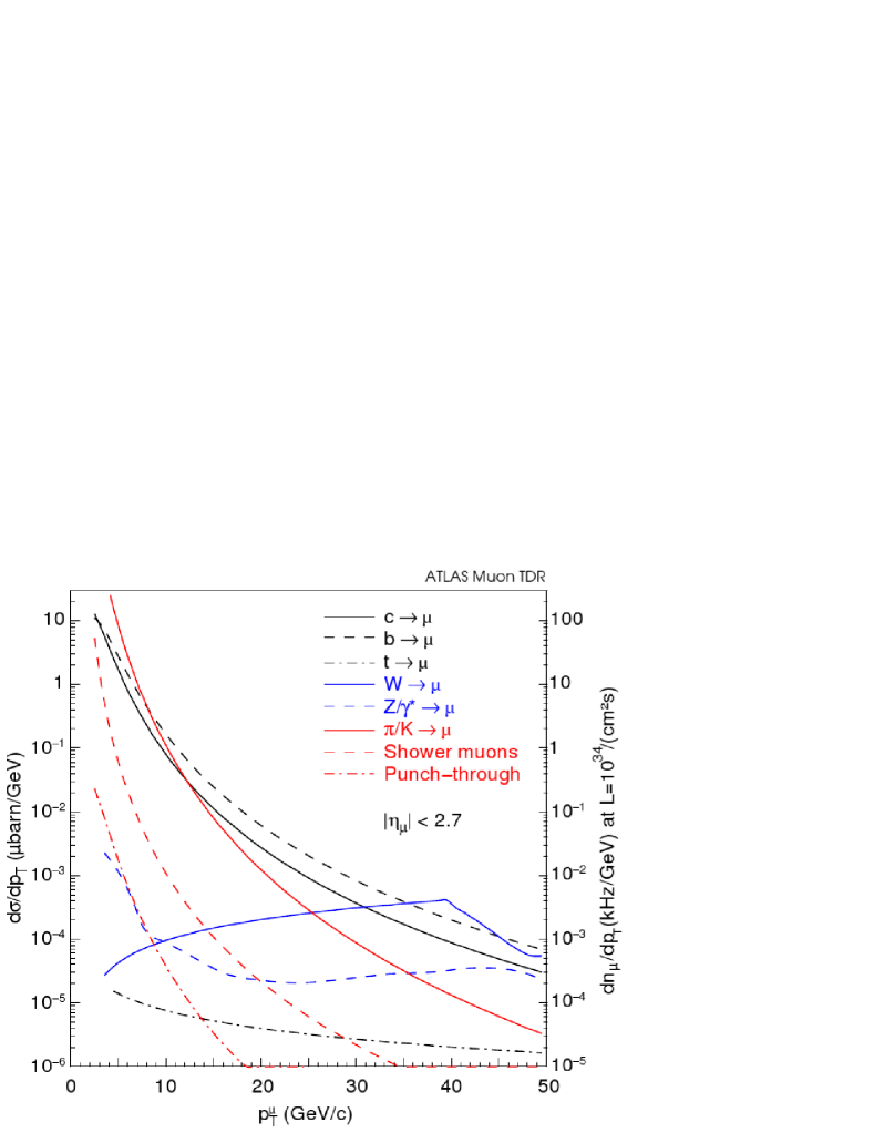
Many interesting physics processes with small cross sections have a signature of one (or more) muons above 20 GeV. The capability to trigger on high-pT tracks was therefore one of the principal requirements for the design of the ATLAS muon spectrometer [1, 2]. For this purpose a system of trigger chambers was implemented, covering the full acceptance of the muon detector, capable to detect tracks above a predefined pT within a sufficiently short latency to be used in the ATLAS Level-1 trigger. In the barrel and end-cap regions different chamber technologies were chosen, adapted to the different configurations of the magnetic field in these detector domains. In this article we describe the barrel region, where the Resistive Plate Chamber (RPC) technology is used.
2 Performance limits of RPC trigger chambers
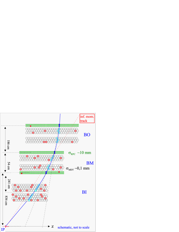
RPCs use pick-up strips perpendicular to z-direction (cf. Fig. 4 to sense the avalanches generated by traversing particles in the chamber gas, measuring the coordinates of the tracks along the bending direction of the magnetic field. The time resolution of about 20 ns of the RPC chambers is sufficient to tag the beam crossing with about 95 confidence. Fig. 2 shows the schematics of the Level-1 triggering system in the barrel region. RPC trigger chambers (marked in green) are positioned at three radial positions of the barrel, one in the outer detector layer (BO) and two in the middle layer (BM), below and above the middle MDT.
The slopes in the bending direction () of the track between inner and middle as well as between middle and outer RPC layer are compared to the slope of a track with infinite pT, i.e. a straight line coming from the interaction point (IP), the difference of the slopes being a measure of pT, where large deviations mean low pT, while tracks with small deviation from a straight line mean high pT. For the fast comparision of the slope of a track with the one of a infinite momentum track a system of coincidences between the pick-up strips of the three RPC layers is used (’coincidence matrices’).
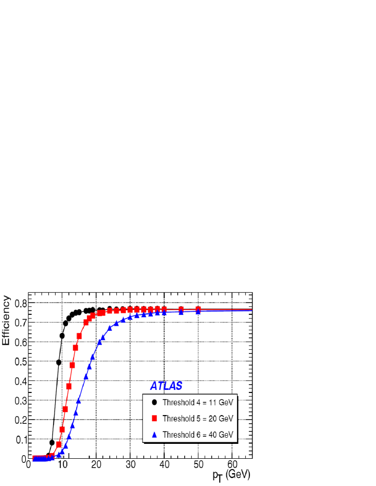
The width of the RPC strips of about 30 mm limits the precision of the slope measurement of the track. At a pT of 10, 20 and 40 GeV sagittas are 48, 24 and 12 mm, respectively, leading to a corresponding uncertainty of the threshold, as shown in Fig. 4. With a threshold setting of 20 GeV (red curve) the trigger is still accepting about 60 of the 15 GeV and 15 of the 10 GeV tracks and is thus not efficiently selecting the interesting physics events. Replacing the present RPC chambers by ones with higher spatial resolution would be an obvious solution. This costly conversion could be avoided, however, if the high spatial resolution of the nearby MDT chambers could be used for the Level-1 trigger. For this to happen, the transfer of information from the MDT to the Level-1 triggering system must be sufficiently fast to remain inside the overall ATLAS trigger latency.
The challenge for an improvement of the Level-1 trigger is to design a MDT readout scheme and an interface to the RPC trigger, able to deliver a refined pT-value inside the latency limits of the ATLAS trigger. The present latency budget of 2,5 s, adapted to the situation at the original LHC, is insufficient for any refinement of the trigger decision. For SLHC, however, an increase of the latency to 6,4 s or even 10 s will be implemented for the frontend data storage of all subdetectors, providing considerable design freedom for Level-1 trigger improvements.
3 Inclusion of the MDT precision chambers into the L1 decision
3.1 Towerwise structure of the Level-1 trigger
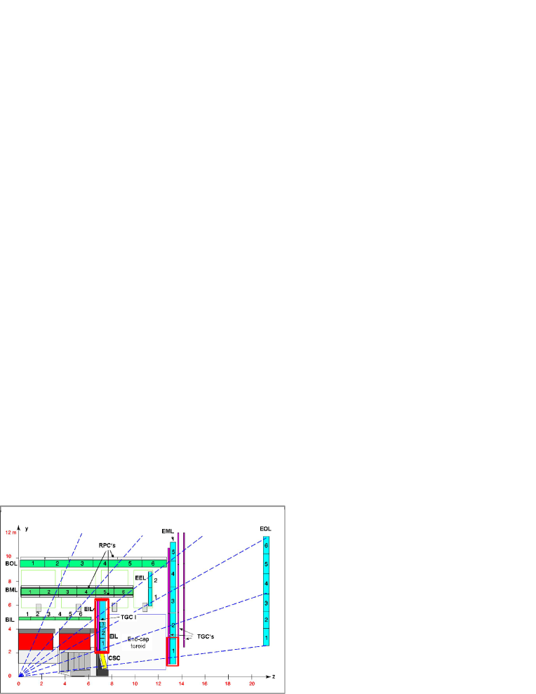
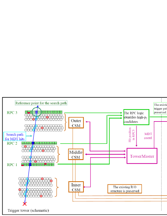
The muon spectrometer is partitioned in projective towers along the direction of pseudo rapidity and the azimuthal direction , where trigger and precision chambers are matched in size and location in each tower, see Fig. 4. High-pT tracks, following nearly straight lines, will mostly travel inside one projective tower, and therefore each tower can evaluate its high-pT triggers independently from neighbouring towers. The straight high-pT tracks define narrow search paths, where MDT hits, belonging to the triggering track must be located. The readout of the MDT chamber can therefore be limited to a small number of tubes along the track trajectory (see left part of Fig. 5). The search path is communicated from the RPC to the MDT via the coordinate of the track in the outer RPC.
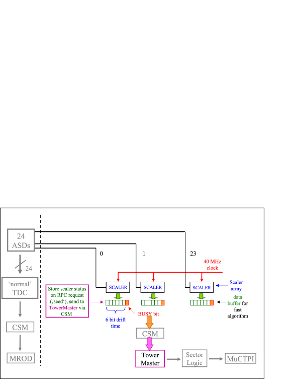
The present readout architecture of the MDT chambers is described in [3]. Being sequential and asynchroneous with the TTC, it is not suited for the Level-1 refinement. An additional, fast readout path of the MDT is therefore required, in parallel and independent of the existing one (see right part of Fig. 5). A simple scheme to have all drift times available at the same instant is shown in Fig. 6. Each of the 24 channels (i.e. tubes), served by a on-chamber readout card is connected to a scaler, which is started by each hit of the respective tube. If no trigger request is received from the RPC, the scaler goes into overflow and is automatically reset. If a request does arrive, all scalers are stopped, and the contents are transferred into a buffer for readout. Only the contents of scalers corresponding to tubes on the search path will be transferred to the TowerMaster for sagitta determination.
3.2 Interface between MDT and RPC
To interface the RPC logic with the MDT readout system a communication unit needs to be installed in each tower (”TowerMaster”). This unit needs to determine the explicite tube addresses along the search path (e.g. via a LUT) and send them to the on-chamber controllers of the MDTs, called Chamber Service Modules (CSM). The 3 CSMs, in turn, will read the drift times from the tubes on the search path and send them back to the TowerMaster. After reception of track co-ordinates from all 3 MDTs the TowerMaster could determine the sagitta, sending a confirm or a veto back to the RPC logic. Alternatively, all coordinates could be forwarded downstream to the Sector Logic in the Counting Room for confirmation or rejection.- The standard (’slow’) MDT readout would remain unchanged (brown arrows in Fig. 5).
3.3 Synchronization of the readout with the TTC clock
The fast readout will be strictly synchroneous with the TTC clock. This means that the RPC request (’seed’) for precision coordinates arrives at the MDT frontend a fixed number of beam crossings after the passage of the triggering muon. This way, due to the high time resolution of the RPC, the absolute drift times in the MDT tubes become known. This allows for a consistency check on the drift times in tubes subsequently traversed by the muon, i.e. the sum of drift times must be above a certain limit, otherwise the measurement might be corrupted by a preceeding conversion. This quality check of the drift time reading becomes particularly important at high background rates, where conversion events may occur at a high rate and may frequently degrade the drift time reading from a traversing muon.
3.4 Reduction of the drift time resolution
The resolution of the MDT drift time will be reduced from 12 to 6 bit, the corresponding position resolution of the MDT of about 1 mm (RMS) being still about a factor 10 better than the one of the RPC, sufficient for a decisive sharpening of the Level-1 trigger threshold. Corrections for the non-linear r–t relation in the MDT gas and other small effects can be neglected at this level of precision. With the reduction of the number of bits, data volumina and transmission delays are reduced. In addition, data redundancy and format overheads will be reduced to the strict minimum.
An analysis of the time behaviour of such a readout model shows that a latency of 4,5–5,5 s could be achieved and thus would be a realistic option for the upgrade of the muon Level-1 trigger for the SLHC. A significant advantage of this scheme would be that the existing RPC trigger chambers, except electronics, would not need any modifications.
A similar upgrade scheme could also be applied to the Level-1 trigger in the end-cap region where trigger chambers of the TGC type are used [1, 2]. Because of the different geometry of the toroidal magnetic field and the different location of trigger and MDT chambers, however, a modified architecture and specialized algorithms will have to be used.
4 Summary
The upgrade scheme for the Level-1 muon trigger described above allows to sharpen the threshold of the high-pT trigger by about an order of magnitude, sufficient for the luminosity increase envisioned for the SLHC. This way the existing RPC trigger chambers can stay in place. The readout electronics of RPC as well as MDT will need complete replacement. A number of readout units along the data path will have to be designed to contain local intelligence and the possibility for precise timing adjustment in order to fulfill the synchronicity requirement, mentioned above. Design, prototyping, production and installation will require a significant effort and a strong contribution from the ATLAS muon spectrometer community.
References
- [1] ATLAS Collaboration, Technical Design Report for the ATLAS Muon Spectrometer, CERN/LHCC/97-22, May 1997.
- [2] The ATLAS collaboration, The ATLAS Experiment at the CERN Large Hadron Collider, JINST 3 S08003 (2008)
- [3] Y. Arai et al., ATLAS Muon Drift Tube Electronics, JINST 3 P09001 (2008)