Thin-shell theory based analysis of radially pressurized multiwall carbon nanotubes
Abstract
The elastic radial deformation of multiwall carbon nanotubes (MWNTs) under hydrostatic pressure is investigated within the continuum elastic approximation. The thin-shell theory, with accurate elastic constants and interwall couplings, allows us to estimate the critical pressure above which the original circular cross-section transforms into radially corrugated ones. The emphasis is placed on the rigorous formulation of the van der Waals interaction between adjacent walls, which we analyze using two different approaches. Possible consequences of the radial corrugation in the physical properties of pressurized MWNTs are also discussed.
keywords:
carbon nanotube , high pressure , elastic deformation , radial buckling , van der Waals interaction1 Introduction
Nanomaterials are tiny platforms on which a beautiful interplay between structure and property can be appreciated. For the last decade, advanced nanofabrication techniques have put out various nanostructured materials with novel geometry [1, 2, 3, 4, 5], many of which exhibit unprecedented properties not seen in macroscopic structures. Among such nanostructures, carbon nanotubes have drawn great deal of attention. The salient feature of carbon nanotubes is their mechanical robustness and resilience [6]: Due to the extremely large stiffness, for instance, their thermal conductivity becomes higher than even that of diamond [7]. Besides, their flexibility in bending [8, 9], twisting [9, 10, 11, 12], radial compression [13, 14, 15, 16, 17], and the associated variations in the physical properties hold promise for developing nanoelectromechanical devices [18, 19]. Towards successful implementations of such ideas, computational studies have been playing a vital role in complementing experimental observations, often difficult and incomplete for nanomaterials [20].
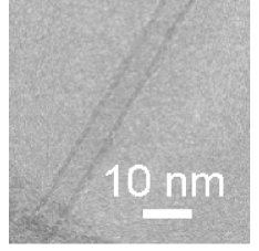
In view of structure-property relations, radial deformation is expected to elicit untouched behavior of multiwall carbon nanotubes (MWNTs); see Fig. 1 for a microscopic image of a typically synthesized MWNT [21]. The radial deformation disturbs both the equal spacings between the concentric walls in MWNTs and the in-plane hexagonal lattice within each wall. In particular, spatial modulation in the wall-wall separation may enhance (or hinder) the electron charge transfer between neighboring walls if they locally get close to (or pull away from) each other [22, 23]; this implies significant changes in various observables of MWNTs under external pressure. Despite the broad interest, theoretical efforts on the mechanics of radially pressurized MWNTs remain limited [24, 25, 26]. This scarcity is mainly because atomistic-based simulations of MWNTs having many walls are computationally very expensive.
In the present work, we employ a powerful alternative, the continuum elastic thin-shell theory approach, to analyze the stable cross-sectional shapes of MWNTs under hydrostatic pressure. Such approaches are often plagued with inaccurate or inconsistent elastic moduli. Here, we carefully select the intra-wall and wall-wall elastic constants for an accurate prediction of the critical pressure above which the original circular cross-section transforms into radially corrugated ones. In the corrugation modes, each wall exhibits a wavy structure in the circumferential direction along the tube axis. Such the pressure-induced corrugation is attributed to the mismatch in the mechanical stability between the flexible outmost walls with large tube diameters and rigid innermost walls with small diameters.
2 Methods
2.1 Mechanical energy
Although atomistic simulations may provide precise estimations of physical quantities in general, they often demand huge computational resources in systems of interest. On this background, the thin shell theory based analysis for the carbon nanotube mechanics has long been developed [13, 27, 28, 29, 30, 31]. Along the continuum thin-shell method, a MWNT is mapped onto a set of continuum elastic hollow tubes of radii (). A point on the circle corresponding to the cross-section of the th tube is described by in terms of the polar coordinates; is the circumferential angle around the tube axis. Under pressure , the point moves to
| (2) | |||||
If the deformation amplitudes, and , are sufficiently small, the mechanical energy of the th tube per unit axial length is given by
| (3) |
Here, and are respectively the in-plane and bending strains of the th wall, both depending on , and their derivatives with respect to [32]. The constant denotes the in-plane stiffness, the flexural rigidity, and the Poisson ratio of each wall.
For quantitative discussions, the values of and must be carefully determined. In the conventional thin-shell theory for macroscopic objects, and are related to the Young’s modulus of the wall and its thickness as , . However, for carbon nanotubes, the wall is made out of a monoatomic graphitic layer and consequently the notion of a wall thickness becomes elusive. Hence, the macroscopic relations for and noted above fail since there is no unique way of defining the thickness of the graphene wall [33]. Thus the values of and should be evaluated ab-initio from direct measurements or computations of carbon sheets, without reference to the macroscopic relations. In actual calculations, we substitute nN/nm, nN nm, and along with the prior work [28] based on the density functional theory. It should be noted that the values of and are essentially tube-diameter dependent. Neverthelss, such the dependences become negligible when the tube diameter exceeds 1 nm, above which the elastic constants of carbon nanotubes converge to those of a planar graphene sheet [28]. On this background, we will take into account only the nanotubes whose diameters are larger than 1 nm, which allows to fix the values of and as noted above.
The stable cross-sections of MWNTs under minimize the mechanical energy of the whole system that is described by [34]
| (4) |
where
| (5) |
and
| (6) |
with . The term accounts for the van der Waals (vdW) interaction energy of adjacent pairs of walls, and is the negative of the work done by during cross-sectional deformation. Note that is a functional of and ; therefore, the variational method allows to obtain the optimal solutions of and that minimize under a given .
For , the outside walls have large diameters, and consequently are very flexible and susceptible to mechanical instabilities under radial pressure. The contrast in the radial rigidity between the outermost walls and the innermost ones triggers a non-trivial cross-sectional deformation observed in radially pressurized MWNTs. In fact, the linearized buckling analysis leads to the conclusion that immediately above a critical pressure , the circular cross section of MWNTs becomes radially deformed as described by [34]
| (7) |
The solution (7) represents a wavy structure of a MWNT’s cross-section, called the radial corrugation with a mode index . The integer indicates the wave number of the corrugated walls, being uniquely determined by the one-to-one relation between and [34]. We will find below that depends systematically on and the innermost tube diameter as presented in Fig. 3.
2.2 Wall-wall interaction coefficient
It is known that in the axial buckling of MWNTs, the buckling load is sensitive to the vdW interaction between adjacent walls [35]. Likewise, is thought to depend on the strength of vdW interactions; this is the reason why we address the rigorous formulation of the interaction. Using both a discrete-pairwise summation and a continuum approach, we derive the coefficients in Eq. (5) through a first order Taylor approximation of the vdW pressure [35, 36] associated with the vdW potential . Here, is the distance between a pair of carbon atoms, is the equilibrium distance between two interacting atoms, and is the well depth of the potential [37]. The resulting equilibrium spacing between neighboring walls, used here to define the geometry of the MWNCTs, is . The derivative is the force between the two atoms.
There exist several continuum models for the vdW interactions [35, 36, 37]. In Ref. [35], expressions for the pressure and the vdW interaction coefficients were obtained by integrating the continuum vdW force and its derivative on curved wall surface, while disregarding the vectorial nature of the force. The significance of the vectorial nature of the force was addressed in Ref. [36], where analytical expressions for the vdW pressure were obtained by considering only the component of the vdW force normal to the wall. It was emphasized in Ref. [36] that for a two-walled carbon nanotube, the pressure exerted on inner wall is different from the pressure on the outer wall. The pressures on the inner and outer walls for a concentric two-walled tube with radii and are given below (with positive signs for compression):
| (8) |
where with nm-2 being the area density of carbon atoms. We used the notations:
| (9) |
where , , , and .

In the following, we obtain analytical expressions for linearizing the formula (8) for the pressure. The formula takes into account correctly the normal-to-wall component of vdW forces, and avoids common assumptions like [29] and [38]; therefore, the resulting will be also free from unnecessary assumptions.
In the present work, infinitesimal deformation is considered. Hence, the linearzed pressure is needed for vdW energy calculation. Note that the vdW energy depends quadratically on the change in spacing between two adjacent walls. Consider two consecutive walls with radii and , where the subscripts and correspond to and respectively. The vdW energy stored due to symmetric perturbation along the positive direction of pressure is given by
| (10) |
where is the mean radius and is the vdW pressures on the th wall. The corresponding linearized pressure is given by . In Eq. (10), describes the length of the infinitesimal element on which the pressure is acting. Using the linearized pressure and comparing with Eq. (5), we get the expressions for vdW coefficients as
| (11) |
where
| (12) |
See Appendix for the derivatives of . Note that the is symmetric.
These analytical expressions for the stiffness coefficients associated with the vdW interactions obtained with the continuum approximation are compared with the coefficients obtained using a discrete pairwise calculation. In the later approach, the pressure coefficients are computed by summing the component normal to the wall of the linearized vdW forces acting on an atom , i.e. the normal component of , where the linearized force is evaluated at the actual distance between the pair of interacting atoms and , . In Ref. [35], the linearization is done at the equilibrium distance of the potential. Noting that most of the interacting atom pairs are not at the equilibrium distance, it is apparent that the linearization should be done at the actual distance between each pair of interacting atoms. The discrete pressure can be obtained by dividing the force exerted on one atom by the area per atom. The vdW force on one atom is obtained by considering the interactions between this atom with all the atoms on a neighboring wall. The effect of the relative lattice placement of interacting walls is averaged out by integrating the interactions over a symmetric triangle of the representative hexagonal cell of graphene.
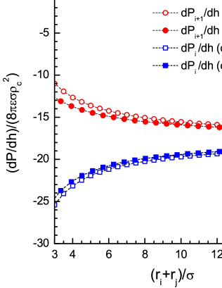
The normalized pressure derivatives and normalized vdW interaction coefficients are plotted against normalized radius in Fig. 2. A good match is observed between the discrete-pairwise and the continuum approach. The interaction coefficient for two horizontally placed graphene walls, , is obtained from the second derivative of the analytic continuum interaction potential [37]. For larger radii, approaches to , corroborating our results for nanotubes.
3 Results and discussion
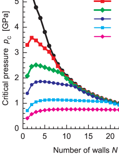
Figure 3 plots as a function of for various values of . An initial increase in at small (except for nm) is attributed to the enhancement of radial stiffness of the entire MWNT by encapsulation. This stiffening effect disappears with further increase in , resulting in decay or convergence of . It is noteworthy that MWNTs practically synthesized often show larger than those presented in Fig. 3. In fact, the MWNT depicted in the image of Fig. 1 gives nm, for which lies at several hundreds of MPa as estimated from Fig. 3. Such degree of pressure applied to MWNTs is easily accessible in high-pressure experiments, supporting the feasibility of our theoretical predictions. The -dependence of for various fixed is provided in Fig. 4 in a normalized manner; When , we obtain in agreement with previous studies on single-walled nanotubes [13, 39]. It also deserves comment that a radial pressure large enough to cause corrugation can be achieved by electron-beam irradiation; the self-healing nature of eroded carbon walls gives rise to a spontaneous contraction that exerts a high pressure on the inner walls [40, 41, 42]
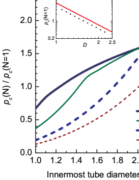
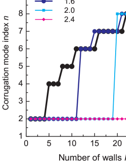
Figure 5 shows the stepwise increases in the corrugation mode index , defined by Eq. (7). For all , the deformation mode observed just above abruptly increases from to at a certain value of , followed by the successive emergence of higher corrugation modes with larger . These successive transitions in at originate from the mismatch in the radial stiffness of the innermost and outermost walls. A large discrepancy in the radial stiffness of the inner and outer walls results in a maldistribution of the deformation amplitudes of concentric walls interacting via vdW forces, which consequently produces an abrupt change in the observed deformation mode at a certain value of .
A possible physical consequence of radial corrugation is a pressure-driven change in quantum transport of carriers in radially corrugated nanotubes. It is known that mobile carriers whose motion is confined to a thin curved layer behave differently from those on a conventional flat plane because of the curvature-induced electromagnetic field [43, 44, 45]. Another interesting issue is the effect of atomic lattice registry on non-linear deformation (i.e. large deformation amplitude) regimes [46, 47, 48]. In the latter case, the degree of commensurance in atomic structures between neighboring carbon layers plays a prominent role in determining the optimal morphology of highly corrugated MWNTs, in which the interwall spacings partially vanish. Crumpling or twisting caused by radial pressure is expected, and in fact were observed in preliminary calculations [49].
4 Conclusion
The thin-shell theory has been employed to derive the critical hydrostatic pressure above which the cross section of pressurized MWNTs transforms into radially corrugated patterns. The value of lies on the order of several hundreds of MPa for practically synthesized MWNTs with and nm, indicating the experimental feasibility of the prediction. The enegetically favored corrugation pattern strongly depends on and , where a larger and smaller give a larger corrugation mode index . Our results provide a clue in developing MWNT-based devices operating under high pressure.
Acknowledgement
We acknowledge M. Rahimi, E. Osawa, Y. Suda, K. Yakubo and T. Mikami for helpful discussions. HS is thankful for the financial supports provided by KAKENHI and Hokkaido Gas Co., Ltd. SG acknowledges the support of the Spanish Ministry of Science and Innovation through the Juan de la Cierva program. MA acknowledges the support of the European Research Council (FP7/2007-2013)/ERC grant agreement nr 240487 and the prize “ICREA Academia” funded by the Generalitat de Catalunya. Numerical simulations were partly carried out using the facilities of the Supercomputer Center, University of Tokyo.
Appendix A Functional forms of
References
- [1] S. Tanda, T. Tsuneta, Y. Okajima, K. Inagaki, K. Yamaya and N. Hatakenaka, Nature 417 (2002) 397.
- [2] M. Ozawa, H. Goto, M. Kusunoki and E. Osawa, J. Phys. Chem. B 106 (2002) 7135.
- [3] J. Onoe, T. Nakayama, M. Aono and T. Hara, Appl. Phys. Lett. 82 (2003) 595.
- [4] Y. Tatewaki, T. Hatanaka, R. Tsunashima, T. Nakamura, M. Kimura and H. Shirai, Chem. Asian J. 4 (2009) 1474.
- [5] V. Saranathan, C. O. Osuji, S. G. J. Mochrie, H. Noh, S. Narayanan, A. Sandy, E. R. Dufresne and R. O. Prum, PNAS 107 (2010) 11676.
- [6] H. Shima and M. Sato, Elastic and Plastic Deformation of Carbon Nanotubes, (Pan Stanford Pub., 2011) in press.
- [7] P. Kim, L. Shi, A. Majumdar and P. L. McEuen, Phys. Rev. Lett. 87 (2001) 215502.
- [8] A. Sears and R. C. Batra, Phys. Rev. B 69 (2004) 235406.
- [9] I. Arias and M. Arroyo, Phys. Rev. Lett. 100 (2008) 085503; M. Arroyo and I. Arias, J. Mech. Phys. Solids 56 (2008) 1224.
- [10] X. Huang, J. Zou and S. Zhang, Appl. Phys. Lett. 93 (2008) 031915; J. Zou, X. Huang, M. Arroyo and S. Zhang, J. Appl. Phys. 105 (2009) 033516.
- [11] D. B. Zhang, R. D. James and T. Dumitricǎ, Phys. Rev. B 80 (2009) 115418.
- [12] F. Khademolhosseini, R. K. N. D. Rajapakse and A. Nojeh, Comp. Mater. Sci 48 (2010) 736.
- [13] B. I. Yakobson, C. J. Brabec, and J. Bernholc, Phys. Rev. Lett. 76 (1996) 2511.
- [14] I. Palaci, S. Fedrigo, H. Brune, C. Klinke, M. Chen, and E. Riedo, Phys. Rev. Lett. 94 (2005) 175502.
- [15] C. Gómez-Navarro, J. J. Sáenz, and J. Gómez-Herrero, Phys. Rev. Lett. 96 (2006) 076803.
- [16] A. P. M. Barboza, A. P. Gomes, B. S. Archanjo, P. T. Araujo, A. Jorio, A. S. Ferlauto, M. S. C. Mazzoni, H. Chacham and B. R. A. Neves, Phys. Rev. Lett. 100 (2008) 256804.
- [17] E. M. Diniz, R. W. Nunes, H. Chacham and M. S. C. Mazzoni, Phys. Rev. B 81 (2010) 153413.
- [18] L. X. Dong, A. Subramanian and B. J. Nelson, Nano Today 2 (2009) 12.
- [19] S. Roy and Z. Gao, Nano Today 4 (2009) 318.
- [20] H. Rafii-Tabar, Computational Physics of Carbon Nanotubes, (Cambridge Univ. Pr., 2007)
- [21] A. Okita, Y. Suda, A. Oda, J. Nakamura, A. Ozeki, K. Bhattacharyya, H. Sugawara, and Y. Sakai, Carbon 45 (2007) 1518.
- [22] V. Zólyomi, J. Koltai, Á. Rusznyák, J. Kürti, Á. Gali, F. Simon, H. Kuzmany, Á. Szabados and P. R. Surján, Phys. Rev. B 77 (2008) 245403.
- [23] M. Ahlskog, O. Herranen, A. Johansson, J. Leppäniemi and D. Mtsuko, Phys. Rev. B 79 (2009) 155408.
- [24] Z. Xu, L. Wang, and Q. Zheng, Small 4 (2008) 733.
- [25] S. H. Yang, L. L. Feng and F. Feng, J. Phys. D: Appl. Phys. 42 (2009) 055414.
- [26] X. Huang, W. Liang and S. Zhang, Nanoscale Res. Lett. 6 (2011) 53.
- [27] C. Q. Ru, Phys. Rev. B 62 (2000) 16962.
- [28] K. N. Kudin, G. E. Scuseria, and B. I. Yakobson, Phys. Rev. B 64 (2001) 235406.
- [29] A. Pantano, D. M. Parks, and M. C. Boyce, J. Mech. Phys. Solid. 52 (2004) 789.
- [30] Y. Huang, J. Wu, and K. C. Hwang, Phys. Rev. B 74 (2006) 245413.
- [31] K. Chandraseker and S. Mukherjee, Comp. Mater. Sci. 40 (2007) 147.
- [32] J. L. Sanders Jr., Quart. Appl. Math. 21 (1963) 21.
- [33] S. S. Gupta, F. G. Bosco and R. C. Batra, Comp. Mater. Sci. 47 (2010) 1049, and references therein.
- [34] H. Shima and M. Sato, Nanotechnology 19 (2008) 495705; Phys. Stat. Sol. A 206 (2009) 2228.
- [35] X. Q. He, S. Kitipornchai and K. M. Liew, J. Mech. Phys. Solids 53 (2005) 303.
- [36] W. B. Lu, B. Liu, J. Wu, J. Xiao, K. C. Hwang, S. Y. Fu, and Y. Huang, Appl. Phys. Lett. 94 (2009) 101917.
- [37] L. A. Girifalco, M. Hodak, and R. S. Lee, Phys. Rev. B 62 (2000) 13104.
- [38] C.Q. Ru, J. Mech. Phys. Solids, 49 (2001) 1265.
- [39] D. Y. Sun, D. J. Shu, M. Ji, F. Liu, M. Wang, and X. G. Gong, Phys. Rev. B 70 (2004) 165417.
- [40] F. Banhart and P. M. Ajayan, Nature 382 (1996) 433.
- [41] L. Sun, F. Banhart, A. V. Krasheninnikov, J. A. Rodríguez-Manzo, M. Terrons, and P. M. Ajayan, Science 312 (2006) 1199.
- [42] H. Shima, M. Sato, K. Iiboshi, S. Ghosh and M. Arroyo, Phys. Rev. B 82 (2010) 085401.
- [43] H. Shima, H. Yoshioka and J. Onoe, Phys. Rev. B 79 (2009) 201401(R); Physica E 42 (2010) 1151; H. Shima, S. Ono and H. Yoshioka, Eur. Phys. J. B 78 (2010) 481.
- [44] S. Ono and H. Shima, Phys. Rev. B 79 (2009) 235407; Physica E 42 (2010) 1224; J. Phys. Soc. Jpn. (2011) in press.
- [45] H. Taira and H. Shima, J. Phys.: Condens. Mat. 22 (2010) 075301; ibid., 22 (2010) 245302; J. Phys. A: Math. Theor. 43 (2010) 354013.
- [46] M. F. Yu, M. J. Dyer, J. Chen, D. Qian, W. K. Liu and R. S. Ruoff, Phys. Rev. B 64 (2001) 241403.
- [47] B. Liu, M. F. Yu and Y. G. Huang, Phys. Rev. B 70 (2004) 161402.
- [48] N. Marom, J. Bernstein, J. Garel, A. Tkatchenko, E. Joselevich, L. Kronik and O. Hod, Phys. Rev. Lett. 105 (2010) 046801.
- [49] M. Rahimi, M. Arroyo, H. Shima and M. Sato, unpublished.