Elastic instability in stratified core annular flow
Abstract
We study experimentally the interfacial instability between a layer of dilute polymer solution and water flowing in a thin capillary. The use of microfluidic devices allows us to observe and quantify in great detail the features of the flow. At low velocities, the flow takes the form of a straight jet, while at high velocities, steady or advected wavy jets are produced. We demonstrate that the transition between these flow regimes is purely elastic – it is caused by viscoelasticity of the polymer solution only. The linear stability analysis of the flow in the short-wave approximation captures quantitatively the flow diagram. Suprisingly, unstable flows are observed for strong velocities, whereas convected flows are observed for low velocities. We demonstrate that this instability can be used to measure rheological properties of dilute polymer solutions that are difficult to assess otherwise.
pacs:
83.80.Rs, 83.60.Wc, 83.85.CgPolymer solutions exhibit purely elastic flow instabilities even in the absence of inertia Larson:92 . The almost ubiquitous ingredient of such an elastic instability is the curvature of streamlines: polymers that have been extended along curved streamlines are taken by fluctuations across shear rate gradient in the unperturbed state which, in turn, couples the hoop stresses acting along the curved streamlines to the radial and axial flows and amplifies the perturbation Shaqfeh:96 ; McKinley:96 . Flat interfaces between two fluids with different viscoelastic properties can also become unstable Chen:91 ; Hinch:92 ; Wilson:97 due to the normal stress imbalance across the interface. These instabilities often occur in coextrusion where different polymers are melted in separate screw extruders and then flown simultaneously in the extrusion nozzle. Undesirable wavy interfaces are sometimes observed between the adjacent polymer layers both during the flow and in the final product Valette:04 . Since these instabilities set severe limits to the industrial processes such as film or fiber fabrication, they have been extensively studied before Valette:04 ; Valette:03 . Although previous experiments and theory agree reasonably well Han:78 ; Valette:04 , a comprehensive description of the flow is still lacking Valette:04a .
In this Letter we propose a quantitative explanation for various flow patterns observed in purely elastic interfacial instabilities. We perform a set of original experiments on co-flow of a polymer solution and water and map the full flow diagram. In contrast to previous experimental studies dealing with macroscopic flows of molten polymers, we focus here on flows of dilute polymer solutions and water in microfluidic devices. The advantage of using dilute polymer solutions is that their elastic properties can easily be tuned by dilution and that most of the theoretical work has been performed for models representing dilute polymeric fluids. The use of microfluidic flow geometries offers simple control and visualisation of the flow.
We observe that above some flow rate the interface between the polymer solution and water becomes wavy. Surprisingly, for relatively low velocities, the instability is convected downstream, while a stationary unstable flow is observed at high velocities. This behaviour is due to the interplay between advection by the mean flow and the growth of a perturbation and is in close agreement with the model we propose. Our work opens the route to use such an elastic instability in straight channels to promote mixing in microfluidic devices Helton:07 . We demonstrate that it is also a new way to measure rheological properties of weakly elastic polymer solutions where very few techniques are available.
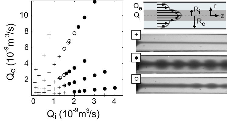
Our experiments are performed in a microfluidic device made of nested glass capillaries: an inner capillary of square cross-section with tapered nozzle (section ) nearly perfectly fits into a cylindrical capillary () that carries the outer fluid; it offers a simple way to self-center and align the capillaries utada:05 ; Guillot:07 . The length between the nozzle and the outlet of the device is set to . The two co-flowing fluids are injected with precision syringe pumps at flow rates and for the internal and external rates respectively. The microfluidic chip is positioned vertically on a standard microscope (mounted accordingly) in order to prevent the effect of gravity. The observations are carried out with a fast camera (Miro Phantom). Our working fluid is a solution of Poly(VinylAlcohol) (PVA) of molar mass in water at concentrations of , , and wt/wt (for which wt/wt). The measured values of the shear viscosity of the solutions are given in Table 1 and do not depend on the shear rate up to . The viscosity of water is taken to be at 20 °C.
We observe flow patterns that depend strongly on the flow rates. Fig. 1 shows a typical flow diagram in the (, ) plane for water and the semi-dilute PVA solution as the inner and outer fluids, respectively. For low flow rates, we find straight jets (+) that extend up to the outlet of the device, while at higher flow rates the interface between the two fluids becomes unstable. At intermediate flow rates, jets are straight from the inlet up to some distance downstream where varicose undulations set in. We call them advected wavy jets () and note that this distance decreases with the flow rates. At yet higher flow rates, jets are wavy through the whole set-up (). We note here that the advected wavy and wavy jets are, most probably, the same dynamical state, the only difference is that the latter sets in before and former after some arbitrary lengthscale . We distinguish between the two states in order to be able to measure the relaxation time of the polymer solution, as will become apparent later. Unless mentioned otherwise, we set .
In order to identify the origin of the instability, we first calculate the laminar flow profile in the system. We neglect both inertial effects and molecular diffusion processes since the Reynolds number is small () and the Péclet number is large () in our experiments. The two miscible fluids thus flow side by side without mixing and exhibit a constant effective surface tension Korteweg:01 . The motion of water is then described by the Stokes equation while the polymer solution obeys the Oldroyd-B model bird :
| (1) | |||
where is the upper-convected derivative bird . Here, is the velocity and is the pressure in the fluid, is the polymer contribution to the stress tensor; is the viscosity of the solvent, and and are the Maxwell relaxation time of the polymer and the increase of viscosity due to the polymer chains respectively. The total shear viscosity of the polymeric solution is thus . We enforce no-slip boundary conditions at the solid-liquid interface and the continuity of the velocity and of the tangential stress at the interface between the two fluids. In the unidirectional laminar flow of Fig. 1, the pressure drop between the nozzle and the outlet of the capillary is the same in both fluids and is related by Eqs. (Elastic instability in stratified core annular flow) to the flow rates and the relative position of the interface between the two fluids :
| (2) |
where , , and is the viscosity ratio.
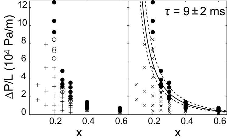
In the left part of Fig. 2 we redraw our experimental data in the () plane and observe that stable flows occur at low while unstable flows occur at high pressure drops. This observation allows us to dismiss the Rayleigh-Plateau mechanism as a possible origin of the instability that would be triggered by the effective surface tension between the two miscible fluids Korteweg:01 ; Petitjeans:96 . Indeed, this would be contradictory to recent experimental and theoretical results Guillot:07 that explicitly demonstrate that droplets and wavy jets (absolutely unstable states) occur at low pressure drops while straight jets dominate at high pressure drops.
We also exclude the viscosity stratification of the flow as an origin of the instability Hickox:71 ; dOlce:09 . We have repeated the same experiment with a glycerin solution with and we have never observed unstable inferfaces. Since the viscosity-contrast based instability is of inertial origin, it should develop at higher Reynolds numbers. However, it does not play a role at our flow conditions.
We are thus left with a purely elastic instability driven by the constrast of the normal stresses across the interface Hinch:92 . This instability was studied analytically by Chen Chen:91 and by Chen and Joseph Chen:92 assuming low Reynolds and high Péclet numbers as in Eq. (2). They performed the linear stability analysis of the flow with respect to small axisymmetric perturbations with being the complex growth rate and setting the wavelength of the perturbation. They found that long-wavelength perturbations are always stable Chen:91 . In the opposite limit , the flow is always unstable Chen:92 and for weak elasticity of the solution, the dispersion relation can be approximated by:
| (3) |
An important feature of this dispersion relation is that the real part of the growth rate is independent of the wavelength. Full numerical linear stability analysis (to be published elsewhere) confirms that the dispersion curve is practically flat and positive only becoming negative for very small ’s. This implies that almost all wavelengths become unstable with an identical growth rate and the question of the wavelength selection cannot be answered based on the linear theory. Intriguingly, the use of a more complex rheological model would permit to raise this degeneracy Valette:04 .
In order to describe the convective nature of the instability we propose a simple kinetic criterion that captures most of our experimental observations. We assume that the instability sets in very close to the nozzle and is growing on the typical timescale while being advected downstream with the velocity of the interface . The typical development length of the instability is then , and the boundary between the advected wavy and wavy jets is given by . In terms of the applied experimental parameters, this criterion reads:
| (4) |
This criterion offers a few interesting predictions. First, the dependence upon the pressure drop is quite surprising. Eq. (4) implies that for a given ratio of the flow rates (which is independent of ), the advected wavy jets () occur at low pressure drops, while the wavy jets () should occur at high pressure drops, as observed experimentally. Since the velocity of the interface scales linearly with the pressure drop while the destabilising forces due to the viscoelastic normal stresses scale as bird , the instability moves closer to the inlet upon increase of the pressure drop. This is in contrast with the Rayleigh-Plateau instability due to the surface tension for which the opposite order of dynamical states is observed Guillot:07 . Moreover, the higher the pressure drop, the smaller the polymer relaxation time must be to reach the condition , that turns out to be a fruitful way to measure , as we show below. We also note that this is a purely elastic instability as it vanishes in the Newtonian limit . Finally, we observe that the criterion (4) is indepedent of the size of the capillary that suggests that this instability will also exist in nanofluidic or macrofluidic devices provided the inertial forces are kept small.
We now compare this kinetic criterion to our experiments. The only unknown quantity in (4) is the polymer relaxation time and we first use it as a fitting parameter. The right panel of Fig. 2 shows that the theory based on the single-relaxation time Oldroyd-B model agrees reasonably well with the experiments. For the solution we have extracted . Some discrepancy however is apparent at small radii of the Newtonian core . One possible source of the discrepancy is the approximate nature of the dispersion relation (3). It is derived for short-wavelength perturbations while we use it for disturbances of intermediate wavelength. This only makes sense if the actual dispersion relation is flat for most of the ’s. The full numerical linear stability analysis shows that for small the dispersion relation is less flat than for large values of which possibly explains the discrepancy between theory and experiments in Fig. 2. Another possibility is that at small we observe a decrease of the relaxation time with the local shear rate (small correspond to large pressure drops and thus high shear rates at the interface).
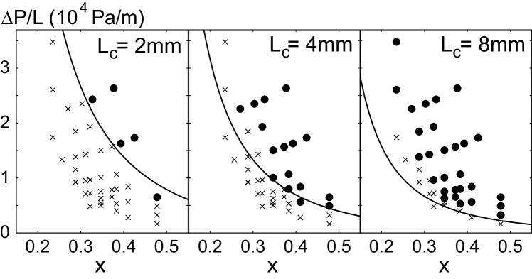
Next we show that the model is actually self-consistent as the measurement of is quite insensitive to the choice of . In Fig. 3 we plot the stability diagram of the same system with various reference distances . A single value of the polymer relaxation time is able to reasonably fit most of the data. Once again, the discrepancies at small are probably due to the reasons mentioned above.
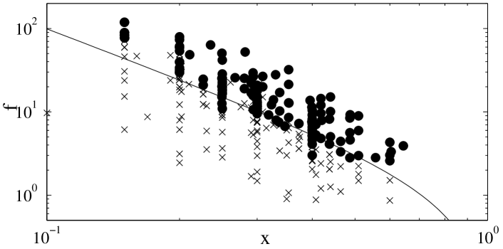
The experimental results for several polymer solutions are summarised on the master phase diagram in Fig. 4. Clearly, the simple criterion (4) is remarkably successful in predicting the transition between advected wavy and wavy jets. In Table 1 we provide the values of extracted for several concentrations of the polymer. To check these values, independent measurements of the polymer relaxation time have been performed. First, we use a version of extensional rheometry described by Amarouchene et al. Amarouchene:01 . When a drop of a polymer solution detaches from a capillary tube, a long-lived cylindrical neck is formed. Initially, it thins according to a power law for all liquids, and then further, exponentially in time if the liquid is viscoelastic. The decay time of the exponential thinning is directly proportional to the characteristic time of the polymer . We have also performed conventional rheological measurements of the polymer relaxation time. The data are quite noisy since the solutions are not very viscous and only weakly elastic. In Table 1 we report the values measured at the shear rate of which is similar to the shear rates in our coflow experiments. These values are in a reasonable agreement with the values extracted from the onset of wavy stationary jets. Conventional rheometry also shows that the polymer relaxation time is a decreasing function of the shear rate providing support for our explanation of the discrepancies in Figs. 2 and 3.
| wt% | ( Pa ⋅ s ) | ( m s ) | ( m s ) | ( m s ,) |
|---|---|---|---|---|
| 7.5 | 0.65 | 12020 | 70 20 | 100 |
| 6 | 0.25 | 60 10 | 20 10 | |
| 5 | 0.1 | 9 2 | 15 10 | 12 |
| 3.25 | 0.04 | 8 2 |
In this Letter, we have demonstrated that the purely elastic interfacial instability that exists between two fluids with different viscoelastic properties can not only be explained on a kinetic basis but also used to measure the polymer relaxation time in weakly elastic polymer solutions which is quite difficult to obtain otherwise. The technique also has the potential to measure shear-thinning of the solution at high shear rates. We have performed the fitting procedure described above independently for every and thus obtained the curve vs shear rate. The results look promising and presently we are working on the extension of the technique to more complicated constitutive relations than the Oldroyd-B model that will allow us to extract full non-linear rheology even for very dilute polymer solutions.
We would like to thank Dr. Christian Wagner and Christof Schafer, Saarland University, for their help with the rheometry. AM acknowledges support from the Royal Society of Edinburgh/BP Trust Personal Research Fellowship and EPSRC Career Acceleration Fellowship (grant reference number EP/I004262/1). LOF acknowledges support from the Aquitaine Council and from ANR Pnano project MicRheo.
References
- (1) R. G. Larson, Rheo. Acta 31, 213 (1992)
- (2) E. S. G. Shaqfeh, Annu. Rev. Fluid Mech. 28, 129 (1996)
- (3) G. McKinley, P. Pakdel, and A. Oztekin, J. Non-Newton. Fluid Mech. 67, 19 (1996)
- (4) K. P. Chen, J. Non-Newton. Fluid Mech. 40, 155 (1991)
- (5) E. J. Hinch, O. J. Harris, and J. M. Rallison, J. Non-Newton. Fluid Mech. 43, 311 (1992)
- (6) H. J. Wilson and J. M. Rallison, J. Non-Newton. Fluid Mech. 72, 237 (1997)
- (7) R. Valette, R. Laure, Y. Demay, and J. F. Agassant, Int. Polym. Process. 19, 118 (2004)
- (8) R. Valette, R. Laure, Y. Demay, and J. F. Agassant, Int. Polym. Process. 18, 171 (2003)
- (9) C. D. Han and R. Shetty, Pol. Eng. Sci. 18, 180 (1978)
- (10) R. Valette, P. Laure, Y. Demay, and J. F. Agassant, Journal of Non-Newtonian Fluid Mechanics 121, 41 (2004)
- (11) K. L. Helton and P. Yager, Lab. Chip 7, 1581 (2007)
- (12) A. Utada, E. Lorenceau, D. Link, P. Kaplan, H. A. Stone, and D. Weitz, Science 308, 537 (2005)
- (13) P. Guillot, A. Colin, A. S. Utada, and A. Ajdari, Phys. Rev. Lett. 99, 104502 (2007)
- (14) D. J. Korteweg, Arch. Neerl. Sci. Ex. Nat. II (1901)
- (15) R. B. Bird, C. F. Curtiss, R. C. Armstrong, and O. Hassager, Dynamics of polymeric liquids, 2nd ed., Vol. 1. Fluid Mechanics (Wiley, New York, 1987)
- (16) P. Petitjeans, C. R. Acad. Sci. 322, 673 (1996)
- (17) C. E. Hickox, Phys. Fluids 14, 251 (1971)
- (18) M. d’Olce, J. Martin, N. Rakotomalala, D. Salin, and L. Talon, J. Fluid Mech. 618, 305 (2009)
- (19) K. Chen and D. D. Joseph, J. Non-Newton. Fluid Mech. 42, 189 (1992)
- (20) Y. Amarouchene, D. Bonn, J. Meunier, and H. Kellay, Phys. Rev. Lett. 86, 3558 (Apr 2001)