Evanescent Gain in “Trapped Rainbow” Negative Refractive Index Heterostructures
Abstract
We theoretically and numerically analyze a five-layer “trapped rainbow” waveguide made of a passive negative refractive index (NRI) core layer and gain strips in the cladding. Analytic transfer-matrix calculations and full-wave time-domain simulations are deployed to calculate, both in the frequency- and in the time-domain, the losses or gain experienced by complex-wavevector and complex-frequency modes. We find an excellent agreement between five distinct sets of results, all showing that the use of evanescent pumping (gain) can compensate the losses in the NRI slow-light regime.
The ability to stop and store optical pulses could usher in a range of fundamentally new and revolutionary applications Milonni ; Khurgin , but the challenges encountered in our efforts to stop light are formidable. This highly unusual state for an electromagnetic wave refers to the situation where the lightwave completely stops despite the absence of any dielectric or other barriers in the directions where it could propagate. Unlike the confinement or trapping of light inside a dielectric cavity, where one cannot spatially separate optical bits of information, a stopped-light structure would allow for sequentially stopping and storing spatially separated optical bits, thereby potentially leading to all-optical memories Milonni ; Khurgin . Unfortunately, stopping of light cannot be obtained with (non-switchable) periodic structures, such as photonic crystals or coupled-resonator optical waveguides, owing to their extreme sensitivity to disorder, which invariably destroys the zero-group-velocity (ZGV) point(s) Khurgin . With atomic electromagnetically induced transparency one coherently imprints the shape of an optical pulse into an electronic spin excitation, i.e. light is “stored” but not stopped because at the ZGV point all photons are converted into atomic spins and light is completely extinguished Lukin01 .
A method that could allow for true stopping of light in solid-state structures and at ambient conditions was first suggested in 2007 Tsak07 . Instead of relying on periodic back-reflections or on resonances, the deceleration of light in this method is based on the use of negative effective electromagnetic parameters in metamaterial waveguides, which cause negative Goos-Hänchen phase-shift steps (i.e., deceleration) in the propagation of a light ray. The negativity in the real parts of the bulk constitutive parameters in metamaterials originates from the response of deep-subwavelength elements or layers Hoffman07 , and can therefore be insensitive to disorder Singh10 . Hence, it is anticipated that in metamaterial waveguides light can be coherently decelerated and stopped even in the presence of disorder and surface roughness. Indeed, time-domain simulations Tsak10 ; *Bai10; *Gan08 reveal that stopping of light inside such, so called, “trapped rainbow” structures, is achievable despite deviations from the perfect geometry (numerical “roughness” at the interfaces) Zhao07 . Moreover, a recent experimental work has demonstrated trapped rainbow stopping of light in a tapered plasmonic system in the quasi-static regime Smolyaninova10 .
A central task in this method of stopping and storing light is to study whether the losses associated with the use of negative refractive index (NRI) metamaterials can be overcome. Although a series of recent works Xiao10 ; *Wuestner10; *Fang10 have shown that losses in active “fishnet” metamaterials can be compensated, the considered structures were very thin in the longitudinal direction, essentially being two-dimensional and spatially dispersive. Furthermore, the dispersion relations and restrictions obeyed by light in fishnet metamaterials are completely different from those in trapped rainbow NRI waveguides. As a result, it is not clear until now whether in such waveguides losses can, even in principle, be overcome in a slow-light regime where the effective refractive index experienced by light is negative – even when use is made of gain media Reza08 ; *Tsak08A.
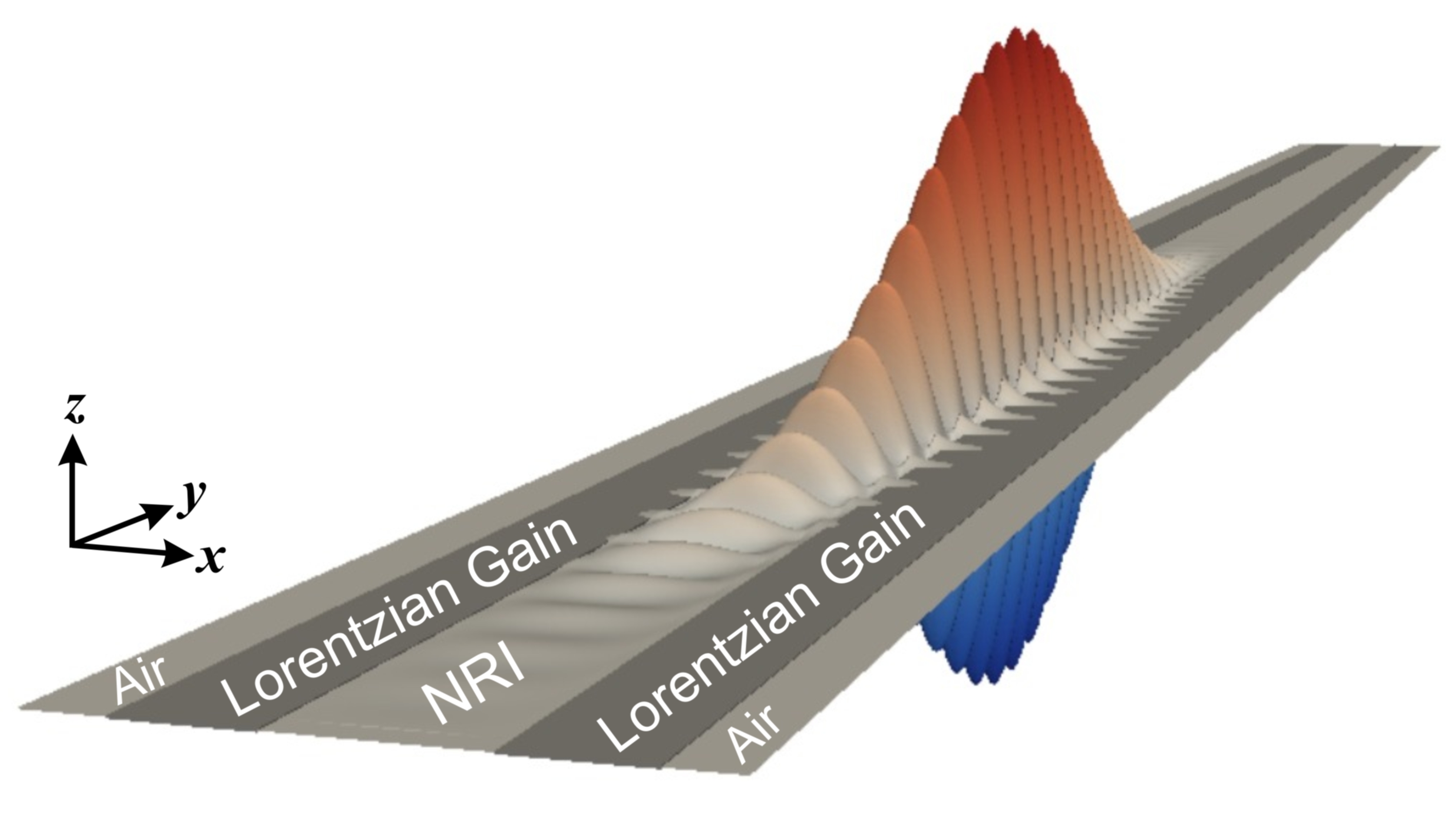
In this Letter, on the basis of analytical calculations and rigorous numerical simulations, we show how the incorporation of thin layers of a gain medium in a passive trapped rainbow heterostructure can compensate the losses while simultaneously preserving the negative effective refractive index of the guided slow light. The specific structure considered is illustrated in Fig. 1. It consists of a NRI core layer bounded symmetrically by two thin gain layers that evanescently feed the supported guided modes Fang06 . The whole structure is embedded in air.
When gain or losses are present in one or more of the layers of a heterostructure the supported guided modes become complex. Apart from the usual complex-wavevector (real-frequency) solutions to the characteristic equation, one may then also retrieve complex-frequency (real-wavevector) solutions Alexander74 ; *Gammon74; *Kovener76; *Archambault09. For instance, it is well-known from prism-coupling to uniform metallic films that fixing the incident light frequency and sweeping the angle of incidence results in the excitation of complex-k surface plasmon polaritons (SPPs) exhibiting back-bending in the ω-k dispersion diagram. By contrast, keeping the incident angle constant and varying the frequency of the incident light gives rise to the excitation of complex-ω SPPs with distinct reflectivity dips and no back-bending Alexander74 ; Kovener76 . The imaginary part of a complex-ω solution relates to the temporal losses experienced by a light pulse Archambault09 .
A numerical framework that is well-suited for the study of these modes is the finite-difference time-domain (FDTD) method Taflove . With this method one can accurately launch the desired negative phase velocity (backward) mode into the waveguide and directly investigate its temporal losses Kirby09 . In our simulations we deploy a modified total-field/scattered-field formulation Taflove , with the excitation plane oriented perpendicularly to the central axis of the heterostructure of Fig. 1, and the amplitudes of the - and - field components along the plane being set to match the transverse profile of the backward TM mode. The central frequency of the injected pulse is fixed to 400 THz ( = 750 nm), the side of the square FDTD cell has a length of = = 3.75 nm and the Courant value is set to 0.7. The width of the core layer is = 0.35 = 262.5 nm, while the width of the gain layers in the cladding is whenever they are incorporated in the heterostructure. We model the passive NRI of the core layer using a broadband Drude response (Engheta, , Chap. 1.3): , with rad/s and rad/s. The frequency response of the permittivity of the gain layer obeys a Lorentzian dispersion: , with = 1.001, = – 0.0053, = rad/s, and = rad/s, resulting in a line-shape that is similar to that produced by, e.g., an electronic transition in a quantum dot Govyadinov07 .
When the losses and gain are relatively small, as those used in the considered NRI heterostructure, the imaginary part of the complex-ω solution is proportional to the imaginary part of the complex-k solution by a factor that is close-to-equal to the group velocity Huang04 . Hence, in this case, one has an additional opportunity (see Fig. 4 later on) to check the accuracy of the obtained numerical results by examing whether such a proportionality is fulfilled. Following the standard theory of active optical waveguides Casey , we assume that the saturation intensity for the gain medium is sufficiently large, leading to a correspondingly large value of the critical gain-length product beyond which gain depletion owing to amplified spontaneous emission (ASE) can become significant MilonniLasers . Operation sufficiently below this limit implies that we are in the linear regime where no gain depletion occurs, and that the effect of ASE on the signal gain may be disregarded, in accordance with analogous studies of active optical structures Casey ; Jiang09 ; *Lu10; Zheludev08 .
To analyically confirm the accuracy of the numerical results we have developed a frequency-domain transfer-matrix method (TMM) capable of identifying both the complex-ω and complex-k modes of the multilayer NRI heterostructure. The method derives the dispersion equation and uses the argument principle method to locate and isolate its zeros either on the complex-ω or the complex-k plane Kwon04 . Suitable conformal mappings are deployed in both cases to unfold the four-sheeted Riemann surfaces associated with the characteristic equations. Upon isolation of a zero, the Newton-Raphson method is used to pinpoint and track its location on the complex plane. The technical details of the overall procedure will be presented elsewhere.
In our analyses we consider the following four cases: (I) neither loss in the NRI core layer ( = 0) nor gain in the cladding layers (the cladding is only air), (II) loss in the NRI core layer but no gain in the cladding, (III) both loss in the NRI region and gain in the cladding strips, and (IV) the NRI core layer is modeled as being lossless and gain is used in the two cladding layers.
In order to validate the causal dynamics of the injected pulse with the FDTD method we created an animation of its propagation along the considered heterostructure Paper2-supplimentary2 . From there one may directly see that first, a single slow-light guided mode is excited and second, the mode experiences an effective refractive index with a negative real part, having antiparallel phase and group velocities.
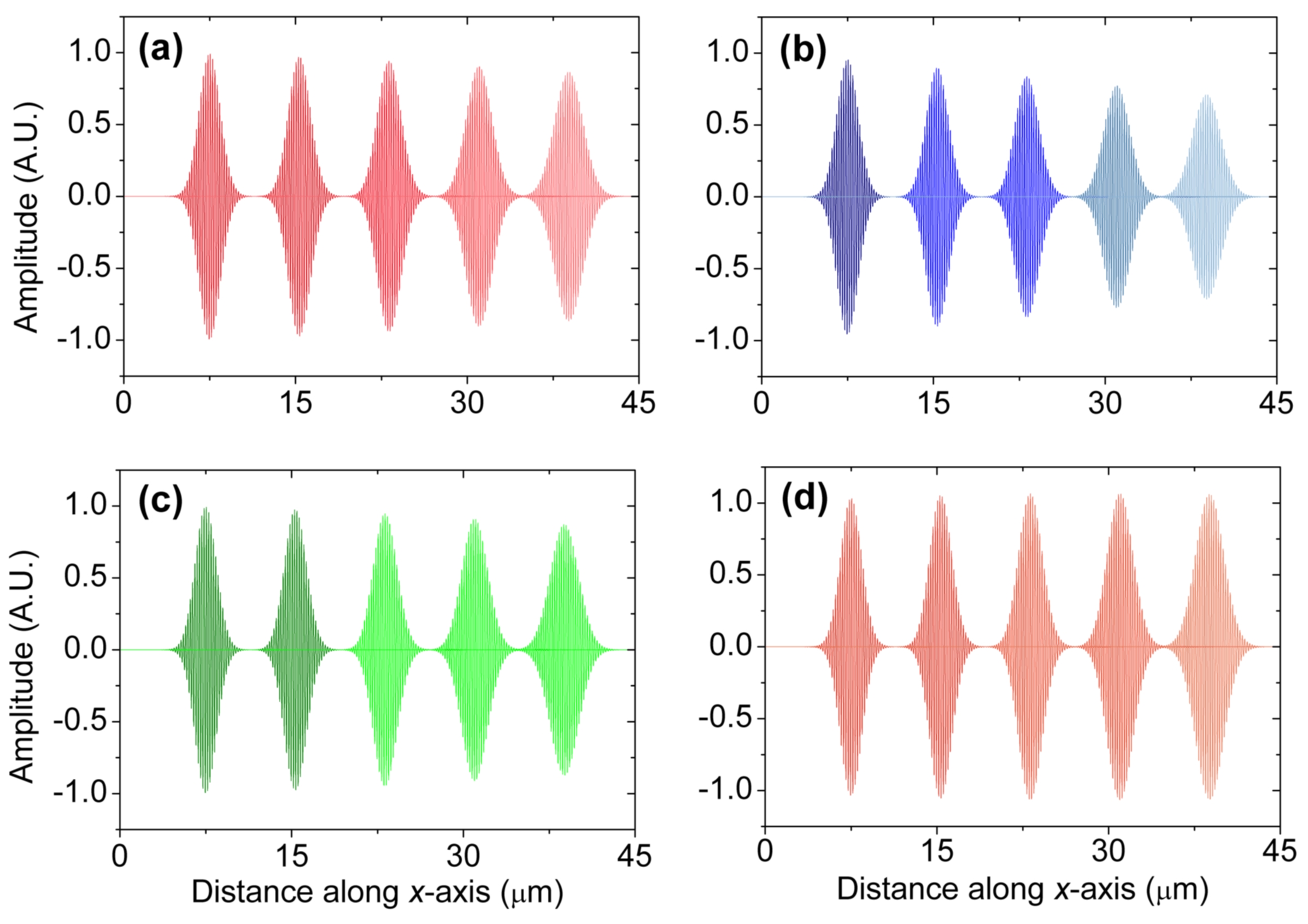
Sucessive snapshots of the Gaussian pulse propagating down the NRI waveguide for cases I-IV are depicted in Fig. 2. We see that for case I (neither loss nor gain) the amplitude of the guided pulse decays with distance [Fig. 2(a)]. This reduction is not a result of the pulse losing energy but arises entirely owing to group-velocity dispersion, which causes the guided slow pulse to broaden, thereby leading to a gradual decay in amplitude. Figure 3 (red solid line and symbols) confirms the fact that energy is conserved, as the absorption coefficient (spatial losses) is zero throughout the frequency spectrum of the pulse. The complex shown in Fig. 3 for all considered cases is extracted by recording the amplitude of the pulse at two fixed points along the central axis of the waveguide over time, and then dividing the Fourier transforms of the two time series Taflove ; Kirby09 . When dissipative loss is introduced into the NRI core (case II) the amplitude of the pulse decreases even further compared to case I [Fig. 2(b)]. Figure 3 (blue solid line and symbols) shows that now Im for all frequencies, as expected.
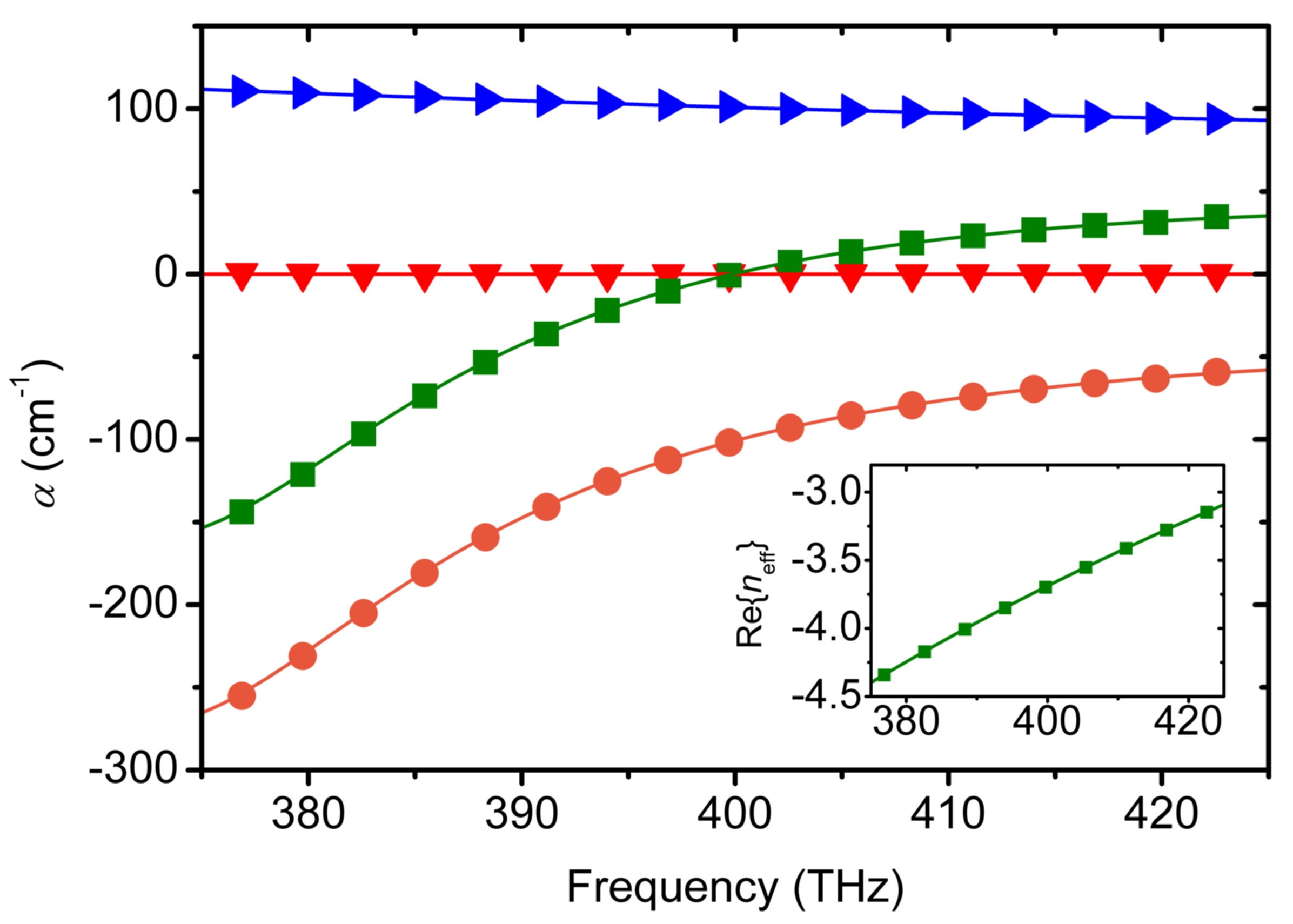
By introducing gain in the cladding layers (case III) we evanescently pump the pulse Fang06 and allow for the compensation of its propagation losses [compare Fig. 2(c) with Fig. 2(a)]. Indeed, Fig. 3 (green solid line and squares) shows that at approximately 400 THz (central frequency of the pulse) the imaginary part of the effective refractive index becomes zero, while for smaller frequencies Im assumes negative values (amplification). Thus, in case III there is a continuous range of frequencies () where we simultaneously have Re (inset in Fig. 3) and Im (green line for THz in Fig. 3). We note that the optogeometric parameters of the heterostructure have been chosen such that a light-pulse experiences almost the same frequency dispersion for all cases, with differences between the various Re (cases I-IV) being indiscernible at the linear scale of the inset in Fig. 3. For all cases presented we find that the parameters retrieved from the FDTD simulations (symbols) are in excellent agreement with those calculated using the TMM (lines).
To further confirm that light amplification is in principle possible in the negative index slow-light regime we “switch off” the losses, while maintaining the gain in the cladding strips. Figure 2(d) shows that in this case (IV) the negative-phase-velocity slow pulse is amplified while propagating along the waveguide. In particular, it is seen that the pulse amplitude at around x = 40 μm exceeds its initial amplitude despite the fact that the pulse has been broadened due to group-velocity dispersion. This conclusion is further confirmed by finding that Im throughout the spectrum of the Gaussian pulse, as shown in Fig. 3 (orange solid line and symbols).
Next, we examine how the spatial and temporal losses (or gain) experienced by both the central frequency of the pulse and the pulse as a whole vary with core thickness (Fig. 4). The complex-ω solutions can be calculated with the FDTD method by recording the spatial variation of the field amplitude along the central axis of the heterostructure at two different time points, and then dividing the spatial Fourier transforms of the two longitudinal spatial profiles. The rate of energy change for the whole wavepacket (total loss or gain) is calculated using the discrete Poynting’s theorem integrated over a spatial region sufficiently wide to contain the pulse.
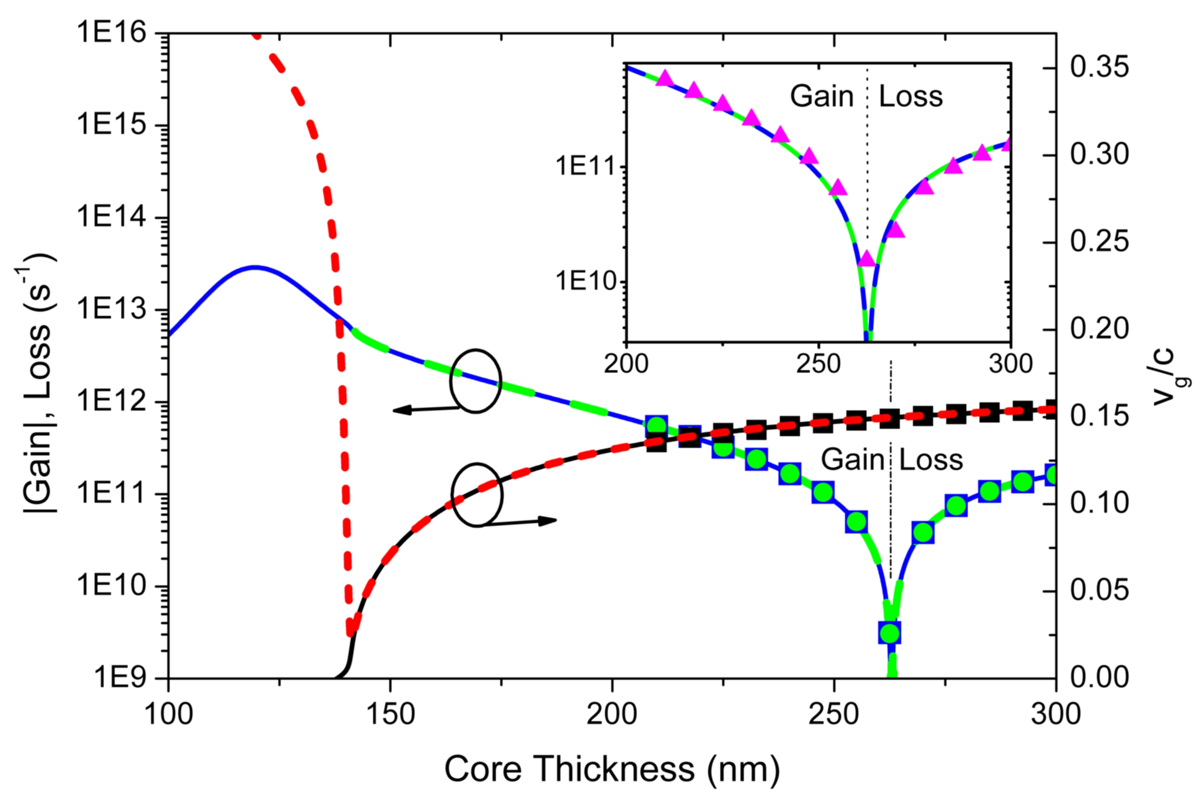
Figure 4 shows that for core thicknesses above 262 nm the central frequency of the pulse experiences loss. For smaller thicknesses, for which the amplitude of the field increases inside the gain region, we find that the gain supplied by the cladding strips overcompensates the loss induced by the core layer. At a core thickness of 262 nm the central frequency experiences neither gain nor loss, while the wavepacket as a whole experiences gain (inset in Fig. 4). In all cases we have verified that Re (data not shown here).
Overall, we find excellent agreement and consistency between five distinct sets of results: the spatial losses/gain (multiplied by the group velocity Huang04 ) for the central frequency as calculated by the FDTD (green dots) and the TMM (green dashed line), the temporal losses/gain for the central frequency as calculated by the FDTD (blue squares) and TMM (blue dashed line), and the temporal losses of the whole wavepacket as calculated by the FDTD method (purple symbols in the inset of Fig. 4). This fact provides further evidence that loss compensation is in principle possible in the slow-light NRI regime.
Finally, we note that for core thicknesses smaller than around 140 nm the group velocity of the complex-k mode characteristically differs from that of the complex-ω mode (red dashed and black solid lines in Fig. 4). As with the case of SPPs in plasmonic films Alexander74 ; Kovener76 , the group velocity of the complex-k solutions exhibits a “back-bending”, never becoming zero, while that associated with the complex-ω solutions may reduce to zero even in the presence of excessive gain (or losses).
In conclusion, by studying in the time- and frequency-domain the complex-ω and complex-k modes in NRI slow-light waveguides with gain in the cladding region, we have shown that it is possible to compensate the dissipative optical losses. This geometry allows for lossless or amplified slow-light propagation in the regime where the real part of the effective refractive index experienced by the guided modes remains negative. We believe that this work could aid the realization of lossless metamaterial waveguides to be used in a wealth of photonic and quantum optics applications.
We gratefully acknowledge financial support provided by the EPSRC and the Royal Academy of Engineering.
References
- (1) P. W. Milonni, Fast Light, Slow Light and Left-Handed Light (Taylor and Francis, New York, 2005)
- (2) Slow Light: Science and Applications, edited by J. B. Khurgin and E. S. Tucker (Taylor and Francis, New York, 2009)
- (3) M. D. Lukin and A. Imamoglu, Nature (London) 413, 273 (2001)
- (4) K. L. Tsakmakidis, A. Boardman, and O. Hess, Nature (London) 450, 397 (2007)
- (5) A. J. Hoffman et al., Nat. Materials 6, 946 (2007)
- (6) R. Singh et al., J. Opt. 12, 015101 (2010)
- (7) K. L. Tsakmakidis, E. I. Kirby, and O. Hess, Proc. SPIE 7612, 76120U (2010)
- (8) Q. Bai et al., Opt. Express 18, 2106 (2010)
- (9) Q. Gan, Z. Fu, Y. Ding, and F. Bartoli, Phys. Rev. Lett. 100 (2008)
- (10) Y. Zhao, P. Belov, and Y. Hao, Phys. Rev. E 75 (2007)
- (11) V. N. Smolyaninova et al., Appl. Phys. Lett. 96, 211121 (2010)
- (12) S. Xiao et al., Nature (London) 466, 735 (2010)
- (13) S. Wuestner et al., Phys. Rev. Lett. 105, 127401 (2010)
- (14) A. Fang, T. Koschny, and C. M. Soukoulis, Phys. Rev. B 82, 121102(R) (2010)
- (15) A. Reza, M. M. Dignam, and S. Hughes, Nature (London) 455, E10 (2008)
- (16) K. L. Tsakmakidis, A. D. Boardman, and O. Hess, Nature (London) 455, E11 (2008)
- (17) See EPAPS Document No. 1 for a QuickTime movie illustrating an example (case IV) of the propagation of the excited negative-phase-velocity slow-light mode along the waveguide heterostructure of Fig. 1. Similar dynamics (negative phase velocity) are seen for cases I-III.
- (18) A. W. Fang et al., Opt. Express 14, 9203 (2006)
- (19) R. W. Alexander, G. S. Kovener, and R. J. Bell, Phys. Rev. Lett. 32, 154 (1974)
- (20) R. W. Gammon and E. D. Palik, J. Opt. Soc. Am. 64, 350 (1974)
- (21) G. S. Kovener, J. R W Alexander, and R. J. Bell, Phys. Rev. B 14, 1458 (1976)
- (22) A. Archambault et al., Phys. Rev. B 79, 195414 (2009)
- (23) Computational Electrodynamics: The Finite-Difference Time-Domain Method, 3rd ed., edited by A. Taflove and S. C. Hagness (Artech House, 2005)
- (24) E. I. Kirby et al., J. Opt. A: Pure Appl. Opt. 11, 114027 (2009)
- (25) Metamaterials: Physics and Engineering Explorations, edited by N. Engheta and R. W. Ziolkowski (Wiley-IEEE Press, New Jersey, 2006)
- (26) A. A. Govyadinov, V. A. Podolskiy, and M. A. Noginov, Appl. Phys. Lett. 91, 191103 (2007)
- (27) K. C. Huang et al., Phys. Rev. B 69, 195111 (2004)
- (28) H. C. Casey and M. B. Panish, Heterostructure Lasers Part A: Fundamental Principles (Academic Press, New York, 1978)
- (29) P. W. Milonni and J. H. Eberly, Lasers (Wiley, 1988)
- (30) T. Jiang and Y. Feng, Opt. Lett. 34, 3869 (2009)
- (31) W. T. Lu et al., Appl. Phys. Lett. 96, 211112 (2010)
- (32) N. Zheludev, S. Prosvirnin, N. Papasimakis, and V. Fedotov, Nat. Photonics 2, 351 (2008)
- (33) M.-S. Kwon and S.-Y. Shin, Opt. Commun. 233, 119 (2004)