Interaction of Spherical Colloidal Particles in Nematic Media with Degenerate Planar Anchoring
Mohammad Reza Mozaffaria, Mehrtash Babadi, Jun-ichi Fukuda, and Mohammad Reza Ejtehadi
The interaction between two spherical colloidal particles with degenerate planar anchoring in a nematic media is studied by numerically minimizing the bulk Landau-de Gennes and surface energy using a finite element method. We find that the energy achieves its global minimum when the particles are in close contact and making an angle with respect to the bulk nematic director, in agreement with the experiments. Although the quadrupolar structure of the director field is preserved in the majority of configurations, we show that for smaller orientation angles and at smaller inter-particle separations, the axial symmetry of the topological defect-pairs is continuously broken, resulting in the emergence of an attractive interaction.
1 Introduction
Studying the behavior of colloidal particles in anisotropic fluids with long-range orientational ordering, such as nematic liquid crystals, has attracted a great attention in soft condensed matter physics 1, 2, 3, 4, 5, 6. The orientation order parameter of the fluid (e.g. director of nematic liquid crystal) is distorted from its uniform orientation in the bulk due to anchoring to the surface of the colloidal particles. These elastic distortions create topological defects around the particles 7 and induce anisotropic long and short range interactions between the particles 8, 9.
Depending on the colloidal material and its coating, the surrounding fluid may have a normal orientation (normal or homeotropic anchoring), or parallel orientation (planar anchoring) with respect to the colloidal surfaces. For normal anchoring, the orientation of the fluid is locally and uniquely determined on the colloidal surfaces. For planar anchoring, the orientation of the fluid is degenerate on the colloidal surfaces and is determined by the global structure of the fluid. However, the director field in the surface of the particles is affected by environment for any finite anchoring, such a freedom makes the theoretical investigations more complicated for planar anchoring.
In case of a single colloidal particle, the particle-defect pair induces a dipolar or a quadrupolar long-range elastic distortion field 10, 11 depending on the anchoring type. The long-range dipolar structure results from a satellite point defect, when the size of the particle is large compared to the coherence length of the nematic fluid and the anchoring is normal 9, 7. The quadrupolar configuration appears in both normal and planar anchorings. In the normal case, a disclination ring (saturn ring) encircles the particle, when the size of the particle is small or the strength of anchoring is weak 8, 7. In planar anchoring, the elastic distortions form two point defects (boojums) at the poles of the particles, aligned along the nematic direction 8, 7.
The more physically interesting configurations are achieved when there are many colloidal particles present in the medium. For large separations of particles, the defects around of each of the particles is independent of that of the other particles, and (anisotropic) interaction potential between them is determined by the long-range orientational field of the fluid. In this regime, and in case of two particles separated by a distance , the effective interaction potential between them is proportional to or for dipolar or quadrupolar defect configurations, respectively 1, 8, 7, 3. When the particles approach each other, the defect structures are distorted and the interactions deviate from the far-field dipolar-dipolar or quadrupolar-quadrupolar interactions 12, 13, 14, 15, 16, 17, 18.
Experimentally, the colloidal interactions in nematic liquid crystals are studied using optical 4 or magneto-optical tweezers 19, 20. The medium-induced interactions play an essential role in the formation of chain 4 or crystal 2, 21, 22 suspensions of the colloids (or droplets) in nematic liquid crystals.
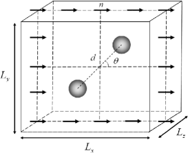
Smalyukh et al. 4 have measured the angular and the radial components of the force between two particles with planar anchoring in a nematic liquid crystal as a function of the inter-particle separation , the angle between the bulk nematic director and the vector connecting the particles, (see Fig. 1). They observe deviation from the far-field theoretical quadrupole-quadrupole interaction 8 when the objects are in the close-contact regime. They also find that the equilibrium configuration corresponds to a very small separation of particles, , and .
In this paper, we study the fluid-induced interaction between two spherical colloidal particles of radius by numerically minimizing the sum of elastic Landau-de Gennes free energy of the bulk fluid 23 and the degenerate planar anchoring surface energy introduced by Fournier et al 24. In particular, we are interested in the regime of strong anchoring and large particles ( large compared to the coherence length of the fluid, ). Our main goal is to study the close-contact configurations for which no theoretical work has been done to our knowledge, though interesting physics is expected to emerge due to the strong interaction of the topological defects. We also aim to explain the experimentally observed angle of at equilibrium.
2 The Model
The geometry of the studied system is schematically illustrated in Fig. 1. We consider two identical spherical colloidal particles with radius immersed in a 3D nematic cell. The nematic director is aligned along -axis at the boundaries of the cell. We scale all the lengths with respect to the radius of the particles. The dimensions of the cell is , and . The centers of the particles are confined to the plane and are separated by a center-to-center distance . The line joining the center of the particles makes an angle with -axis. The dimensions of the cell are chosen in a way to ensure that in all of the studied configurations, the distance between the boundaries and the particles is much larger than the coherence length and big enough so that the nematic director distribution is not affected by the boundaries. The free energy of the system can be written as:
| (1) |
where is bulk nematic fluid free energy , is the surface energy and is the Van der Waals colloid-colloid interaction. The free energy functionals will be described in detail in the following sections.
In realistic situations, the only appreciable effect of Van der Waals colloid-colloid interactions is to provide a short-range repulsion between the colloidal particles. Such effects become relevant only in the regime where the separation of the colloid surfaces approaches the atomic length-scales. In this study, we confine ourselves to the regime where the surface separations are larger than the nematic coherence length, i.e. . We note that the surface separations can chosen to be appreciably smaller than the size of the particles in this regime. Therefore, due to the separation of scales in this regime, we ignore the Van der Waals interaction between the colloids in this study.
2.1 The Nematic Order Parameter
The nematic fluid is described by a local, , traceless and symmetric tensor order parameter, , which can be specified by five independent components,
| (2) |
where . The scalar order parameter, , and the director orientation, , are locally obtained by the largest eigenvalue of the tensor order parameter, , and its corresponding eigenvector, respectively. We note that working with a tensor order parameter and expanding the free energy in its terms allows the formation of biaxial order, which is a necessary ingredient for a realistic description of topological defects and their interactions.
2.2 The Bulk Free Energy
The bulk free energy of the nematic fluid is described well by the Landau-de Gennes model 23, in which the free energy functional is expanded in powers of the tensor order parameter and its spatial derivatives:
| (3) |
where the indices refer to Cartesian coordinates, the summation over repeated indices is assumed and denotes the volume occupied by the nematic liquid crystal. The first three terms are the Landau-de Gennes free energy which describe the bulk isotropic-nematic (IN) transition. The coefficients , , and are the material-dependent parameters.
The derivative terms are the contribution of the elastic free energy in the nematic phase. The nematic elastic constants, and , are related to the Frank elastic constants by and . In this study we restrict ourselves to one-elastic constant approximation that means all the Frank elastic constants should be equivalent which leads to .
To simplify calculations, we rescale the tensor order parameter as , such that , where . As a consequence, the dimensionless free energy becomes
| (4) |
where , is effective dimensionless temperature, is the nematic coherence length 25, 26. In these dimensionless units, the fluid undergoes a first-order isotropic-nematic transition at . The isotropic phase becomes unstable for . The scalar nematic order parameter in bulk is given by . Throughout this paper, the quantities appearing with a hat are rescaled with respect to the the radius of the particles, e.g. , and . Following the related previous studies 25, 26, 15, the dimensionless temperature and length scales were set to and respectively. This choice of parameters closely match the parameters of the widely used liquid crystal mesogen 5CB and results in formation of stable topological defects 25, 26.
2.3 The Surface Free Energy
As mentioned in the introduction, the preferred anchoring can be modeled with much more ease 27, 28 compared to the planar degenerate anchoring due to uniqueness of the orientation of nematic fluid in the vicinity of the colloidal surfaces.
Fournier et al. 24 have recently introduced a two-parameter surface energy functional that is bounded from below and assumes its minimum in the manifold of degenerate planar configurations. The surface energy consists of two terms, controlling the planar anchoring and fixing the scalar order parameter on the surface. Since we expect the formation surface topological (e.g. two surface defects of charge in case of a single colloid), we relax the second constraint like previous studies 20, resulting in the following single parameter surface energy functional:
| (5) |
where , is the projection of onto the tangent plane of the surface, and is the normal to the surface. is positive and controls the stiffness of anchoring. The surface energy can be written in dimensionless variables:
| (6) |
where , , and . We chose , which describes strong planar anchoring to the surface once we take the bulk free energy parameters into account.
3 Numerical Minimization of the Free Energy
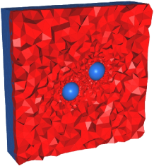
We adopt a finite element method (FEM) approach to minimize the free energy functional described in the preceding sections. The nematic cell was decomposed into tetrahedral elements by using the automatic mesh generator Gmsh 29. In order to capture a more accurate representation of the curved surfaces and to provide increased numerical accuracy near the topological defects which are expected to be formed on or in the vicinity of the surfaces, a finer mesh size of was used near the shperical boundaries. We note that since the nematic coherence length is , the physics of elastic deformations can be properly captured in the used mesh. The mesh size was increased to away from the particles in order to reduce the computational cost (see Fig. 2). The tensor order parameter was linearly interpolated within each of elements in the evaluation of the free energy integrals. We note that linear interpolation is the simplest scheme that preserves the properties of as an order tensor. For each configuration of the particles, the total dimensionless free energy was minimized using a conjugate gradient (CG) method 30, yielding the Effective Potential Energy (EPE) . In order to accelerate the minimization procedure for any given (, ), we used the relaxed director profile from the closest preceding configuration as the initial guess. The configuration space of the particles was scanned in the range and in steps of and respectively. For larger separations, , we scan with larger steps of . For each configuration, the minimization procedure was stopped when the relative free energy improvements dropped below . We present and discuss the results in the next section.
4 Results and Discussion
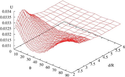
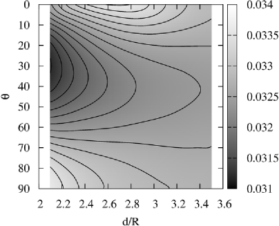
Figure 3 shows the full equilibrium free energy landscape of the system. The smooth contour plot of the free energy landscape is shown in Fig.4 for better clarity. The normal to the contour lines specify the direction of the net force between the colloidal particles. The effective potential energy of the system of two colloids is also shown in Fig. 5 as a function of the particle separation , for four different orientations. The figure shows that for , the particles repel each other in the whole range of inter-particle separations, while they attract each other at and , with a stronger attraction in the later case. This uniform attractive or repulsive behavior is destroyed for configurations with smaller angles. In particular, in the case of , the particles attract each other in the close-contact regime, , while they repel each other for the larger separations. We will show later that this peculiar behavior is associated to the spontaneous broken axial symmetry of the defect pairs.
In order to analyze the distance dependence of the effective potential, we have fitted a two-parameter function to the plots of Fig. 5. The fits are shown in Fig. 6 and correspond to exponents and for and respectively. It is noticed that exponents are slightly larger in magnitude in comparison to the weak anchoring analytical analysis 8, . The exponent is for , which describes a deformation field of longer range in contrast to the weak anchoring theory. Finally, in the case , the exponent is in agreement with the analytical prediction, .
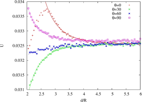
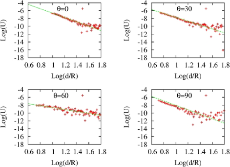
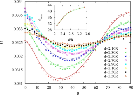
Fig. 7 shows the effective potential energy as a function of angle for fixed particle-particle separations (, , , , , , and ). It is noticed that each of the plots has a unique global minimum. Moreover, the free energy minimum, as well the orientation angle at which the minimum is achieved (), decreases monotonously as the particles approach each other. This behavior is shown clearly in the inset plot of Fig. 7. Extrapolating to the limit , we find that the global minimum of the free energy is achieved for . This result is consistent with the experimental results of Poulin et al. 7, Smaylukh et al. 4 and Kotar et al. 19, who find the equilibrium angle to be .
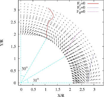
The vector field of the net force between the particles can be calculated by taking the gradient of the effective potential energy. The net force field is shown in Fig. 8 and the configurations at which the radial () and tangential () components of the net force vanishes are indicated. It is easily noticed that the force field drives the system towards the configuration of minimum free energy, i.e. and . The radial component of the net force is positive for and thus, the force is repulsive. The angle at which the radial component of net force changes sign depends on the inter-particle separation and varies in the range for the investigated configurations. Repulsive interaction is expected to show up when in quadrupolar approximation 4. We associate this slight discrepancy to deviations from the quadrupolar approximation.
As it was mentioned earlier in this section, the inter-particle force exhibits a non-monotonous behavior as a function of inter-particle separation for small angles (). This behavior can be seen in Figs. 5, 4 and 8. In particular, for , the net force is repulsive for large separations, while it becomes attractive for . To our knowledge, this peculiar behavior has not been studied theoretically elsewhere.
Moreover, its experimental observation requires measurement the interaction force in separations smaller than those reported in the experimental paper by Smalyukh et al. 4, 31. We note that precise experimental measurement of this phenomenon can be carried out by fixing the orientation of the colloidal particles by using line optical tweezers 32.
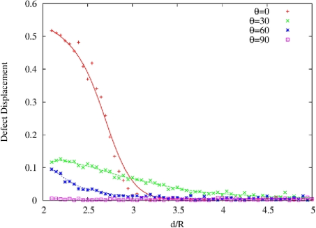
In order to gain insight into this phenomenon, we study the configuration of the topological defects at different inter-particle separations, as shown in Fig. 9. When the particles are well separated (), the boojum defects are aligned on the -axis and the defect-particle pairs have a quadrupolar symmetry for each of the colloidal particles. The repulsion in this regime is thus associated to the head-to-head interaction of defects of equal charge (Fig. 9a). When particles approach each other, the continuous symmetry of the defect pairs is continuously broken due to the strong repulsion between the approaching boojums, driving them away from the axis of symmetry (Fig. 9b-c). The nematic director profile on the front and back of the colloidal particles is shown in Fig. 10a and 10b respectively, as seen along the -axis. It is noticed that the approaching pair of boojums are driven away from the -axis (Fig. 10a), while the boojums on the back of the particles remain on the -axis. The displacement of the approaching pair of boojums induces an attraction between the colloidal particles due to the energetic tendency to reduce the volume of the distorted region between the particles.
At larger angles (), the axial symmetry of the defect-pair on each of the particles is almost preserved in the whole range of inter-particle separations (see Fig. 11 and Fig. 12). Therefore, the monotonous attractive or repulsive interaction at larger angles can be explained by merely taking into account the quadrupolar deformation field of each of the particles 8.
We finally remark that although the calculations were carried out for a specific choice of bulk and surface energy parameters, we expect our results to be insensitive to variations in the parameters as long as they describe the same (, and strong anchoring).
| a | 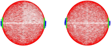 |
|---|---|
| b | 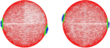 |
| c | 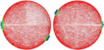 |
| a | 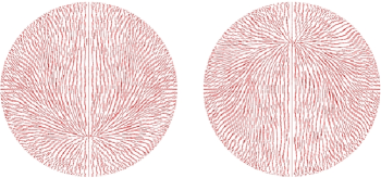 |
|---|---|
| b | 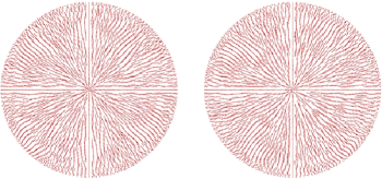 |
| a | 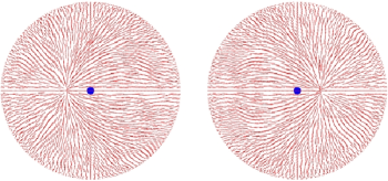 |
|---|---|
| b | 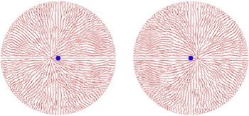 |
| c | 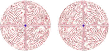 |
| d | 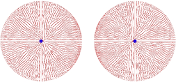 |
5 Conclusions
In this paper, we studied the interaction of two spherical colloidal particles with degenerate planar anchoring in a nematic media by numerically minimizing the Landau-de Gennes 23 bulk and Fournier 24 surface energy using a finite element method. Our choice of parameters belong to the regime of large particles (in comparison to the nematic coherence length) and strong surface anchoring. We obtained the nematic-induced effective potential energy of the system for different inter-particle separations and orientations with respect to the bulk nematic director.
By studying the free energy landscape of the system, we found that the system assumes its unique global minimum of energy when the particles are in close contact and are oriented at an angle with respect to the bulk nematic director. Our results are in a very close agreement with the experimental results in Ref. 4, . To the best of our knowledge, we have provided the first clear theoretical explanation of these experimental findings.
Our results suggest that for large inter-particle separations, the quadrupolar structure of the defect-pair on each of the particles is essentially preserved, resulting in a monotonous attractive or repulsive inter-particle net force, depending on the orientation angle. However, for smaller orientation angles () and at smaller inter-particle separations, the axial symmetry of the defect-pairs is continuously broken, resulting in the emergence of an attractive interaction due to the tendency of the system to reduce the volume of distorted fluid. This very unexpected attraction, in very short distances, has not been reported before and may be of interest to be explored experimentally too.
The Finite Element method, used in this study, simply can be
extended to more complicated geometries. Inter-particles interaction
for nonspherical colloids with planar
anchoring 33 and also many-body
interactions between the colloids in colloidal
aggregations 34, 35
are in direction of our future studies.
Aknowledgement:
We would like to thank Seyyed Mehdi Fazeli, Maryam Saadatmand, Ivan Smalyukh and Yasuyuki Kimura for their valuable comments and discussions. MRE acknowledges the Center of Excellence in Complex Systems and Condensed Matter (CSCM) for partial support.
References
- Poulin et al. 1997 P. Poulin, H. Stark, T. C. Lubensky and D. A. Weitz, Science, 1997, 275, 1770.
- Nazarenko et al. 2001 V. G. Nazarenko, A. B. Nych and B. I. Lev, Phys. Rev. Lett., 2001, 87, 075504.
- Yada et al. 2004 M. Yada, J. Yamamoto and H. Yokoyama, Phys. Rev. Lett., 2004, 92, 185501.
- Smalyukh et al. 2005 I. I. Smalyukh, O. D. Lavrentovich, A. N. Kuzmin, A. V. Kachynski and P. N. Prasad, Phys. Rev. Lett., 2005, 95, 157801.
- Musevic et al. 2006 I. Musevic, M. Skarabot, U. Tkalec, M. Ravnik and S. Zumer, Science, 2006, 313, 954.
- Fukuda 2009 J. Fukuda, J. Phys. Soc. Japan, 2009, 78, 041003.
- Poulin and Weitz 1998 P. Poulin and D. A. Weitz, Phys. Rev. E, 1998, 57, 626.
- Ruhwandl and Terentjev 1997 R. W. Ruhwandl and E. M. Terentjev, Phys. Rev. E, 1997, 55, 2958.
- Lubensky et al. 1998 T. C. Lubensky, D. Pettey, N. Currier and H. Stark, Phys. Rev. E, 1998, 57, 610.
- Stark 2001 H. Stark, Physics Reports, 2001, 351, 387.
- Lev et al. 2002 B. I. Lev, S. B. Chernyshuk, P. M. Tomchuk and H. Yokoyama, Phys. Rev. E, 2002, 65, 021709.
- Guzman et al. 2003 O. Guzman, E. B. Kim, S. Grollau, N. L. Abbott and J. J. de Pablo, Phys. Rev. Lett., 2003, 91, 235507.
- Andrienko et al. 2003 D. Andrienko, M. Tasinkevych, P. Patrício, M. P. Allen and M. M. T. da Gama, Phys. Rev. E, 2003, 68, 051702.
- Silvestre et al. 2004 N. M. Silvestre, P. Patrício, M. Tasinkevych, D. Andrienko and M. M. T. da Gama, Journal of Physics: Condensed Matter, 2004, 16, S1921.
- Ravnik et al. 2007 M. Ravnik, M. Skarabot, S. Zumer, U. Tkalec, P. I., D. Babic, N. Osterman and I. Musevic, Phys. Rev. Lett., 2007, 99, 247801.
- Fernandez-Nieves et al. 2007 A. Fernandez-Nieves, V. Vitelli, A. S. Utada, D. R. Link, M. Marquez, D. R. Nelson and D. A. Weitz, Phys. Rev. Lett., 2007, 99, 157801.
- Fukuda and Yokoyama 2005 J. Fukuda and H. Yokoyama, Phys. Rev. Lett., 2005, 94, 148301.
- Takahashi et al. 2008 K. Takahashi, M. Ichikawa and Y. Kimura, Phys. Rev. E, 2008, 77, 020703.
- Kotar et al. 2006 J. Kotar, M. Vilfan, N. Osterman, D. Babic, M. Copic and I. Poberaj, Physical Review Letters, 2006, 96, 207801.
- Vilfan et al. 2008 M. Vilfan, N. Osterman, M. Copic, M. Ravnik, S. Zumer, J. Kotar, D. Babic and I. Poberaj, Phys. Rev. Lett., 2008, 101, 237801.
- Nych et al. 2007 A. B. Nych, U. M. Ognysta, V. M. Pergamenshchik, B. I. Lev, V. G. Nazarenko, I. Musevic, M. Skarabot and O. D. Lavrentovich, Phys. Rev. Lett., 2007, 98, 057801.
- Smalyukh et al. 2004 I. I. Smalyukh, S. Chernyshuk, B. I. Lev, A. B. Nych, U. Ognysta, V. G. Nazarenko and O. D. Lavrentovich, Phys. Rev. Lett., 2004, 93, 117801.
- de Gennes and Prost 1995 P. G. de Gennes and J. Prost, The physics of liquid crystal, Oxfor university press, 1995.
- Fournier and Galatola 2005 J. B. Fournier and P. Galatola, Europhys. Lett., 2005, 72, 403.
- Fukuda et al. 2004 J.-i. Fukuda, H. Stark, M. Yoneya and H. Yokoyama, Phys. Rev. E, 2004, 69, 041706.
- Fukuda et al. 2005 J. Fukuda, H. Yokoyama, M. Yoneya and H. Stark, Mol. Cryst. Liq. Cryst, 2005, 435, 723.
- Rapini and Popoular 1969 A. Rapini and M. Popoular, J. Phys. (France), 1969, 30, 54.
- Nobili and Durand 1992 M. Nobili and G. Durand, Phys. Rev. A, 1992, 46, R6174.
- 29 C. Geuzaine and J.-F. Remacle, Gmsh: a three-dimensional finite element mesh generator with built-in pre- and post-processing facilities.
- Press et al. 1992 W. H. Press, S. A. Teukolsky, W. T. Vetterling and B. P. Flannery, Numerical Recipes, Cambridge University Press, 2nd edn, 1992.
- 31 Upon the completion of this work, it was brought to our attention in a private communication with Ivan Smalyukh that they had observed displacement of the topological defects in their experiments.
- 32 Private communications with Yasuyuki Kimura.
- Lapointe et al. 2009 C. P. Lapointe, T. G. Mason and I. I. Smalyukh, Science, 2009, 326, 1083.
- Tasinkevych and Andrienko 2006 M. Tasinkevych and D. Andrienko, Eur. Phys. J. E, 2006, 10, 10065.
- Araki and Tanaka 2006 T. Araki and H. Tanaka, Phys. Rev. Lett., 2006, 97, 127801.