Broad-band coherent backscattering spectroscopy of the interplay between order and disorder in 3D opal photonic crystals.
Abstract
We present an investigation of coherent backscattering of light that is multiple scattered by a photonic crystal by using a broad-band technique. The results significantly extend on previous backscattering measurements on photonic crystals by simultaneously accessing a large frequency and angular range. Backscatter cones around the stop gap are successfully modelled with diffusion theory for a random medium. Strong variations of the apparent mean free path and the cone enhancement are observed around the stop band. The variations of the mean free path are described by a semi-empirical three-gap model including band structure effects on the internal reflection and penetration depth. A good match between theory and experiment is obtained without the need of additional contributions of group velocity or density of states. We argue that the cone enhancement reveals additional information on directional transport properties that are otherwise averaged out in diffuse multiple scattering.
pacs:
78.67.bf, 42.25.Fx, 73.20.mfI Introduction
Photonic crystals are ordered nanostructures with a periodicity on the scale of the optical wavelength. The perfect periodic ordering gives rise to a photonic band structure and properties such as slow light, negative refraction, and photonic band gaps.Joannopoulos Photonic crystals are of importance for their potential in controlling the transport and emission of light at the nanoscale.Yab87 ; John87 Apart from the properties of perfect photonic crystals, such as a 3D photonic bandgap, the possibility of combining band structure with controlled random multiple scattering has raised considerable interest. Macroscopic photonic crystals can be assembled bottom-up using colloidal suspensions, or top-down using lithographic techniques. All crystals have some degree of intrinsic disorder due to polydispersity of the building blocks or imperfections in fabrication.Li2000 ; Vlasov2000 ; KoenderinkPLA ; HuangPRL01 ; Astratov2002 ; Noda2002 ; KoenderinkPRL03 ; Allard2004 ; Rengarajan2005 In order to realize random multiple scattering without relying on intrinsic disorder, another route has been explored to intentionally design disorder in three-dimensional photonic crystals of very high quality.Garcia09 The role of disorder has recently been investigated in photonic crystal waveguides.Kuipers08 ; Topolancik07 ; Lodahl10
The presence of disorder results in diffusive scattering of light and a concomitant disappearance of the photonic band structure. However, theoretical and experimental studies indicate that an intermediate regime exists, where photonic band structure is preserved locally but medium-range disorder disrupts ballistic transportJohn87 ; KoenderinkPRL03 ; Kuipers08 ; Toninelli08 ; Erementchouk09 ; Garcia09 . This intermediate scattering regime is reached when the scattering mean free path exceeds the Bragg lengthremark1 but is smaller than the sample size : . As was pointed out by Sajeev John, the modified density of states associated with the photonic bands near a 3D photonic band gap may result in large corrections to the diffuse transport, as is known for completely random systems.John87 Recently it has been argued that the scattering mean free path in opals with designed disorder yield contributions from both the local density of states and group velocity.Garcia09 Ultimately, the photonic crystal could facilitate the complete breakdown of light diffusion known as Anderson localization. Indeed, indications of Anderson localization have been observed in recent studies on one-dimensional photonic crystal waveguidesTopolancik07 ; Lodahl10 and nonlinear lattices Segev07 . Despite recent experimental effortsToninelli08 , this regime has not yet been observed in a three dimensional photonic crystal.
Effects of multiple light scattering in photonic crystals have been studied before using a variety of reflection and transmission measurements, including coherent backscattering of light [Fig. 1(a)]. Coherent backscattering (CBS) is a multiple scattering phenomenon caused by the constructive interference of time-reversed light paths in the medium in a cone around the backscattering direction. Coherent backscattering has been used to investigate multiple scattering of photonic crystals at a few discrete wavelengths.KoenderinkPLA ; HuangPRL01 ; pursiainen07 Recently the first broad-band investigations of opal photonic crystals around the stop band have been reported.Baumberg09 Modifications of CBS cones around the photonic stop bands have been observed which were attributed to two contributions related to the modification of the diffuse source by Bragg reflection, and to variations of the internal reflection conditions at the escape angle of the diffuse light, as shown schematically in Fig. 1(b). Both effects can significantly affect the path length distribution for multiple scattering.
Here, we present experiments demonstrating the effect of the photonic band structure on diffuse light scattering over a wide spectral and angular range in polystyrene opals. We employ a broad-band coherent backscattering technique using a supercontinuum white-light source.muskensOE08 The technique has been used successfully to investigate strongly photonic random media, i.e. TiO2 powder and porous GaP, and to characterize resonant light trapping by semiconductor nanowires.muskensNL09 Compared to earlier studies on photonic crystals KoenderinkPLA ; HuangPRL01 ; pursiainen07 ; Baumberg09 , we achieve a more detailed characterization of CBS as a function of both angle of incidence and wavelength. This investigation over an extensive range of angles and frequencies allows us to compare the results with semi-empirical model calculations to verify earlier predictions.KoenderinkPLA
II Experimental methods
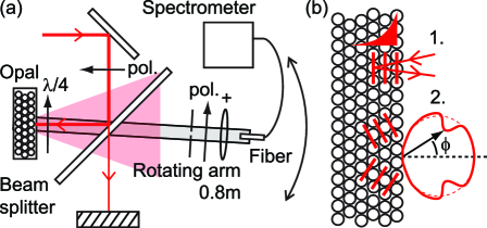
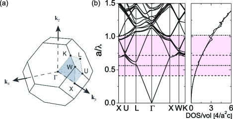
Coherent backscattering spectra were obtained over a wide spectral range in the visible and near-infrared using a supercontinuum white-light backscattering setup described previously in Ref. muskensOE08, . The angular resolution was improved to 0.8 mrad full width at half maximum, in order to resolve the narrow CBS cones of photonic crystals.KoenderinkPLA Small-angle coherent backscattering measurements were obtained in a beamsplitter configuration as shown in Fig. 1(a). Circular polarization channels were selected using achromatic polarizers and a quarter wave plate directly in front of the sample, with the purpose of reducing the contribution of single scattering in the CBS enhancement factor. The opals used in this study were obtained by sedimentation of polystyrene spheres (Duke Scientific, polydispersity 2%) in 0.3 mm thick, 3 mm wide flat glass capillaries (Vitro Dynamics). We used two opals composed of spheres of radii 130 nm and 180 nm, which were grown from a suspension in water using a centrifuge.Vos96 ; Vos97 After crystallization the water was slowly evaporated from the capillaries to produce polycrystalline opals of several millimeters in length. The polystyrene opal is an fcc-crystal with the [111] crystallographic direction (corresponding to L) oriented perpendicular to its surface, as was demonstrated by small-angle x-ray scattering.Vos97 The corresponding Wigner-Seitz cell is shown in Fig. 2(a), while Fig. 2(b) shows the calculated band structure and density of states. In our experiments we investigate the behavior around the stopgap at L, which is located at angle of incidence and has a bandwidth of 6% as predicted by band structure calculations and measured in many reports on opals elsewhere.Vos96 ; Romanov01 ; Galisteo2003 ; Vos01 ; Rengarajan2005 By tilting the sample, we gain access to directions away from the L-gap corresponding to LK, LU, and LW in the band diagram. In the experiments we average over many crystalline regions with random orientations in the (111) plane, and the crystal is spun around its L-axis to average individual speckle. Therefore all directions in the (111) plane will contribute to our experimental results. Since the LK and LU directions are very similar, we focus on the LU and LW bands in the interpretation of our results. Also shown in Fig. 2(b) is the photonic density of states (DOS) (line), compared to that of the homogeneous effective medium (dashed line). Clearly, density of states variations amount to only several percent for opal photonic crystals.Li01 ; Nikolaev08
.
III Results
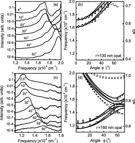
Specular reflectivity measurements were collected for different angles of incidence . Resulting spectra are shown in Fig. 3(a) and (c) for the nm and nm opals, respectively. For both opals a clear dispersion is observed of the stop band, which is centered at 16800 cm-1 for the nm opal and at 12200 cm-1 for the nm opal at near-perpendicular incidence. The frequencies of the half-maximum band edges are shown in Figs. 3(b) and (d) together with band structure calculations, where the lattice constant was adjusted to match the experimental stop band position at . This results in the dimensionless scaled units as shown in the right axes of Fig. 3(b) and (d), and values of the lattice constant of 362 nm and 510 nm, respectively. These values are in good accord with expected values based on the sphere radii using . The experimental dispersion of the stop band matches well the expected behavior for an fcc opal. The full width at half maximum of the reflection peaks of is in excellent agreement with the photonic interaction strength defined as the relative frequency width of the stop gap at the L-point predicted by band structure calculations. In addition, higher order bands approach the stop band at angles around 60∘, resulting in a more complex behavior of the reflected intensityVanDiel2000 ; Romanov01 ; Lopez2004 ; Pavarini2005 , as is observed for the nm sample. Given the spectral range covered by our experimental setup, a set of samples is needed to span nearly a factor three in frequency () that ranges from well below the first order L-gap to the range of second order gaps that are the precursors of the inverse opal band gaps.
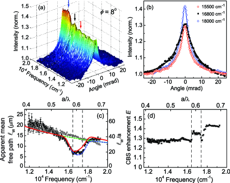
Coherent backscattering spectra were measured for the nm opal for various angles of incidence . A typical CBS spectrum taken at is shown in Fig. 4(a). The CBS spectrum shows a pronounced structure around 16800 cm-1, corresponding to the center frequency of the stop gap. The arrows indicate frequencies below, inside, and above the stop gap, for which cross-sections are shown in Fig 4(b). We note that the height of the CBS cones is not at all related to the peak of the reflectivity in Fig. 3(a). The traces show the typical CBS lineshape, which can be fitted to a model of random light scattering [lines in Fig 4(b)]. We employed a finite slab model analogous to Ref. Mark88, , where the slab thickness was fixed for the full data set. The residuals of all fits are less than 5%, illustrating a very good match. This agreement indicates that the diffusion Green functions are sufficient to calculate the path length distribution underlying the CBS cones, without requiring the addition of photonic band structure effects. The validity of the random scattering model is consistent with earlier experiments.KoenderinkPLA Theory has indeed confirmed that isotropic diffuse transport is obtained for crystal structures with high symmetry, even when scattering between individual modes is highly anisotropic.Erementchouk09
The model fits using the random scattering theory yield values for the apparent mean free path , which relates to the width of the CBS cones according to , and the CBS enhancement factor . Spectra of both the apparent mean free path and the enhancement factor (obtained from data in Fig. 4(a)) are shown in Fig 4(c,d) (dots). The dashed vertical lines indicate the high and low-energy edges of the photonic stop band obtained from the reflectivity data. For comparison we also show the spectra obtained at (open triangles). At this angle, the photonic stop band has shifted outside of the spectral range, and the frequency variation of the mean free path mainly corresponds to a background resulting from structural variations in the crystal.KoenderinkPRB05 We modeled this variation of the mean free path to a power law , yielding an exponent (dash-dotted line, green). This exponent is much less than that of pure Rayleigh scattering (), and also less than the Rayleigh-Gans dependence () found for the transmission of similar opals.HuangPRL01 ; KoenderinkPRB05 ; Garcia09 ; VlasovPRB99 ; Tarban ; Pradhan ; Koerdt ; Miguez ; Park The low-frequency value of of around 20 m translates to a ratio for our crystal ( nm), in agreement with the long-wavelength values observed for similar samples in Ref. KoenderinkPRB05, .
For the spectrum in Fig. 4(c), a pronounced trough is observed in at frequencies that correspond to the measured L-gap. A similar behavior has been observed in experiments HuangPRL01 ; Baumberg09 , and was first predicted in Ref. KoenderinkPLA, based on a reduction of the penetration depth of the diffuse source by Bragg reflection. Qualitatively, a reduced penetration depth implies shorter paths, as paths are more likely to meet the sample boundary and exit. Hence Bragg reflection causes cone broadening. The reduction of extends far outside the stop gap, especially toward the lower-frequency side, consistent with the behavior of the reflectivity spectra in Fig. 3(a). This observation shows the importance of measuring over a large bandwidth in frequency, including a significant range well below the stop gap: it is only far below the stop gap that one retrieves a transport mean free path that is a true measure of the disorder in photonic crystals. The Bragg length associated with the L-gap can be estimated from the interaction strength according to , yielding m. This corresponds to a ratio , in the L-gap, which fulfills the inequality for the intermediate scattering regime (). The solid and dashed lines in Fig. 4(c) represent model fits which will be discussed further below in Sec. IV.4.
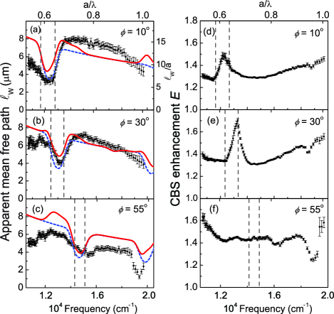
The CBS enhancement factors in Fig. 4(d) are consistently low compared to values obtained for strongly scattering random photonic media measured using the same instrument.muskensOE08 This behavior is particularly striking below the stop band, where photonic crystals are commonly expected to behave as an effective medium.Datta93 ; Genereux01 The enhancement factor ranges between 1.4 and 1.5, which is larger than values reported by Huang et al.HuangPRL01 but smaller than measured in Ref. [KoenderinkPLA, ]. A reduction of the enhancement factor below the stop band was also reported in Ref. Baumberg09, . The ideal enhancement factor of two is expected in any multiple scattering sample, whether absorbing and of finite size or not, as long as the sample obeys reciprocity. However, if scattering components contribute that have no distinct time reversed counterpart, such as single scattering, the enhancement factor is reduced.Mark88 In addition to this general trend, we find pronounced variations of around the stop gap. At the band edge, two sharp troughs appear in Fig. 4(d), which will be discussed further below.
Results obtained from CBS spectra for the nm opal at higher reduced frequencies are shown in Fig. 5. The spectra for the 180-nm opal yield more information on the behavior above the L-gap, covering values of between 0.55 and 1.03. Values of are around a factor three smaller for this opal than for the nm sample, which is indicative of an increased disorder. Apart from photonic band structure effects, we observe a gradual decrease of , which can be modeled using for the spectrum at . The power-law exponent is much lower than that observed in transmission measurements, emphasizing the nonuniversality of the mean free path in opal photonic crystals, as opposed to earlier suggestions.KoenderinkPRB05
Similar to the 130-nm opal, a distinct trough in is observed in Fig. 5 which shifts with the frequency of the stop gap for increasing angle of incidence. From the width of the stop gap, we estimate a Bragg length of around 5 m, indicating a ratio of for this more strongly disordered opal. We point out the asymmetry of both the mean free path and the enhancement factor over the stop band in Fig. 5(b). Such asymmetry cannot be explained by the group velocity behavior as this is symmetrical around the stop gap.Garcia09
At angles of incidence above [cf. Fig. 5(c)], a second trough in appears around 19000 cm-1. Comparison with the band structure calculations of Fig. 3 reveals that this feature can be attributed to another Bragg reflection at oblique planes, which appears around at the and points in the Brillouin zone. The presence of this band is also clearly observed as a trough in the enhancement factor in Fig. 5(f). The presence of this higher-order diffraction peak demonstrates that the observed behavior has to be described by the full 3D photonic band structure and not just by a simple one-dimensional Bragg reflector.
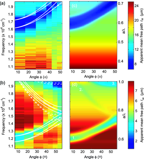
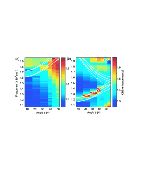
The extensive information on the diffuse scattering parameters obtained from CBS spectra taken at different angles and frequencies can be combined into maps of fitted values for and as shown in Figs. 6 and 7. Figures 6(a) and (b) show the experimental data, while Figures 6(c) and (d) are results from calculations discussed below in Sec. IV. The CBS enhancement is shown in Fig. 7. In the following section, we discuss the different contributions to the wavelength dependence of and in more detail.
IV Model calculation of band structure effects on angle-dependent CBS cone width
IV.1 General model for CBS-cone width
In this section we discuss the combined frequency and angle-dependence of the width of the CBS cone. Our starting point for the description of diffuse light scattering in the crystal is the theory for random photonic media that we extend for the effects of the photonic crystal band structure.KoenderinkPLA ; KoenderinkPRL03 According to predictions by Ref. [KoenderinkPLA, ], the cone width is modified by two effects: internal reflectionKoenderinkJOSAB and the limited penetration depth of the incident light when its wavelength matches the Bragg condition. A larger internal reflection results in longer paths, providing a narrowing of the CBS cone. In contrast, reduction of the penetration depth leads to shorter paths as the light has a larger probability to exit via the surface, resulting in a broadening of the cone. It has been shown that the resulting correction to the CBS cone can be included in the random diffusion model by introducing an apparent mean free path which is given byKoenderinkPLA
| (1) |
with
| (2) |
Here is the internal reflection coefficient integrated over all angles as put forward in the theory for multiple light scattering.Lagendijk89 ; Zhu91 The penetration depth of the incident light is included in the parameter . The Bragg length varies between infinity (no Bragg diffraction) and , with the photonic strength and the lattice constant in the (111)-direction. We use the extrapolation length ratios and that were originally derived for random media.Lagendijk89 ; Zhu91

IV.2 Internal reflection
We propose to capture the essential optical properties of the photonic crystals by the three dominant stop gaps. Therefore, the internal-reflection coefficient of the opals is modeled as the sum of three Gaussian reflection peaks
| (3) |
with angle-dependent peak reflectivities and widths and , with . Following earlier successful descriptions of the angle dependent reflectivities VanDiel2000 and escape functionKoenderinkPRL03 , we use the gaps along the LU high-symmetry direction to model the reflectivity, and assume a dependence on angle according to , where the cosine-dependence is based on simple Bragg diffraction. The frequencies are obtained from the calculated band edges in Fig. 3(d).
Using the three-gap model described by Eq. (3), the internal reflection is obtained by angle-averaging for every frequency using Lagendijk89 ; Zhu91 ; Durian96
| (4) |
with
| (5) |
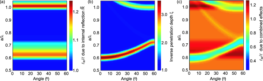
The resulting values of the internal reflection for an opal photonic crystal are shown in Fig. 8. The internal reflection due to photonic band structure ranges between zero and 14% in the frequency range of interest. We notice three peaks in the spectrum of , which can be attributed to the L-gap and the avoided crossing at the U and W points. The internal reflection contribution should not be confused with effects due to density of states, which also are independent of angle. There is a fundamental physical difference between these two physical parameters: the internal reflection coefficient is the result of gaps, in other words, of the absence of states. Conversely, the density of states is a sum over states, and is thus the result of the presence of states. Moreover, the variations in are much greater than those in the density of states, see Fig. 2(b) and Refs. [Nikolaev08, , Li01, ].
IV.3 Modification of diffuse source by Bragg diffraction
At the center of the stop gap, the following expression holds for the Bragg length in a two-band modelShung
| (6) |
The Bragg length varies between Eq. (6) at the Bragg condition and infinity outside the stop band. In absence of a theoretical description of , we assume here to be inversely proportional to the reflectivity around the stop gap
| (7) |
where is the internal reflection coefficient defined in Eq. (3) and is the photonic strength obtained from band structure calculations and experiments. This definition of is chosen as it provides the right value in the middle of the gap, the peak in follows the reflection coefficient as expected, and outside the reflection peaks becomes very large, as expected. Furthermore, a reduced reflection coefficient yields an increase of , which is qualitatively consistent with experiments by Vlasov et al. and Bertone et al.Vlasov99 ; Bertone99 More accurate modelling of is beyond the scope of our semi-empirical analysis.
The modification of the diffuse source by Bragg reflection is included in Eq. (1) through the parameter . The parameter can be identified as the inverse penetration depth of the light in the crystal due to Bragg reflection.KoenderinkPLA Below we will calculate the effect of photonic stop bands on for the opals under study. We note that the model presented for internal reflection here is a rigorous framework in multiple scattering theory, barring the introduction of a semi-empirical description of the band structure in Eq. (3) and Eq. (7). These approximations limit detailed comparison particularly at the edges of the stop band. Our model is highly constrained, as the only adjustable parameters that we allow to vary are the that are constant or very smoothly varying.
IV.4 Comparison with experiments
Using the model above, we will estimate the effects of the internal reflection and source distributions on the CBS cone width. Values of , , and were optimized to achieve good agreement with the experimental data of Fig. 6, yielding , , and . These four coefficients together with the overall scaling of the mean free path are the only adjustable parameters used to fit the data for all frequencies and incidence angles. The small value of is chosen since this band does not have a pronounced appearance in our experimental data. Figure 9(a) shows the effect of internal reflection only on . The increase of results in a narrowing of the cone and thus an increase of according to Eq. (1), which does not depend on angle of incidence . In contrast, the inverse penetration depth , shown in Fig. 9(b), follows the band structure according to Eq. (3).
The two contributions are combined to yield the apparent mean free path as shown in Fig. 6(c,d) for the two opals. For comparison with the experimental data, we included the power law dependence of the background mean free path in absence of photonic effects. The calculated maps for in Fig. 6 agree well with most of the experimental observations. The cross sections, shown as red lines in Figs. 4 and 5, reveal that the depth of the correction on closely matches the experimental behavior. However, the effect of internal reflection, predicted as an increase of before the stop band at larger angles, is not consistent with our experimental data. We note that effects of internal reflection are generally difficult to disentangle from smoothly varying corrections on of the order of 10%. The predominant modification of the cone width in the photonic crystals under study is caused by the reduction of the penetration depth, as is illustrated by calculations including only this correction (dashed lines, blue).
IV.5 Enhancement factor
Here, we will briefly discuss the remarkable behavior of the CBS-enhancement factor. After elimination of spurious background contributions to the intensity, variations in can only be caused by changes in the intensity and polarization of single-scattered light. The low enhancements at small reduced frequencies are particularly puzzling, since photonic crystals in the long wavelength limit are widely expected to behave as effective weakly scattering media.Datta93 ; Vos96 ; Genereux01 A similar reduction of in the long-wavelength limit was observed for thin slabs of nanowires, which was explained by the finite thickness of the layer of the order and the concomitant suppression of higher scattering orders.muskensNL09 For the current samples, in the long wavelength regime, is still larger than 15. Therefore we can exclude finite sample thickness as an origin for the low enhancement.
The effect of stop gaps on single scattering may be caused by changes in intensity or polarization of the single-scattered light. While absorption loss does not change the enhancement factor for an ideal experiment where only multiply scattered light is collected, absorption might influence via the ratio between single and multiply scattered light. However, absorption would also be apparent as a cone rounding. By analyzing the cone rounding, we note that the diffuse absorption length is equal to or even greater than the sample thickness, i.e. 200 m. This value corresponds to an absorption decay length of 6 mm, in agreement with our previous measurements.Vos01 Therefore, we conclude that the role of absorption loss is negligible.
Variations in the total scattering intensity are observed around the stop gap in our samples, as shown in Fig. 10, consistent with the behavior reported in other work.Astratov2002 ; Baumberg09 We see a minimum in the stop gap with two wings of high scattering at the band edges. Inside the stop gap, the Bragg reflection removes intensity from the diffuse scattering. This redistribution does not necessarily influence the CBS enhancement factor considering that the Bragg peak does not lead to additional single scattering. A decrease of the incoherent single scattering background in the stop gap may even be expected as single scattering from the photonic crystal coherently adds to the specular Bragg reflection and is thus suppressed at other angles. The overall increase of scattering intensity toward shorter wavelengths and larger angles of incidence is consistent with an increase of the enhancement factor which can be attributed to more efficient randomization of light in the medium.

Another pronounced feature in are the troughs at the band edges observed for the nm opal in Fig. 4(d). The conditions of these throughs appears correlated with presence of sharp peaks in the scattering intensity of Fig. 10(a), which currently is not explained by any models. These effects resemble the characteristic behavior of the group velocity as well as recent measurements of scattering mean free path.Garcia09 Such a reduction of the single scattering length at the band edges is not observed in the apparent mean free path of Fig. 4(c), as is averaged over many different directions in the crystal. We propose that the CBS enhancement factor is inherently more sensitive to directional band structure effects through its dependence on single-scattering, and therefore changes of can result in variations of . The large variations in observed in our experiment call for new theory for diffuse light in (partially) ordered nanophotonic materials.
Some of the variations in the CBS enhancement cannot be associated with the behavior of the total scattering intensity in Fig. 10, but may be associated to the use of circularly polarized light in our experiments. Markedly, there is the drop in associated with the second stop band at . This opposite behavior to the increase of in the L-gap points to a difference in helicity of single scattering, possibly due to Brewster angle effects.Baryshev06 For the L-gap at , the parallel and perpendicular components perceive exactly the same Bragg reflectivities and thus no change of the polarization state of circularly polarized incident light should occur. Strong polarization dependence of light transmitted and reflected from opals was identified in several studies.Galisteo2003 ; Baryshev06 ; Romanov2009 Polarization effects have also been found in Ref. Baumberg09, , where in particular cross-polarized CBS cones were reported. Our measurements of the cross-polarized channel only showed an angle-independent response; no cross-polarized CBS cones were detected.
V Conclusions
We have investigated multiple scattering of light in three-dimensional polystyrene opal photonic crystals using white-light coherent backscattering spectroscopy. Our experiments significantly extend on earlier measurements by covering simultaneously a large frequency and angular range. The measurements of the backscattering cone width at frequencies near the stop bands confirm the model by Refs. [KoenderinkPLA, ; KoenderinkJOSAB, ] which includes internal reflection and the limited penetration depth of the incident light. The semi-empirical model matches the experiments without the need to include effects of density of states or group velocity, such as were proposed in Ref. [Garcia09, ]. In addition, we report photonic band structure contributions in the CBS enhancement factor. We propose that the CBS enhancement factor, being particularly sensitive to single scattering, thus contains information on properties which are washed out in other aspects of the multiple scattering CBS cone. A better understanding of group velocity and other band structure effects to the enhancement factor will require further theoretical studies.
The presented experimental approach using white-light coherent backscattering opens up studies on diffuse light transport in novel materials. Future investigations may look toward stronger scattering photonic crystals such as TiO2 or silicon inverse opals or silicon inverse woodpilesHuisman10 , for which effects of the density of states could be observable. Other examples where the interplay of disorder - or reduced symmetry - and band structure is expected to result in novel phenomena are photonic quasicrystalsLederman09 and optical graphene.Segev09 ; BeenakkerEPL09
VI Acknowledgements
We thank A. Lagendijk for fruitful discussion and access to experimental equipment. This work is part of the research program of the ”Stichting voor Fundamenteel Onderzoek der Materie (FOM)”, which is financially supported by the ”Nederlandse Organisatie voor Wetenschappelijk Onderzoek (NWO)”. WLV thanks NWO-Vici and Smartmix Memphis, AFK thanks NWO-Vidi for financial support. OLM is supported by HEFCE through a SEPnet lectureship.
References
- (1) J. D. Joannopoulos, S. G. Johnson, J. N. Winn, R. D. Meade, Photonic crystals: molding the flow of light, 2nd ed. (Princeton University Press, 2008).
- (2) E. Yablonovitch, Phys. Rev. Lett. 58, 2059 (1987).
- (3) S. John, Phys. Rev. Lett. 58, 2486 (1987).
- (4) Z.-Y. Li and Z.-Q. Zhang, Phys. Rev. B 62, 1516 (2000).
- (5) Y. A. Vlasov, V. N. Astratov, A. V. Baryshev, A. A. Kaplyanskii, O. Z. Karimov, and M. F. Limonov, Phys. Rev. E 61, 5784 (2000).
- (6) A. F. Koenderink, M. Megens, G. van Soest, W. L. Vos, and A. Lagendijk, Phys Lett. A 268, 104-111 (2000).
- (7) J. Huang, N. Eradat, M. E. Raikh, Z.V. Vardeny, A. A. Zakhidov, and R.H. Baughman, Phys. Rev. Lett. 86, 4815-4818 (2001).
- (8) V.N. Astratov, A.M. Adawi, S. Fricker, M. S. Skolnick, D.M. Whittaker, and P.N. Pusey, Phys. Rev. B 66, 165215 (2002).
- (9) S. Ogawa, K. Tomoda, and S. Noda, J. Appl. Phys. 91, 513 (2002).
- (10) A. F. Koenderink and W. L. Vos, Phys. Rev. Lett. 91, 213902 (2003).
- (11) M. Allard and E. H. Sargent, Appl. Phys. Lett. 85, 5887 (2004).
- (12) R. Rengarajan, D. Mittleman, C. Rich, and V. Colvin, Phys. Rev. E 71, 016615 (2005) .
- (13) P.D. García, R. Sapienza, L. S. Froufe-Pérez, and C. López, Phys. Rev. B 79, 241109 (2009).
- (14) R. J. P. Engelen, D. Mori, T. Baba, and L. Kuipers, Phys. Rev. Lett. 101, 103901 (2008).
- (15) J. Topolancik, B. Ilic, and F. Vollmer, Phys. Rev. Lett. 99, 253901 (2007).
- (16) L. Sapienza, H. Thyrrestrup, S. Stobbe, P. D. Garcia, S. Smolka, and P. Lodahl , Science 327,1352 (2010).
- (17) M.V. Erementchouk, L.I. Deych, H. Noh, H. Cao, and A. A. Lisyansky, J. Phys: Cond. Mat. 21, 175401 (2009).
- (18) C. Toninelli, E. Vekris, G. A. Ozin, S. John, and D. S. Wiersma, Phys. Rev. Lett. 101, 123901 (2008).
- (19) The Bragg length describes how many crystal layers are required for Bragg interference, and is directly related to the photonic strength parameter , for a description see e.g. A.F. Koenderink, Phd thesis, University of Amsterdam (2003).
- (20) T. Schwartz, G. Bartal, S. Fishman, and M. Segev, Nature 446, 52-55 (2007).
- (21) O.L. Pursiainen, J.J. Baumberg, H. Winkler, B. Viel, P. Spahn, and T. Ruhl, Optics Express, 15, 9553 (2007).
- (22) J. J. Baumberg, O. L. Pursiainen, and P. Spahn, Phys. Rev. B 80, 201103R (2009).
- (23) O. L. Muskens and A. Lagendijk, Opt. Express 16, 1222 (2008).
- (24) O. L. Muskens, S. L. Diedenhofen, R. Algra, E. P. A. M. Bakkers, B. Kaas, and A. Lagendijk, Nano Lett. 9, 930 (2009).
- (25) W. L. Vos, R. Sprik, A. van Blaaderen, A. Imhof, A. Lagendijk, and G. H. Wegdam, Phys. Rev. B 53, 16231 (1996).
- (26) W.L. Vos, M. Megens, C.M. van Kats, and P. Bösecke, Langmuir 13, 6004 (1997).
- (27) Z.-Y. Li and Z.-Q. Zhang, Phys. Rev. B 63, 125106 (2001).
- (28) I. S. Nikolaev, P. Lodahl, and W. L. Vos, J. Phys. Chem. C 112, 7250 (2008).
- (29) A.F. Koenderink, A. Lagendijk, and W. L. Vos, Phys. Rev. B 72, 153102 (2005).
- (30) H. M. van Driel and W. L. Vos, Phys. Rev. B 62, 9872 (2000).
- (31) S. G. Romanov, T. Maka, C. M. Sotomayor Torres, M. Muller, R. Zentel, D. Cassagne, J. Manzanares-Martinez, and C. Jouanin, Phys. Rev. E 63, 056603 (2001).
- (32) J. F. Galisteo-López, and C. López, Phys. Rev. B 70, 035108 (2004).
- (33) E. Pavarini, L. C. Andreani, C. Soci, M. Galli, F. Marabelli, and D. Comoretto, Phys. Rev. B 72, 045102 (2005).
- (34) M. B. van der Mark, M. P. van Albada, and A. Lagendijk, Phys. Rev. B 37, 3575 (1988).
- (35) Y. A. Vlasov, M. A. Kaliteevski, and V. V. Nikolaev, Phys. Rev. B 60, 1555 (1999).
- (36) Ì. Ì. Tarhan and G. H. Watson, Phys. Rev. Lett. 76, 315 (1996).
- (37) C. Koerdt, G. L. J. A. Rikken, and E. P. Petrov, Appl. Phys. Lett. 82, 1538 (2003).
- (38) R. D. Pradhan, J. A. Bloodgood, and G. H. Watson, Phys. Rev. B 55, 9503 (1997).
- (39) H. Míguez, C. López, F. Meseguer, A. Blanco, L. Vazquez, R. Mayoral, M. Ocana, V. Fornes, and A. Mifsud, Appl. Phys. Lett. 71, 1148 (1997).
- (40) S. H. Park, B. Gates, and Y. N. Xia, Adv. Mater. 11, 462 (1999).
- (41) S. Datta, C. T. Chan, K. M. Ho, and C. M. Soukoulis, Phys. Rev. B. 48, 14936 (1993).
- (42) F. Genereux, S. W. Leonard, H. M. van Driel, A. Birner and U. Gosele, Phys. Rev. B 63, 161101 (2001).
- (43) K. W.-K. Shung and Y. C. Tsai, Phys. Rev. B 48, 11265 (1993).
- (44) J. F. Bertone, P. Jiang, K. S. Hwang, D. M. Mittleman, and V. L. Colvin, Phys. Rev. Lett. 83, 300 (1999).
- (45) A.F. Koenderink and W. L. Vos, J. Opt. Soc. Am. B 22, 1075 (2005).
- (46) A. Lagendijk, R. Vreeker, and P. de Vries, Phys. Lett. A 136, 81 (1989).
- (47) J. X. Zhu, D. J. Pine, and D. A. Weitz, Phys. Rev. A 44, 3948 (1991).
- (48) M. U. Vera and D. J. Durian, Phys. Rev. E 53, 3215 (1996).
- (49) Yu. A. Vlasov, V. N. Astratov, O.Z. Karimov, and A. A. Kaplyanskii, V. N. Bogomolov, and A. V. Prokofiev, Phys. Rev. B 55, 13357 (1997).
- (50) J. F. Galisteo-Lopez, F. López-Tejeira, S. Rubio, C. López, and J. Sánchez-Dehesa, Appl. Phys. Lett. 82, 4068 (2003).
- (51) W.L. Vos, H.M. van Driel, M. Megens, A.F. Koenderink, and A. Imhof, Experimental probes of the optical properties of photonic crystals, In: Photonic Crystals and Light Localization in the 21st Century, ed. C.M. Soukoulis (Kluwer, Dordrecht, 2001) 191-218.
- (52) A.V. Baryshev, A. B. Khanikaev, H. Uchida, M. Inoue, and M. F. Limonov, Phys. Rev. B 73, 033103 (2006).
- (53) S. G. Romanov, Phys. Sol. State 52, 844 (2009).
- (54) B. Freedman, G. Bartal, M. Segev, R. Lifshitz, D. N. Christodoulides, and J. W. Fleischer, Nature 440, 1166 (2006).
- (55) S.R. Huisman, R.V. Nair, L.A. Woldering, M.D. Leistikow, A.P. Mosk, and W.L. Vos, Arxiv:1012.5263 (2010).
- (56) A. Ledermann, D. S. Wiersma, M. Wegener, and G. von Freymann, Opt. Express 17, 1844 (2009).
- (57) O. Bahat-Treidel, O. Peleg, M. Grobman, N. Shapira, M. Segev, and T. Pereg-Barnea, Phys. Rev. Lett. 104, 063901 (2010).
- (58) R. A. Sepkhanov, A. Ossipov, and C. W. J. Beenakker, Eur. Phys. Lett. 85, 14005 (2009).