Resonant Electron Transport in Single-Molecule Junctions: Vibrational Excitation, Rectification, Negative Differential Resistance and Local Cooling
Abstract
Vibronic effects in resonant electron transport through single-molecule junctions are analyzed. The study is based on generic models for molecular junctions, which include electronic states on the molecular bridge that are vibrationally coupled and exhibit Coulomb interaction. The transport calculations employ a master equation approach. The results, obtained for a series of models with increasing complexity, show a multitude of interesting transport phenomena, including vibrational excitation, rectification, negative differential resistance (NDR) as well as local cooling. While some of these phenomena have been observed or proposed before, the present analysis extends previous studies and allows a more detailed understanding of the underlying transport mechanisms. In particular, it is shown that many of the observed phenomena can only be explained if electron-hole pair creation processes at the molecule-lead interface are taken into account. Furthermore, vibronic effects in sytems with multiple electronic states and their role for the stability of molecular junctions are analyzed.
pacs:
73.23.-b,85.65.+h,71.38.-kI Introduction
For more than a decade, molecular electronics Nitzan (2001); Cuniberti et al. (2005); Selzer and Allara (2006); Tao (2006); Venkataraman et al. (2006); Chen et al. (2007); Galperin et al. (2008); van der Molen and Liljeroth (2010); Cuevas and Scheer (2010) has been a very active and challenging field of research. One of the basic ideas is to exploit the diversity of molecules and the possibilities of modern synthesis to design molecular systems with specific functions for nanoscale electronic devices. Another motivation is the possibility to investigate single molecules under controllable nonequilibrium conditions. Various techniques, including mechanically controlled break junctions Reed et al. (1997); Reichert et al. (2002); Smit et al. (2002); Böhler et al. (2004); Elbing et al. (2005); Martin et al. (2010), electro-migrated molecular junctions Yu et al. (2004); Sapmaz et al. (2005, 2006); de Leon et al. (2008); Hüttel et al. (2009); Osorio et al. (2010), scanning tunneling microscopy Stipe et al. (1998); Wu et al. (2004); Ogawa et al. (2007); Schulze et al. (2008); Pump et al. (2008); Hihath et al. (2010), and very recently, on-wire lithography in combination with in-situ ’click chemistry’ Mayor (2009); Chen et al. (2009), have been employed to contact a single molecule with two macroscopic electrodes. Once such a molecular junction is established, external electric fields, either a bias or a gate voltage Sapmaz et al. (2005); Song et al. (2009); Osorio et al. (2010); Martin et al. (2010), can be used to investigate the conductance of a single molecule. A variety of interesting transport phenomena have been proposed and experimentally observed Selzer and Allara (2006); Tao (2006); Yeganeh et al. (2007); Chen et al. (2007); van der Molen and Liljeroth (2010); Cuevas and Scheer (2010), including, e.g., switching behavior Lörtscher et al. (2006); Choi et al. (2006); Meded et al. (2009); Benesch et al. (2009), rectification Wu et al. (2004); Elbing et al. (2005); Diez-Perez et al. (2009) and negative differential resistance Gaudioso et al. (2000); LeRoy et al. (2004); Pop et al. (2005); Sapmaz et al. (2005, 2006); Osorio et al. (2010).
However, a detailed understanding of the experimental results, especially in the resonant transport regime, where electrons may populate an intermediate state on the bridging molecule, has not been achieved yet. One of the interesting and challenging aspects of electron transport in molecular junctions is the intricate interplay between the electronic and vibrational degrees of freedom. Because of the small size of molecules, the charging of the molecular bridge is often accompanied by significant changes of the nuclear geometry that indicate strong coupling between electronic and vibrational degrees of freedom. As a consequence, the vibrational modes of a molecular junction can be highly excited resulting in significant nonequilibrium effects Härtle et al. (2008, 2009); Romano et al. (2010); Härtle et al. (2010). This aspect distinguishes single-molecule junctions from traditional quantum dot systems Reed et al. (1988); Holleitner et al. (2001); Kubala and König (2002); Muralidharan and Datta (2007). Vibrational signatures indicating strong vibronic coupling as well as strong excitation of vibrational modes were identified for a number of molecular junctions Wu et al. (2004); LeRoy et al. (2004); Yu et al. (2004); Pasupathy et al. (2005); Sapmaz et al. (2006); Thijssen et al. (2006); Parks et al. (2007); Böhler et al. (2007); de Leon et al. (2008); Hüttel et al. (2009); Hihath et al. (2010); Ballmann et al. (2010); Jewell et al. (2010); Osorio et al. (2010). Novel experimental techniques based on measuring the force needed to break a junction Huang et al. (2006) or employing Raman spectroscopy Ward et al. (2008); Ioffe et al. (2008) allow a characterization of the current-induced vibrational nonequilibrium state of a single-molecule junction. These data complement the information carried by the respective current-voltage characteristics.
Various theoretical approaches have been employed to describe vibrationally coupled electron transport through single molecules. While scattering theory approaches Cizek et al. (2004); Caspary Toroker and Peskin (2007); Zimbovskaya and Kuklja (2009); Jorn and Seidemann (2009) can be used to address the regime of strong molecule-lead coupling, nonequilibrium Green’s function approaches Flensberg (2003); Mitra et al. (2004); Galperin et al. (2006a); Ryndyk et al. (2006); Frederiksen et al. (2007); Tahir and MacKinnon (2008); Härtle et al. (2008); Bergfield and Stafford (2009); Härtle et al. (2009) additionally allow a non-perturbative description of the associated nonequilibrium state of such a junction, especially with respect to the vibrational degrees of freedom. Numerically exact methods, based on path integrals Mühlbacher and Rabani (2008); Weiss et al. (2008) or multiconfigurational wave-function methods Wang and Thoss (2009), provide valuable insights and benchmarks for specific model systems and problems that may not be addressed by perturbation theory or other approximative schemes. Master equation approaches May (2002); Mitra et al. (2004); Lehmann et al. (2004); Pedersen and Wacker (2005); Harbola et al. (2006); Zazunov et al. (2006); Siddiqui et al. (2007); Timm (2008); May and Kühn (2008a, b); Leijnse and Wegewijs (2008); Esposito and Galperin (2009); Esp , although perturbative with respect to the coupling between the molecule and the leads, have been proven to be very powerful, as they are capable of describing all interactions on the molecular bridge accurately and, for simple model systems, very efficiently. In this work, we employ a master equation approach that is based on a second order expansion in the molecule-lead coupling Mitra et al. (2004); Lehmann et al. (2004); Harbola et al. (2006). Master equation approaches that take into account higher-order effects with respect to this coupling have already been employed May (2002); Pedersen and Wacker (2005); Leijnse and Wegewijs (2008); Esposito and Galperin (2009); Esp . The corresponding higher-order transport processes König et al. (1996); Paaske and Flensberg (2005); Galperin et al. (2007); Lüffe et al. (2008); Härtle et al. (2008); Leijnse et al. (2009); Han (2010), however, are beyond the scope of this work, where we focus on the resonant transport regime.
In this article, we analyze nonequilibrium transport phenomena induced by electronic-vibrational coupling in molecular junctions. To this end, we consider generic models for vibrationally coupled electron transport including electronic states on the molecular bridge that are vibrationally coupled and exhibit Coulomb interaction. The results show a multitude of interesting phenomena that extend previous studies and may facilitate the interpretation of experimental results. In particular, it is found that the current-induced vibrational excitation in transport through a molecular bridge with a single electronic state increases significantly with increasing bias voltage and/or decreasing electronic-vibrational coupling. We show that this phenomenon is caused by electron-hole pair creation processes Persson and Ueba (2002); Mii et al. (2002); not (a), which to the best of our knowledge have not been considered in detail in this context before. Further analysis shows that electron-hole pair creation processes can also explain the strong enhancement of vibrational rectification effects in situations where the vibrational degree of freedom acquires a highly excited nonequilibrium state. This complements the analysis of the phenomenon of vibrational rectification given in Ref. Flensberg, 2003. Electronic-vibrational coupling may also cause vibrationally induced NDR effects Boese and Schoeller (2001); Koch and von Oppen (2005); Zazunov et al. (2006); Leijnse and Wegewijs (2008). In this work, we reinterpret the NDR-mechanism outlined in Refs. Boese and Schoeller, 2001; Zazunov et al., 2006 in terms of pair creation processes. Furthermore, a novel mechanism for vibrationally induced NDR is discussed, which, in contrast to earlier studies Hettler et al. (2002, 2003); Muralidharan and Datta (2007), extends over a broad range of bias voltages.
In molecular junctions, where multiple electronic states participate in the charge transport, a number of additional vibronic processes have to be considered. In particular, as we have shown recently Härtle et al. (2009), higher-lying electronic states facilitate resonant absorption processes that may deexcite the vibrational degrees of freedom. This mechanism reduces the current-induced vibrational excitation of a molecular junction and results in local cooling Härtle et al. (2009); Romano et al. (2010). In the present paper, we give a detailed analysis of effects due to multiple electronic states. In this context, we also show that repulsive Coulomb interactions may further enhance the stability of a molecular junction (cf. III.2.3). We refer to this phenomenon as ’Coulomb Cooling’. Since polyatomic molecules typically include numerous active vibrational modes and often exhibit multiple closely lying electronic states, these phenomena are expected to be of relevance for most molecular junctions.
The article is organized as follows. In Section II.1 we introduce the model Hamiltonian used to describe electron transport through a single-molecule junction. The derivation of the master equation approach and expressions for the observables of interest, in particular, current-voltage characteristics and the average vibrational excitation of a molecular junction, are outlined in Secs. II.2 and II.3. Explicit formulas adapted to the specific model systems are detailed in appendices A and B. The role of coherences is elucidated in appendix C. Sec. III comprises numerical results and a discussion of the different transport phenomena. Thereby, we consider transport phenomena that involve a single electronic state (Sec. III.1) and two electronic states (Sec. III.2). Besides the basic transport mechanisms that are discussed in Sec. III.1.1 and III.2.1, we study vibrationally induced rectification in Secs. III.1.2 and III.2.2 as well as vibrationally induced negative differential resistance in Secs. III.1.3 and III.2.4. Vibrational excitation processes in junctions with two electronic states and their influence on the stability of a molecular junction are analyzed in Secs. III.2.1 to III.2.3. Throughout the article we use units where .
II Theory
II.1 Model Hamiltonian
We consider electron transport through a single molecule that is bound to two metal leads. Such a molecular junction is described by a set of discrete electronic states, which are localized on the molecular bridge (M) and interact with a continuum of electronic states in the left (L) and the right (R) lead, respectively. The corresponding model Hamiltonian is given by
Thereby, denote the energies of the lead states with corresponding creation and annihilation operators and . Likewise, is the energy of the th electronic state on the molecular bridge, which is addressed by creation and annihilation operators and . The coupling matrix elements characterize the strength of the interaction between the electronic states of the molecular bridge and the leads and determine the so-called level-width functions (=L,R).
Additional charging energies, due to Coulomb interactions, are accounted for by Hubbard-like electron-electron interaction terms, . Thereby, the parameters distinguish states that are occupied () or unoccupied () in the molecular system at equilibrium. While in the present study we use a generic model, the first-principles determination of the parameters requires the introduction of a reference system Benesch et al. (2008). In the present paper, we consider the neutral molecule in its electronic ground state as a reference system. As a result, for an electronic state above the Fermi-level (), the associated energy denotes the energy required to add an electron to the th electronic state of the reference system. For an electronic state below the Fermi-level (), denotes the energy required to remove an electron from state , in accordance with Koopmans’ theorem. The Fermi energy of the leads is set to eV.
Upon transmission of electrons, the molecular bridge may be vibrationally excited. We describe the vibrational degrees of freedom of a molecular junction within the harmonic approximation,
| (2) |
where the operator denotes the creation operator of the th oscillator with frequency . The coupling between the electronic and the vibrational degrees of freedom is assumed to be linear in both the vibrational displacements and the electron (or hole) densities Cederbaum and Domcke (1974); Benesch et al. (2008); Han (2010). The respective coupling strengths are denoted by . Because we employ the normal modes of the ground-state of the neutral molecule, there is no coupling between the electronic states and the normal modes of the molecular junction in this state. This is imposed in the electronic-vibrational coupling term by the parameters . The Hamilton operator of the overall system is given by the sum
| (3) |
In the limit of vanishing molecule-lead coupling, , the Hamiltonian can be diagonalized by the small polaron transformation Mahan (1981); König et al. (1996); Mitra et al. (2004); Härtle et al. (2008)
| (4) | |||||
with
| (5) | |||||
| (6) |
Thereby, we have partitioned the transformed Hamiltonian in three parts, , with representing the molecular bridge, the leads and describing the interactions between the molecular bridge and the leads. Due to the small-polaron transformation, there is no explicit electronic-vibrational coupling in . However, electronic-vibrational coupling appears in the transformed Hamiltonian at three different places:
-
•
in the polaron-shifted energies: ,
-
•
in additional electron-electron interactions, which shift the original electron-electron interaction terms: ,
-
•
and in the molecule-lead coupling term that is renormalized by the shift operators .
II.2 Master equation approach
Density matrices have been proven to be a powerful tool in describing quantum-mechanical systems Blum (1981); Louisell (1973); Davidson (1976); Weiss (1993); May and Kühn (2004). Once the density matrix of a given system is known, all observables of that system can be obtained from the trace
| (7) |
Thereby, the elements of the density matrix are given as , where and are elements of a complete set of orthonormal basis functions that span the Hilbert space of the overall system. Since Eq. (7) is invariant under the small polaron transformation, we consider in the following as the Hamiltonian of the system.
The time-evolution of a density matrix is determined by the Liouville - von Neumann equation:
| (8) | |||||
| (9) |
where the initial state at time is encoded in the respective density matrix . Here, denotes the Liouville operator .
To describe an open quantum system such as a single molecule coupled to a reservoir of electrons (in the left and the right electrode), it is expedient to employ the reduced density matrix of this system , which is obtained by taking the trace over the degrees of freedom of the reservoirs (or baths (B)),
| (10) |
Formally, this can be achieved by the projection operator
| (11) |
and its orthogonal complement . Here, denotes the thermal equilibrium density matrix of the reservoir
| (12) |
Assuming a factorized initial condition , the equation of motion for the reduced density matrix is given by the Nakajima-Zwanzig equation Nakajima (1958); Zwanzig (1960)
which represents a formally exact equation. For practical applications, approximations are required to solve this equation of motion. In the present context, we assume that the molecule-lead coupling, , is weak. Employing a second order expansion in and the condition , the Nakajima-Zwanzig equation can be simplified to the master equation May (2002); Egorova et al. (2003); Mitra et al. (2004); Lehmann et al. (2004)
with
| (15) |
To obtain the time-local master equation described by Eq. (II.2), we have, furthermore, employed the Markov approximation, which involves the shift of the integration limit and the replacement
| (16) |
The latter approximation is in line with the second order expansion in . Due to the shift in the integration limit, the master equation (II.2) is only valid for times longer than the correlation time of the bath Egorova et al. (2003); Volkovich et al. (2008); not (b). This is the case for the applications to steady-state transport considered in this paper, where only the long-time limit is required. Taken in the basis of eigenstates of the system Hamiltonian , the master equation (II.2) corresponds to the Redfield equation Redfield (1965); Blum (1981); May and Kühn (2004).
In the steady state transport regime, the above equation of motion becomes an algebraic set of equations
which can be solved by standard linear algebra techniques. Thereby, the normalization constraint ensures a unique solution.
As discussed in the Introduction, the master equation (II.2) as well as its steady-state form, Eq. (II.2), is valid for small molecule-lead coupling. Due to the neglect of terms of higher order in the system-reservoir coupling, it cannot describe tunneling in the non-resonant transport regime and misses the broadening of resonances due to this coupling. Except for these deficiencies, however, it provides a rather accurate description of vibrationally coupled electron transport in the resonant transport regime considered in this work. This has been demonstrated recently by comparison with results of nonequilibrium Green’s function (NEGF) methods Härtle et al. (2009). Test calculations show that all effects discussed in this work are also obtained with NEGF methods for vibrationally coupled resonant electron transport Galperin et al. (2006a); Härtle et al. (2008, 2009).
The basis functions, which we use to evaluate the reduced density matrix and the master equation Eq. (II.2), are products of basis functions that span the subspace of the electronic and the vibrational degrees of freedom , respectively. Thereby, the electronic basis functions are given in the occupation number representation i.e. , where denotes the population of the th electronic state. Throughout this article we consider a single vibrational mode with frequency . Hence, we represent the vibrational basis functions by harmonic oscillator basis functions , where stands for the excitation number of the vibrational mode. Thus, the coefficients of the reduced density matrix can be written as
| (18) |
where upper case indices refer to states of the vibrational mode and lower case indices represent the electronic part of the respective Hilbert space.
Evaluating Eq. (II.2) first between vibrational states and , we obtain the equation
| (19) | |||
with
Here, denotes the Fermi distribution function of the respective lead, L or R, evaluated at energy , and stands for the Dirac-delta function, where e.g. . In Eq. (19), we have neglected all principal value terms. These terms describe the renormalization of the molecular energy levels due to the molecule-lead coupling Harbola et al. (2006), which are negligible for the results discussed below. The thus obtained scheme represents a rate equation approach Mitra et al. (2004); Koch et al. (2006); Siddiqui et al. (2007).
In the next step, Eq. (19) is evaluated with respect to the electronic basis functions. Since there is no further approximations involved, we present the rather lengthy expressions in appendices A and B, where the results for a single electronic state and two electronic states can be found, respectively.
II.3 Observables of interest
II.3.1 Electronic population and vibrational excitation
The diagonal elements of the density matrix, , encode the probability of finding the system in the product state . Hence, for a single electronic state on the molecular bridge the occupation of this state is given by the expression
For two electronic states , the respective populations are given by
| (21) | |||||
Thereby, the subscript / denotes the Hamiltonian, which is used to evaluate the respective expectation value.
The average excitation of the vibrational mode involves a sum over all electronic degrees of freedom. For the transport scenario with a single electronic state on the molecular bridge, the average vibrational excitation reads
and respectively for the transport scenario with two electronic states
Since both operators and act in the subspace of the molecular bridge, the corresponding observables are fully determined by the reduced density matrix . This is not the case for the current operator, which encompasses the bridge space and the subspace of the leads.
II.3.2 Current
The current through lead , , is determined by the number of electrons entering or leaving the lead per unit time ()
Here, the constant () denotes the electron charge and the factor accounts for spin-degeneracy. The specific structure of the current operator requires the determination of , since . This projection of the full density matrix has already been used to derive Eq. (II.2) Nakajima (1958); Zwanzig (1960), and reads
Using Eq. (II.3.2) to evaluate the expression for the current, Eq. (II.3.2), and employing the same approximations that were used for the derivation of the master equation, Eq. (II.2), the following expression for the current through lead is obtained May (2002); Mitra et al. (2004); Lehmann et al. (2004); Harbola et al. (2006)
| (26) |
In the numerical calculations, Eq. (26) is further evaluated within the appropriate basis functions. The explicit formulas are given in appendices A and B. We note that the scheme described above is current conserving, i.e. .
II.4 Vibration in thermal equilibrium
To analyze and identify vibrational nonequilibrium effects, it is often instructive to compare the results of Eqs. (II.2) and (26) with those, where the vibrational degree of freedom of the molecular bridge is treated as a reservoir’s degree of freedom. To this end, we define a new projection operator
| (27) | |||||
| (28) |
where
| (29) |
The thus defined reduced density matrix describes the electronic degrees of freedom on the molecular bridge. Analogously to Eq. (II.2) and following the same steps as outlined in Section II.2, we obtain the following master equation
with
| (32) |
Treating the vibrational mode as a reservoir’s degree of freedom does not exclude the possibility to excite or deexcite it. However, it is assumed that such a nonequilibrium state relaxes on a short time scale to the thermal equilibrium state. This can be realized, e.g., by a strong coupling of the vibrational mode to a thermal bath.
III Results
We have applied the methodology outlined above to various models of vibrationally coupled electron transport in molecular junctions. The results described in this Section are structured according to the complexity of the models employed and the associated transport mechanisms. In Sec. III.1 and B we present results for transport through a molecular bridge with a single and two electronic states, respectively. Within each of these subsections, we study first symmetric molecular junctions, proceeding with asymmetrically coupled junctions, and finally discuss, for transport through two electronic states, the influence of electron-electron interactions.
In all cases considered the electronic states are coupled to a single vibrational mode with frequency eV. To represent the vibrational degree of freedom, the calculations employ vibrational basis functions, which provide converged results for all observables and parameters considered in this section. As is shown in appendix C, vibrational coherences have no significant effect and are therefore neglected in these calculations. The temperature of the leads is set to K in all calculations, since most experiments on molecular junctions are carried out at low temperatures. The same temperature is used for the vibrational mode in those calculations, where the vibration is treated in thermal equilibrium.
III.1 Transport through a molecular junction with a single electronic state
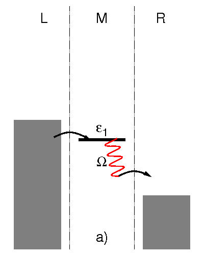
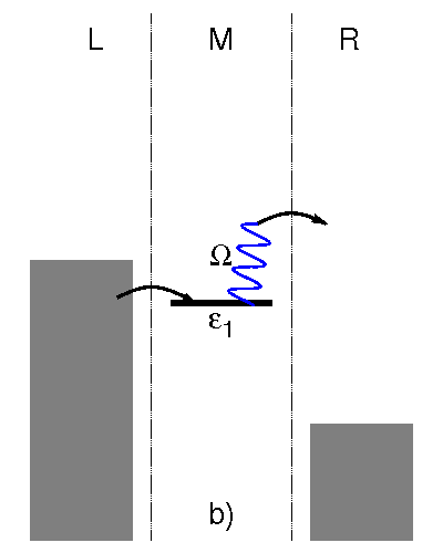
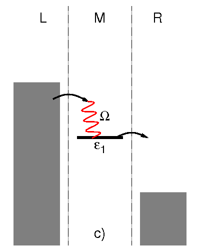
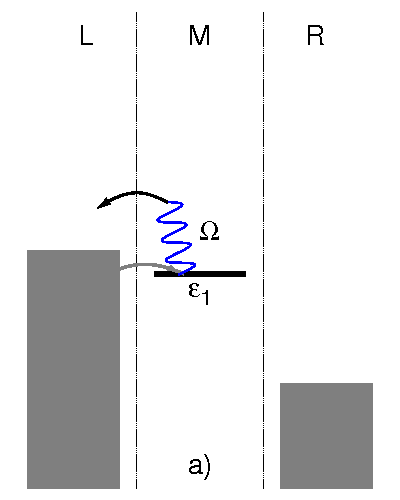
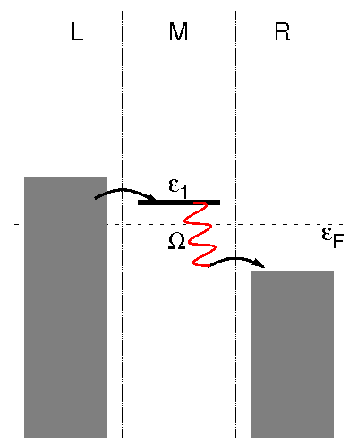
In this section we discuss vibronic effects in transport through a molecular junction that involves a single electronic state and a single vibrational mode. We start with a summary of the basic mechanisms of resonant emission and absorption processes (sketched in Figs. 1 and 2) for transport through a state that is symmetrically coupled to the leads. Furthermore, we discuss vibrationally induced rectification Braig and Flensberg (2003); Wu et al. (2004) and vibrationally induced negative differential resistance (NDR) Boese and Schoeller (2001); Koch and von Oppen (2005); Zazunov et al. (2006); Shen et al. (2007); LeRoy et al. (2004); Sapmaz et al. (2005, 2006); Leijnse and Wegewijs (2008) for junctions with asymmetric coupling to the leads. Understanding these generic mechanisms facilitates the discussion of transport through two electronic states in Sec. III.2 and extends our previous studies Härtle et al. (2008, 2009, 2010). In particular, we show that the vibrational excitation of a molecular junction can only be understood if electron-hole pair creation processes are considered (cf. Fig. 2) Persson and Ueba (2002); Mii et al. (2002); not (a). Furthermore, the results demonstrate that vibrationally induced rectification is strongly enhanced, if the vibrational degree of freedom, due to current-induced local heating, is in a highly excited nonequilibrium state.
III.1.1 Basic mechanisms
We first consider a model with a single electronic state at the molecular bridge with energy eV and a moderate coupling to the vibrational mode, eV. The left and the right leads are modelled as one-dimensional semi-infinite tight-binding chains with a semi-elliptic conduction band, for which the respective level-width functions read
| (36) | |||||
Here, eV denote the coupling strengths of the left and the right tight-binding chain to the electronic state at the molecular bridge and eV determines the band-width in both leads. The difference of the chemical potentials of the leads, , determines the applied bias voltage , which we assume to drop symmetrically at the contacts, i.e. .
Fig. 3 shows the corresponding current-voltage characteristics, the population of the electronic state at the molecular bridge (inset of Fig. 3b) and the vibrational excitation of this system. To facilitate the discussion, the dashed line depicts results for a purely electronic calculation without vibronic coupling (). The corresponding current exhibits a single step at the bias voltage , indicating that for electrons from the left lead can resonantly tunnel onto the electronic state and further to the right lead. These resonant transmission processes result in a current of A.
|
|
|
|
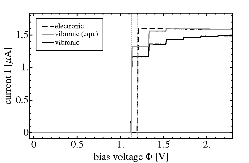
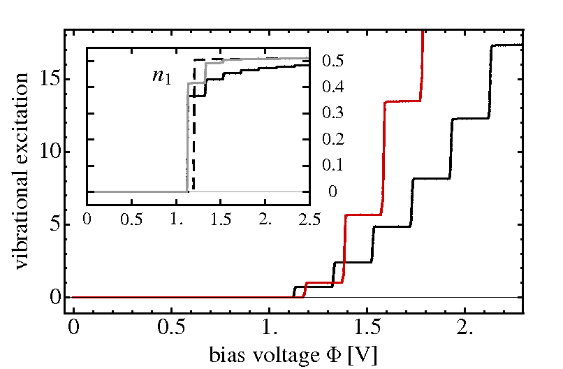
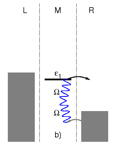
The current-voltage characteristics and the vibrational excitation for a finite vibronic coupling strength of eV are depicted by the solid black lines. For this case, the current rises in a multitude of steps. The first step appears at a lower bias voltage , reflecting the polaron shift of the electronic state. The following steps appear at voltages with and a step height that gradually decreases with increasing bias voltage. The first step at also marks the onset of resonant transport, where electrons from the left lead can resonantly tunnel onto the electronic state at the molecular bridge, accompanied by a transition from the initial vibrational state of the neutral molecule to the same vibrational state of the charged molecule. In a successive tunneling process from the molecular bridge to the right lead, which completes the transport process, the electronic-vibrational coupling may result in excitation (Fig. 1a) or deexcitation (Fig. 1b) of the vibrational mode. At this bias voltage, there are excitation (emission) processes available (corresponding to the excitation of at most vibrational quanta, as e.g. in Fig. 1a), and a number of deexcitation (absorption) processes (Fig. 1b). For larger bias voltages, , electrons can excite the vibration upon tunneling from the left lead onto the molecule (Fig. 1c), resulting in an increase of current and vibrational excitation. The step-wise increase of the current associated with these processes gradually becomes smaller. This can be qualitatively rationalized by the Franck-Condon (FC) factors Zazunov et al. (2006) that are associated with the transition probability from the vibrational ground state to the th excited state. For , these FC factors decrease with increasing . However, a quantitative description of the step-heights is more involved, since a variety of emission and absorption processes contribute to each step in the current-voltage characteristics de Leon et al. (2008).
We next consider the current-induced vibrational excitation depicted in Fig. 3b. Similar to the current, the vibrational excitation increases in a step-wise way with increasing bias voltage. However, the step heights in the vibrational excitation become larger with increasing bias voltage. This is in striking contrast to the behavior of the current-voltage characteristics discussed above. Analogous to the current, the steps in the vibrational excitation are associated with the onset of resonant emission processes that involve successively more vibrational quanta. Hence, the relative step heights in vibrational excitation are expected to be larger than the relative step heights of the respective current-voltage characteristics. However, if only vibrational excitation/deexcitation processes induced by electron transport processes are taken into account, the resulting vibrational excitation should saturate as does the current. Moreover, for a smaller electronic-vibrational coupling a decrease of the relative step heights would be expected due to the reduced Franck-Condon overlap of processes that involve multiple vibrational quanta. On the contrary, the comparison of the results for different vibronic coupling strengths in Fig. 3 shows the opposite behavior.
A detailed analysis reveals that these intriguing findings are due to vibrationally induced electron-hole pair creation processes, schematically depicted in Fig. 2. The process of vibrational relaxation due to electron-hole pair creation is well known from spectroscopic Eigler and Schweizer (1991); Eigler et al. (1991); Stipe et al. (1998); Pascual et al. (2003) and theoretical studies Gao et al. (1992); Persson and Ueba (2002); Mii et al. (2002); not (a) of adsorbates at metal surfaces but has not been analyzed in detail in the context of nonequilibrium transport in molecular junctions Schulze et al. (2008); Romano et al. (2010); Härtle et al. (2010). In molecular junctions, such processes can deexcite the vibrational mode by creation of an electron-hole pair in one of the leads and contribute within the same order in the molecule-lead coupling to the vibrational excitation as transport induced excitation/deexcitation processes (e.g. the one of Fig. 1b). If the bias voltage is increased, these processes are blocked one by one, because the resonant creation of an electron-hole pair requires the absorption of increasingly more vibrational quanta. For typical values of and the vibrational excitation, this means that the most important electron-hole pair creation processes are blocked first. As a result, the faster increase of the vibrational excitation with bias voltage is due to less efficient cooling by electron-hole pair creation processes not (c). Since the blocked electron-hole pair creation processes are even more important for smaller electronic-vibrational coupling, the associated step in the vibrational excitation characteristics becomes larger for smaller electronic-vibrational coupling. As a consequence, for large bias voltages the vibrational mode is more strongly excited the weaker it is coupled to the electronic state. This counter-intuitive behavior is related to the phenomenon of vibrational instability Koch et al. (2006); Härtle et al. (2009). Hence, the observed increase of the step heights in vibrational excitation for increasing bias voltages as well as decreasing electronic-vibrational coupling is a result of the successive suppression of electron-hole pair creation processes.
The current-induced vibrational excitation, in turn, has a pronounced effect on the current-voltage characteristics. This is demonstrated by the comparison of the solid black line in Fig. 3a with the solid gray line, which is obtained from a calculation with the vibration kept in thermal equilibrium (cf. Section II.4). In particular, the result for a thermally equilibrated vibrational degree of freedom shows a significantly larger current at a given bias voltage. For , where , this behavior can be qualitatively understood by considering only the vibrational ground () and first excited state (). For the solid gray line, due to the low temperature , the vibrational mode is restricted to its ground-state, and the respective transition probability can be characterized by the FC factor , which describes elastic tunneling processes from the left lead onto the molecular bridge. Note that at this bias voltage all relevant channels for tunneling from the molecule to the right lead are open, since . For the solid black line, the vibrational mode can be found in both states, and the respective transition probability can be characterized by a linear combination of FC factors: . Thereby, the terms and describe elastic tunneling processes from the left lead onto the molecular bridge, which is either in its vibrational ground- or first excited state. The third term represents inelastic tunneling processes, upon which the vibrational mode is deexcited. If , such a linear combination of FC factors is smaller than . Hence, for the given model parameters, vibrational excitation suppresses the first step in the current. Our results show that this suppression of the current is a rather characteristic phenomenon, especially for larger bias voltages. This can be qualitatively understood with a similar analysis. If e.g. the bias voltage allows for resonant emission processes with respect to the left lead (cf. Fig. 1c) and if the molecular bridge is in its ground-state (e.g. at K), the transition probability from the left lead onto the bridge can be given as , which converges to unity with increasing or bias voltage . If the vibrational mode, however, is in a nonequilibrium state, where the population of the th vibrational level is given by (), the corresponding transition probability is determined by . Because vibrational excitation typically increases much faster than does with increasing bias voltage, and because for , vibrational excitation typically results in a lower current.
III.1.2 Vibrational rectification in asymmetric junctions
In many experimental setups, single-molecule junctions are non-symmetric with respect to the left-right symmetry. This is the case in STM experiments Ogawa et al. (2007); Schulze et al. (2008); Pump et al. (2008) but often also in break-junction experiments Reichert et al. (2002); Böhler et al. (2004); Ballmann et al. (2010). In this and the following section we study consequences of an asymmetric molecule-lead coupling on vibrationally coupled electron transport through a single electronic state. To this end, we employ the same model system as in Sec. III.1.1 but change the coupling of the electronic state to the right lead to eV.
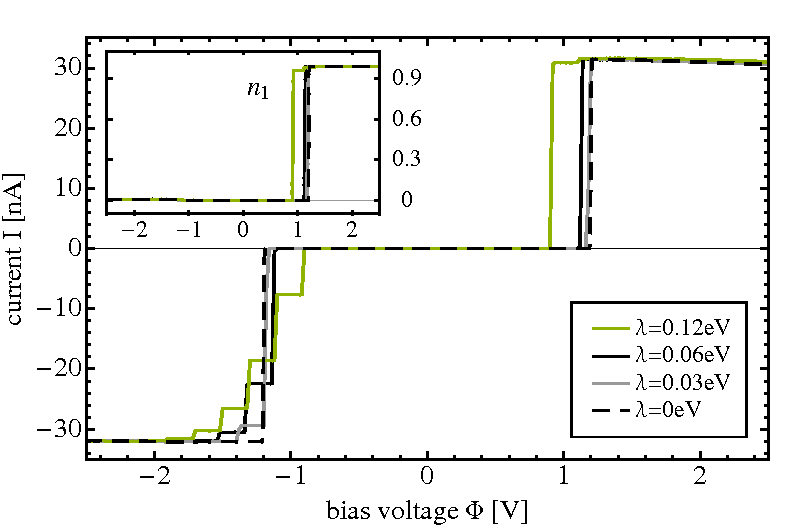
Fig. 4 shows the respective current-voltage characteristics for different electronic-vibrational couplings . If the vibration is kept in thermal equilibrium (Fig. 4a), the corresponding current is approximately anti-symmetric with respect to bias, . Significant deviations from this antisymmetry appear around the onset of the current at . This can be understood in terms of tunneling processes at the boundary between the molecule and the right lead, which represent the bottleneck for transport in this asymmetric transport scenario with . Recall that the probability for tunneling processes, where an electron with energy enters the bridge from the right lead, is , because the vibrational mode is essentially in its ground-state at K. An electron with energy entering the bridge from the right lead will cause a single excitation of the vibrational degree of freedom. Because it is treated as a reservoir degree of freedom, the vibration will exhibit fast relaxation such that the next electron traversing the junction finds the vibrational mode again in its ground-state. The respective transition probability is . Analogously, for electrons with energy it is . Thus, for negative bias voltages, where electrons flow preferentially from right to left, the current increases with relative step heights that are determined by the FC factors . In contrast to the findings in Sec. III.1.1 this is a quantitative statement. Thereby, the electronic state remains essentially unoccupied due to the asymmetry in the molecule-lead coupling, (cf. the inset of Fig. 4a). For positive biases, on the other hand, the molecular electronic state becomes almost fully occupied, , as soon as the electronic state enters the bias window. Successive resonant emission processes with respect to the left lead are thus Pauli-blocked and do not result in further steps in the current-voltage characteristics. The step at , however, is already as high as the one in the electronic current without vibronic coupling and thus displays no suppression due to electronic-vibrational coupling. This is due to the fact that a rather large number of resonant emission processes with respect to the right lead is already available at this bias voltage such that the sum of the respective FC factors approximately equals unity: . This requires the electronic level to be located well above the Fermi energy such that . Qualitative similar effects have been found previously in theoretical and experimental studies Braig and Flensberg (2003); Wu et al. (2004).
Including the current-induced excitation of the vibrational mode in full nonequilibrium gives qualitatively different results (cf. Fig. 4b). In particular, for large negative bias voltages the current does not approach the maximum value given by the electronic current (), but remains at a significantly lower absolute value. Thus, vibronic coupling results in a persistent rectification of the current, which appears not only in the vicinity of but for larger absolute values of the bias voltage as well. The comparison of Fig. 4a and Fig. 4b shows that this vibrational rectification is a pure nonequilibrium effect.
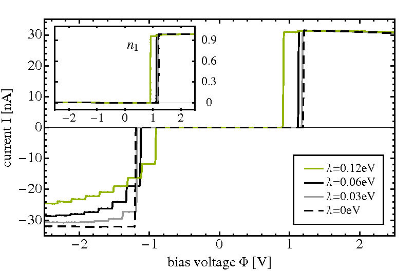
The respective vibrational excitation, depicted in Fig. 5 shows a similar asymmetry as the current. For negative bias voltage the level of vibrational excitation is much higher than for positive bias. We attribute this behavior to electron-hole pair creation processes with respect to the left lead (Fig. 2). Due to the strong coupling of the left lead to the electronic state at the molecular bridge, these processes provide the most important cooling mechanism in the junction. For negative bias voltages, however, the creation of an electron-hole pair in the left lead requires the absorption of many vibrational quanta ( in the resonant transport regime), which is rather unlikely. For positive bias voltages, on the contrary, such an electron-hole pair may be generated by absorbing much less vibrational quanta, which is much more probable and effectively cooling the vibrational mode. This results in a lower level of vibrational excitation for positive bias voltages, but also in a much higher level of vibrational excitation for negative bias voltages. The enhancement of vibrational rectification, which we observe in Fig. 4, is a result of this higher level of vibrational excitation (cf. the discussion at the end of Sec. III.1.1).
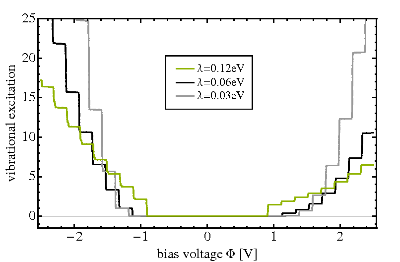
The phenomenon of vibrational rectification can be crucial for the interpretation of experimental data. In particular, it explains the disappearance or suppression of vibrational side-peaks for a specific direction of the bias voltage, although such peaks may be clearly visible for the opposite direction of the applied bias voltage. This phenomenon has been observed in a number of experiments Wu et al. (2004); Schulze et al. (2008); Ballmann et al. (2010).
III.1.3 Vibrationally induced Negative Differential Resistance (NDR)
In the model discussed in the previous section, the electronic state was located far away from the Fermi level of the system: . Thus the first step in the respective current-voltage characteristics involves a large number of emission and absorption processes that cannot be resolved separately. If the electronic state of such a molecular junction is located closer to the Fermi level, i.e. , every resonant emission (or absorption) process can be associated with a corresponding step in the transport characteristics. This is illustrated in Fig. 7, which represents the transport characteristics of a model system, where the energy of the molecular electronic state is eV ( eV). All other parameters are the same as in Sec. III.1.2.
We first consider results obtained with keeping the vibrational mode in thermal equilibrium (at K, i.e. essentially in its ground state), depicted by the blue and green lines in Fig. 7. Thereby, the blue line shows the current for positive bias voltages, , while the green line represents the current for negative bias voltages, . Due to the asymmetric molecule-lead coupling, , distinct resonances appear whenever a tunneling process with respect to the right lead becomes available. This results, e.g. for the blue line, in a resonance at . The corresponding transport processes are schematically shown in Fig. 6. Similarly, resonances appear at , with , and relative step heights in the current that are associated with the FC factors (as already outlined in Sec. III.1.2). Tunneling processes with respect to the right lead appear as steps in the green line as well, but at different bias voltages . As a consequence of the different position of the resonances, the number of tunneling processes with respect to the right lead differs for both lines at specific absolute values of the bias voltage, and therefore, the blue and the green line encircle small rectangles with a width of . The heights of these rectangles are given by the respective FC factors: (). Outside these rectangles, the blue and the green lines have the same absolute values, corresponding to an equal number of active transport channels with respect to the right lead.
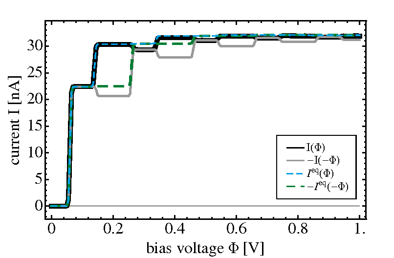
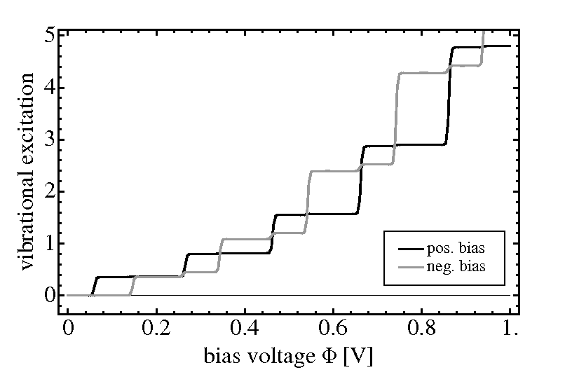
If the vibrational mode is allowed to develop its full current-induced nonequilibrium state, we obtain the solid black line for positive, and the solid gray line for negative biases. Again, the black and the gray line encircle rectangles. However, the heights of these are enlarged compared to the ones encircled by the blue and the green lines. This is related to the fact that the current represented by the gray line decreases at bias voltages , and is thus significantly smaller than the one represented by the green line, while the black and the blue line display essentially the same current values at these bias voltages. For (), when the black and the gray line start to overlap again, we observe a significant drop of the current represented by the black line. Interestingly, for both lines such negative differential resistance coincides with the steps in the associated vibrational excitation characteristics, which is shown in Fig. 7b. Here, the black line represents the vibrational excitation induced by the current for positive bias voltages, while the gray line depicts the one for negative bias voltages. For both polarities of the bias voltage, the vibrational excitation increases at exactly those values of , where electron-hole pair creation processes with respect to the left lead become blocked, i.e. for the black line at and for the gray line at , where . Recall that electron-hole pair creation with respect to the left lead is the most important cooling mechanism due to the asymmetry in the molecule-lead coupling, . Weakening this cooling mechanism results in larger vibrational excitation, and consequently in a reduced current or negative differential resistance (cf. Sec. III.1.1). As a result, a vibrational nonequilibrium state may not only induce rectification, as pointed out in Sec. III.1.2, but also negative differential resistance (NDR).
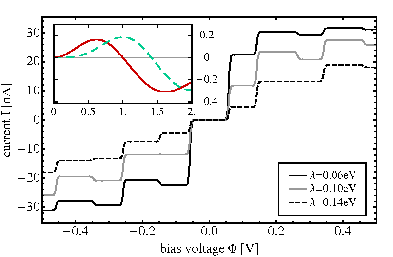
As is shown in Fig. 8, these features of negative differential resistance disappear one by one for stronger electronic-vibrational coupling . The first one at , which is closest to the Fermi level, disappears for Boese and Schoeller (2001); Zazunov et al. (2006). This can be understood, as before, by analysis of the tunneling processes with respect to the right lead. For bias voltages in the range there is only a single electronic tunneling process available, which is associated with a transition probability , because the vibration is not excited for this voltage. For smaller bias voltages in the range resonant emission processes with respect to the left lead result in a finite vibrational excitation. As a consequence, the vibrational mode can be deexcited by a resonant absorption process with respect to the right lead. The corresponding transition probability for tunneling from the right lead onto the bridge thus involves a superposition of and . For , such a superposition gives a smaller transition probability than the previous one with only , resulting in an overall smaller current (NDR). For , this transition probability becomes larger than . Consequently the current is also larger and the NDR at disappears. The red line in the inset of Fig. 8 shows the difference versus the electronic-vibrational coupling . The transition from a smaller to a higher transition probability is represented by the zero-crossing at . A similar analysis can be done for the second NDR feature at , which disappears for . This behavior is depicted by the dashed green line in the inset of Fig. 8, which represents the difference . The NDR features at higher bias voltages vanish for increasing electronic-vibrational coupling as well. However, in this case a detailed analysis of all the contributing processes is more involved.
Because this NDR effect is solely based on a vibrational nonequilibrium state, it is not exclusively restricted to asymmetric junctions. It is also found in symmetric junctions (see for example the gray line in Fig. 2 of Ref. Härtle et al., 2009). However, in symmetric junctions NDR is usually much less pronounced. This can be understood by the transport channels that become active, whenever electron-hole pair creation processes become blocked (e.g. the pair-creation processes in Fig. 2a are blocked as soon as the transport channel represented by Fig. 1c becomes active). In contrast to asymmetric junctions, all these transport channels contribute to the current and thus counteract the NDR mechanism that is induced by the higher level of vibrational excitation.
III.2 Transport through a molecular junction with two electronic states
In this section we study transport through a molecular junction with two electronic states. In addition to the phenomena discussed above for transport through a single electronic state, three new aspects need to be considered Härtle et al. (2009). First, in systems with multiple electronic states, the Hamiltonian in Eq. (4) comprises an electron-electron interaction term, which represents both Coulomb interactions and vibrationally induced electron-electron correlations. These electron-electron interactions result in a splitting of resonances Härtle et al. (2009) that depends on the specific population of the electronic states. For asymmetric junctions with a blocking state Hettler et al. (2002, 2003); Muralidharan and Datta (2007), they can induce strong NDR. While such NDR has been reported for specific values of the bias voltage , here we propose another model system with a centrally localized electronic state, where NDR due to electronic-vibrational coupling extends over a broad range of bias voltages. Secondly, coherences of the density matrix can play a significant role in transport through multiple electronic states Esposito and Galperin (2009); Esp . As is shown in appendix C, however, coherences are of importance only for asymmetrically coupled junctions with quasi-degenerate energy levels. For the systems considered in this Section, as in the preceding one, coherences of the density matrix can therefore be neglected. The third, and most intriguing aspect is that higher-lying electronic states facilitate the efficient absorption of vibrational energy Härtle et al. (2009); Romano et al. (2010). The role of these resonant absorption processes is elucidated in Sec. III.2.1 for symmetric molecular junctions, and in Sec. III.2.2 for asymmetric molecular junctions. This local cooling mechanism can be very efficient and crucial for the stability of the junction. Since closely-lying electronic states are typical for polyatomic molecules, this mechanism is expected to be of general importance in molecular junctions. It is also shown that repulsive Coulomb interactions may enhance this effect and thereby significantly improve the stability of a molecular junction (’Coulomb Cooling’).
|
III.2.1 Resonant absorption processes via a higher-lying electronic state in symmetric molecular junctions
We consider a model system with two electronic states, located at eV and at eV above the Fermi-level, respectively. The coupling strengths between the vibrational mode and the electronic states are given by eV and eV. In the results discussed in this section no Coulomb interactions are taken into account such that electron-electron interactions are induced by vibronic coupling only. As before, the left and the right lead are represented by semi-elliptic conduction bands. The respective level-width functions thus read
| (40) | |||||
where eV denote the coupling strengths of the left and the right lead to the th electronic state and eV determines the band-width in both leads.
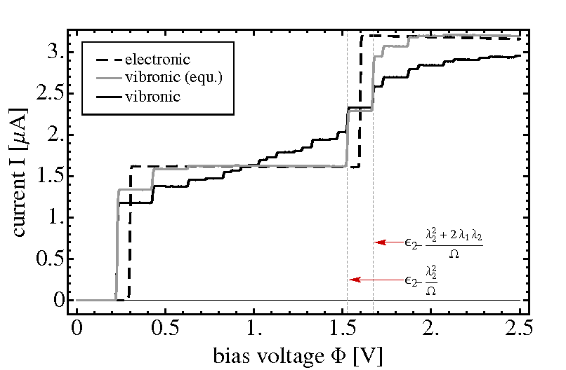
Current-voltage characteristics for this model molecular junction are shown in Fig. 10. Thereby, the dashed line represents results without electronic-vibrational coupling, . In this case, the two steps at and are associated with the onset of transport through the lower-lying electronic state at and the higher-lying electronic state at , respectively.
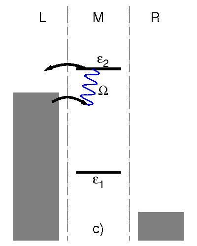
The solid lines depict the results including the coupling of the two electronic states to the vibrational mode. We first consider the results (solid gray line), where the vibrational mode is kept in thermal equilibrium ( K). The respective current-voltage characteristics exhibits two major steps that correspond to the polaron shifted levels . Vibrational side-steps with respect to these resonances can be distinguished similar to the results obtained for a single electronic state in Sec. III.1.1 (cf. Fig. 3). A more detailed analysis shows, however, that the current obtained for the two-state system is not just the sum of the current through the individual states. For example, the step at is just half as high as the one at . This behavior can be understood in terms of vibrationally induced electron-electron interaction, which is not present for a single electronic state. In this range of bias voltages, , electrons in the left lead have not enough energy to doubly occupy the molecular bridge. Since the low-lying electronic state is half occupied at this bias, , the step at is thus reduced by a factor of . Consequently, this step can be associated with the electronically excited state of the anion. If the bias exceeds the value , electrons from the left lead can overcome the additional charging energy . Hence, transport through the higher-lying electronic state becomes possible even though the low-lying electronic state is occupied, i.e. transport through the di-anionic state of the junction. As a result, the single step at , which is associated with the onset of transport through the second electronic state, is split into two steps at and . Vibrational side-steps with respect to the third, di-anionic resonance appear at bias voltages (). Note that since the vibrational coupling strengths and differ by sign. For the order of the steps associated with the excited state of the anion and the di-anionic state would be reversed. This scenario is described in Ref. Härtle et al., 2009.
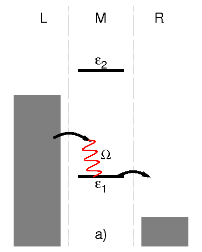
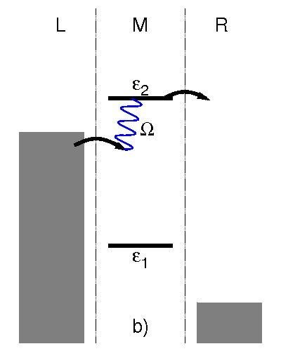
Next, we consider the results obtained with the vibrational mode treated in nonequilibrium (solid black lines of Figs. 10 and 11). The current-induced excitation of the vibrational mode changes the current-voltage characteristics profoundly. The most striking difference is the rise in current even before the second electronic state enters the bias window. This rise of the current is facilitated by the absorption of one or more vibrational quanta (see Fig. 9b for an example process). These resonant absorption processes appear at voltages and , and can take place only if the vibrational mode is in an excited state. Resonant emission processes with respect to the lower-lying electronic state (cf. Fig. 9a), however, are efficiently exciting the vibrational mode, and thus, provide the vibrational energy required for these processes (see Fig. 11). In addition, these resonant absorption processes result in a pronounced broadening of the resonances that are associated with the second electronic state. This leads to an almost Ohmic conductance characteristics, which is observed, e.g. in Fig. 10. This broadening complicates the spectroscopy of molecular levels in single-molecule junctions Boese and Schoeller (2001); Bergfield and Stafford (2009).
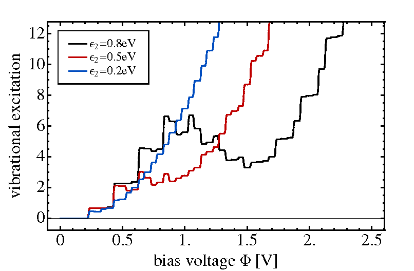
Resonant asorption processes due to higher-lying electronic states may have an even more profound effect on the vibrational excitation of the molecular junction, as shown in Fig. 11. For lower bias voltages, V, the vibrational excitation depicted by the black line (which was obtained for the same parameters as the - curves in Fig. 10) exhibits an increase similar to the case of a single electronic state (cf. Fig. 3b). For larger bias voltages, however, the vibrational excitation drops by more than 50%, before it starts to increase again for . This pronounced reduction of vibrational excitation is caused by absorption of vibrational energy via resonant absorption processes with respect to the higher-lying electronic state. Since the second rise of vibrational excitation is shifted by more than V, the molecular junction is effectively stabilized over a wide range of bias voltages Härtle et al. (2009); Romano et al. (2010). It is noted that a similar decrease of vibrational excitation with increasing bias voltage for a molecular junction has been observed in recent experiments by Ioffe et al. Ioffe et al. (2008).
The details of this stabilization or cooling mechanism depend on the energy gap between the higher- and lower lying electronic state. In particular, if the higher-lying state is located too close to the lower-lying state (see the solid red and blue line in Fig. 11), resonant emission processes with respect to both states become active at the same time, and no decrease of vibrational excitation is observed. Nevertheless, we expect this cooling mechanism to be relevant for most molecular junctions, because polyatomic molecules often exhibit multiple closely-lying electronic states.
III.2.2 Resonant absorption processes via a higher-lying electronic state in asymmetric molecular junctions
Resonant absorption processes with respect to a higher-lying electronic state involve not only electron transport processes (as in Fig. 9b) but also electron-hole pair creation processes (sketched in Fig. 9c). As was discussed in Sec. III.1, electron-hole pair creation plays an important role especially for asymmetric junctions, where the electronic states on the molecular bridge are coupled to the leads with different coupling strengths . There are eight topologically different scenarios for coupling two electronic states asymmetrically to a left and a right lead. Since all scenarios show similar effects, we focus in this section on the physically most relevant, where the two states of the model system introduced in Sec. III.2.1 are strongly coupled to the left, but weakly coupled to the right lead, eV. This coupling scenario describes, e.g., the experimental setup of a scanning tunneling microscope (STM) Stipe et al. (1998); Ogawa et al. (2007); Schulze et al. (2008); Pump et al. (2008).
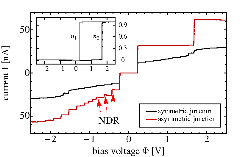
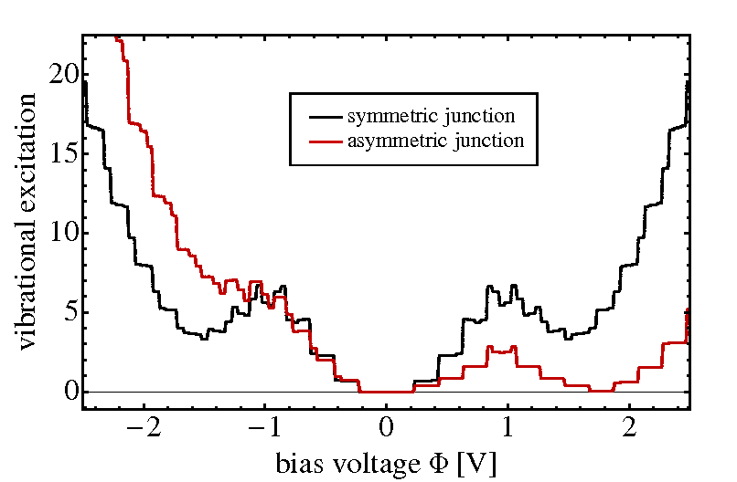
The corresponding current-voltage characteristics of this model is represented by the solid red line in Fig. 12a. For comparison, we also show the current of the corresponding symmetric model molecular junction with eV (solid black line) rescaled by a factor of . For positive bias voltages, the current shows only two steps at and . There is no splitting of the resonances associated with the higher-lying electronic state due to electron-electron interactions , since the low-lying electronic state is almost fully occupied, (cf. the inset of Fig. 12a), once it enters the bias window. Transport through the electronically excited state of the anion is thus not visible in the respective current-voltage characteristics (cf. the discussion in Sec. III.2.1). For negative biases, a multitude of vibronic resonances are seen resulting in the same rectifying behavior that was already discussed for a single electronic state in Sec. III.1.2. Small NDR features appear as well (highlighted by red arrows in Fig. 12), and can be related to the same mechanisms that was discussed in Sec. III.1.3. For positive bias voltages resonant absorption via the higher-lying electronic state does not significantly contribute to the current, since the vibrational mode is efficiently cooled by electron-hole pair creation processes with respect to the left lead via both electronic states (see, e.g., Fig. 9c). These processes are dominant in this regime due to the asymmetry in the molecule-lead couplings . For negative biases, however, electron-hole pair creation with respect to the left lead becomes inefficient due to the increased amount of vibrational energy required for these processes. Therefore, vibrational excitation increases faster for negative bias voltages than for a symmetrically coupled molecular junction. This asymmetry in vibrational excitation is depicted in Fig. 12b. Hence, in contrast to our previous findings for a symmetric junction, where the steps associated with the higher-lying electronic state are significantly broadened, we conclude that spectroscopy of molecular orbital energies may be more easily performed with a STM-like setup. Although resonant absorption processes are active, the mechanism of vibrational rectification restores the signatures of the individual molecular states.
III.2.3 Coulomb cooling
In this and the following subsection, we study the effects of repulsive Coulomb interactions () on vibrationally coupled electron transport through a molecular junction. We first consider the influence of these interactions on resonant absorption processes, and thus on the stability of such a junction. NDR effects that arise due to repulsive Coulomb interactions will be considered in Sec. III.2.4.
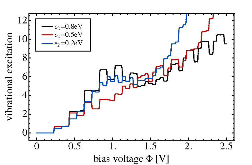
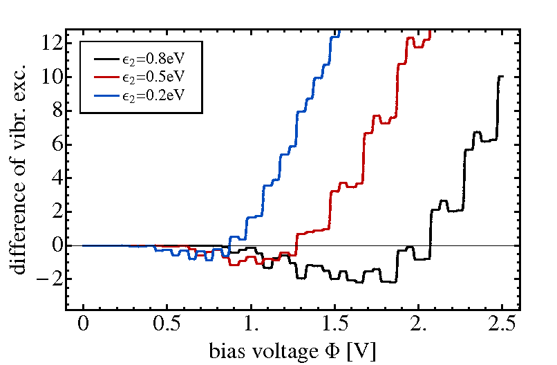
To this end, we employ the same two-state model system as in Sec. III.2.1, but add an additional charging energy of eV in the Hamiltonian, Eq. (II.1). This term accounts for repulsive Coulomb interactions between two electrons that are occupying the two electronic states of the junction. As a consequence, the resonance associated with the di-anionic state is shifted towards higher energies, from to . The resulting current-voltage characteristics (data not shown) shows the same features as analyzed in Sec. III.2.1. The major difference between the two scenarios is a shift of all steps associated with the di-anionic state towards higher bias voltages. As a result, the current increases more slowly in the resonant transport regime for . The respective vibrational excitation is shown in Fig. 13a. Thereby, the solid black, red and blue lines directly correspond to the lines in Fig. 11, which were obtained using the same model parameters but without Coulomb interaction. Since resonant absorption processes with respect to the di-anionic resonance are shifted to higher energies, the level of vibrational excitation increases faster than without repulsive Coulomb interactions for lower bias voltages. At higher bias voltages, however, these cooling processes are more efficient than without Coulomb interaction, as they require the absorption of less vibrational quanta. Moreover, they are not competing with absorption processes associated with the excited state of the anion. As a result, the vibrational excitation, which we obtain for large bias voltages including a repulsive Coulomb interaction eV, is reduced compared to that without additional electron-electron interactions. Thus, repulsive Coulomb interactions effectively stabilize a molecular junction. This cooling mechanism, here referred to as ’Coulomb Cooling’ is analyzed in more detail in Fig. 13b. The three different lines depict the difference in vibrational excitation, , obtained without, eV, and with Coulomb interaction, eV, respectively. The comparison shows that, except for small bias voltages, the Coulomb interactions lead to a strong reduction of the vibrational excitation and thus significant cooling not (d).
III.2.4 Negative Differential Resistance (NDR) induced by Coulomb interactions
In this last section, we study NDR effects induced by Coulomb interaction.
First, we consider junctions with asymmetric molecule-lead coupling. As we have already seen, asymmetries in the molecule-lead couplings can cause strong changes in the populations of the electronic levels. This is particularly important in the presence of Coulomb interactions, where they may result in pronounced NDR effects. To analyze this effect, we employ the same model parameters as in the previous section, except that the coupling of the higher-lying electronic state to the right lead is reduced to eV. This parameter regime is known as a blocking-state scenario Hettler et al. (2002, 2003); Muralidharan and Datta (2007). Furthermore, the energy of the higher-lying electronic state is chosen as eV. The current-voltage characteristics depicted in Fig. 14 shows that the combination of an asymmetry in the molecule-lead coupling and Coulomb interactions results in a significant NDR effect at a bias voltage of . Once the bias exceeds this value, , the second electronic state becomes almost fully occupied (see the inset of Fig. 14). This effectively blocks electron transport through the first electronic state, because an additional charging energy is required, and the respective current drastically decreases. If the bias is increased further , transport through the first electronic state can take place, although the second electronic state remains partially occupied. For negative bias voltages, however, the second electronic state leaves almost no traces in the current-voltage characteristics, as it remains unoccupied. As a consequence, NDR is not observed for this direction of the bias voltage.
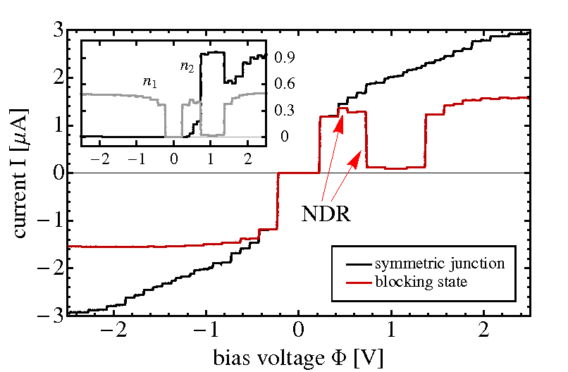
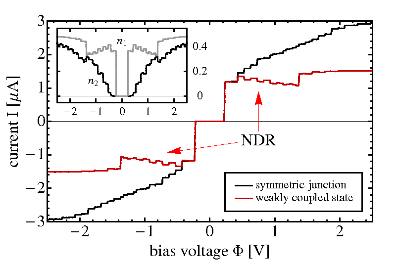
Another interesting mechanism for NDR is observed if the higher-lying electronic state of the molecular junction is weakly, but symmetrically coupled to both leads, eV. Such a state corresponds to a molecular orbital, which is stronger localized in the central part of the junction. The solid red line in Fig. 15 represents the corresponding current-voltage characteristics. In contrast to the NDR effect discussed above, the current decreases over a broad range of bias voltages, from to . Even for negative bias voltages, the absolute value of the current decreases from to . Hence, this mechanism for NDR is symmetric with respect to bias. The decrease in the current is accompanied by an increase in the population of the second electronic state, which, as before, is blocking the current through the first electronic state. The inset of Fig. 15 depicts the populations of both electronic states and shows the successive increase of . Thereby, the higher-lying state, due to resonant absorption processes, becomes occupied even before it enters the bias window. Increasing the bias voltage, the occupation number increases even further, as electronic tunneling processes and resonant emission processes become active. Overall, this increase takes place in small steps, resulting in an almost smooth current-voltage characteristics. Thus, transport through the lower-lying electronic state is not blocked in a single step, as for the NDR discussed before, but in a succession of several small steps, which results in a NDR feature that extends over a broad range of bias voltages.
IV Conclusion
In this paper we have studied vibrationally coupled electron transport in single-molecule junctions. The study was based on generic models for molecular junctions, which include electronic states on the molecular bridge that are vibrationally coupled and exhibit Coulomb interaction. The transport calculations employed a master equation approach, which is based on a second order expansion in the molecule-lead coupling. To the given order in the molecule-lead coupling, electronic-vibrational coupling and Hubbard-like electron-electron interactions are accurately described in this approach.
The results obtained for a series of models with increasing complexity, show a multitude of interesting transport phenomena, including vibrational excitation, rectification, negative differential resistance (NDR) as well as local cooling. While some of these phenomena have been observed or proposed before, the present analysis extends previous studies and allows a more detailed understanding of the underlying transport mechanisms. In particular, the analysis shows that many of the observed phenomena cannot be explained if only transport-induced processes (cf. Fig. 1) are taken into account, but also require the consideration of electron-hole pair creation processes (cf. Fig. 2). For example, these processes explain the increase of the step heights in vibrational excitation with increasing bias voltage and/or smaller electronic-vibrational coupling. Our results also show that in junctions with asymmetric molecule-lead coupling, electronic-vibrational interaction may result in a significant rectification of the current and the vibrational excitation, and even negative differential resistance. Both phenomena are accompanied by an highly excited nonequilibrium state of the vibrational mode. In these cases, electron-hole pair creation processes play a key-role. In contrast to transport-induced processes, they involve only one of the leads, and thus, effectively transfer the asymmetry of the molecule-lead coupling to the transport characteristics.
Extending previous work Härtle et al. (2009), we have also given a detailed analysis of the influence of multiple electronic states on vibronic effects in molecular junctions. The results show that resonant absorption processes involving higher-lying electronic states efficiently reduce the level of vibrational excitation and thus can stabilize a molecular junction over a broad range of bias voltages Härtle et al. (2009); Romano et al. (2010). In this context, we have shown that repulsive Coulomb interactions, which shift these resonant absorption processes to higher energies, can strongly enhance this cooling mechanism (’Coulomb Cooling’) and thus improve the stability of the junction. Repulsive Coulomb interaction may also cause pronounced negative differential resistance (NDR). While such NDR effects were reported before at specific values of the bias voltage Hettler et al. (2002, 2003); Muralidharan and Datta (2007), in the model proposed in this work NDR is caused by vibronic coupling and extents over a broad range of bias voltages. It should be noted that single-molecule junctions often exhibit a number of closely-lying electronic states, which are strongly coupled with the junctions vibrational degrees of freedom. Thus, it can be expected that the phenomena analyzed in this work are of relevance for many molecular junctions and may facilitate the understanding and interpretation of experimental data.
Acknowledgment: We thank M. Čížek, I. Pshenichnyuk, R. Volkovich and U. Peskin for helpful and inspiring discussions. The generous allocation of computing time by the Leibniz Rechenzentrum München (LRZ) as well as financial support from the Deutsche Forschungsgemeinschaft (DFG), the European Cooperation in Science and Technology (COST), the German-Israeli Foundation for Scientific Development (GIF), and the Fonds der Chemischen Industrie (FCI) are gratefully acknowledged. This work was carried out in the framework of the Cluster of Excellence ’Engineering of Advanced Materials’ of the DFG. R. H. gratefully acknowledges the hospitality in the group of M. Čížek in Prague and in the group of U. Peskin in Haifa.
Appendix A Master equation and current formula for a single electronic state
In this appendix, we give the explicit formulas for the master equation, Eq. (19), and the current, Eq. (26), for transport through a single electronic state coupled to a single vibrational mode. The density matrix of this scenario consists of elements, , corresponding to the two charge states and . In Eqs. (19) and (26) coherences between different charge states and are not coupled with the elements and that are diagonal with respect to the electronic degrees of freedom. Therefore, these elements do not need to be considered in the following. If we evaluate Eq. (19) in between the charge states and , we obtain
| (41) | |||
with
The corresponding component reads
| (42) | |||
From this set of algebraic equations, Eqs. (41) and (42), we determine the elements of the reduced density matrix, which are used to compute the current-voltage characteristics and the corresponding vibrational excitation of a single-molecule junction represented by a single electronic state (cf. Sec. II.3). Thereby, the current through a single electronic state is explicitly given by
In Eq. (A), principal value terms, as for the computation of the reduced density matrix, are disregarded.
Appendix B Master equation and current formula for two electronic states
In this appendix, we give the explicit formulas for the master equation, Eq. (19),
and the current, Eq. (26), for transport through two electronic states
coupled to a single vibrational mode. Similar to the scenario with one electronic state,
coherences between different charge states are not considered, as they are
not coupled with the remaining elements of the density matrix. Thus, we are left with
the computation of six different density matrix elements: ,
(), and ,
where we employ the states , ,
, and . For notational convenience
we introduce indices , defined by and .
Accordingly, we evaluate Eq. (19) between the states
and
with
Evaluation of Eq. (19) between the states and , where , gives
with
The respective component reads
As for a single electronic state, this set of algebraic equations determines the density matrix describing transport through two electronic states. The current through two electronic states is explicitly given by
Thereby, principal value terms, as for the computation of the reduced density matrix, are disregarded.
Appendix C Effects of electronic and vibrational coherences
None of the results that we have discussed in Sec. III are significantly influenced by electronic or vibrational coherences of the reduced density matrix. This is due to the specific model parameters used. The respective eigenstates ( or ) do not exhibit any (quasi-)degeneracies. However, in realistic systems the molecular states can show some (quasi-)degeneracy, and therefore, we investigate the effect of such coherences in this section.
For a single electronic state and a single harmonic mode, the molecular states are quasi-degenerate, if the broadening of the levels exceeds the level spacing set by the frequency . But in this regime, where , a perturbative expansion in may not be appropriate. Therefore, we start our discussion with a model system comprising two electronic states. We expect coherences to play a major role for degenerate or quasi-degenerate electronic states, i.e. for Harbola et al. (2006). As long as the couplings of the two quasi-degenerate electronic states to the leads are symmetric, we find the same results with and without coherences. This can be understood by inspection of Eqs. (B) and (B). For symmetric junctions with and with , where holds, Eqs. (B) and (B) have almost the same structure. The only difference, in that case, is the sign by which coherences enter these equations. For that reason, the coherences cancel in these equations and, as a result, do not influence the respective transport characteristics. Only for non-symmetric couplings to the leads we find a significant effect of coherences on the transport characteristics of this system. The most pronounced effect appears, if one of the molecule-lead couplings differs by sign e.g. for and if the two states are degenerate . This specific model system can be identically transformed to two orthogonal states, which are not interacting with each other and which are coupled to one of the leads only (either left or right). Hence, the current through this system is zero for any bias voltage Holleitner et al. (2001); Kubala and König (2002). However, if we disregard electronic coherences, we obtain a finite current that corresponds to the current of two states symmetrically coupled to the leads. Thus, for quasi-degenerate electronic states that are non-symmetrically coupled to the leads, electronic coherences must be accounted for to obtain physically correct results.
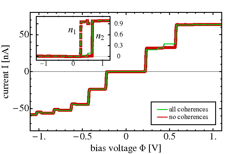
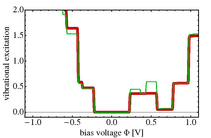
The role of vibrational coherences can be studied employing a similar model system with two electronic states and energies that differ by the frequency of the vibrational mode, i.e. . Systems with and display similar but less pronounced effects, as the impact of coherences decreases the further away they are located from the diagonal of the density matrix Harbola et al. (2006). Again, for totally symmetric molecule-lead couplings , we do not observe a significant influence of coherences. Only for asymmetric transport scenarios we find coherences to play a significant role for the transport characteristics. In Fig. 16 we present the current-voltage characteristics and the vibrational excitation for the asymmetric model system introduced in Sec. III.2.2 with the energy of the higher-lying state adjusted to eV. Thereby, the red line represents a calculation where all coherences are disregarded, while the green line represents the results for a calculation where all coherences are taken into account. Only in the vicinity to vibrational coherences influence the current-voltage characteristics. For positive bias voltages, the first step in the green line is diminished, since coherences result in a small population of the second higher-lying electronic state (cf. the inset of Fig. 16a), which is thus blocking transport through the low-lying electronic state due to vibrationally induced repulsive electron-electron interactions . This blocking is lifted again for higher bias voltages, when electrons in the left lead have enough energy, i.e. more than . Vibrational excitation is enhanced as well, because there is an additional resonant emission process for tunneling from the higher-lying electronic state to the right lead. Similarly, coherences result in a somewhat larger current for bias voltages , where the higher-lying electronic state enters the bias window. Again, the population of the second electronic state is increased by vibrational coherences, although repulsive electron-electron interactions block the population of, and similarly, transport through this state. Coherences soften this blocking, resulting in a larger current and vibrational excitation.
We expect systems with more than one vibrational degree of freedom to display gradually more quasi-degenerate levels, and hence, coherences to play a gradually more important role. Moreover for anharmonic potentials that are describing e.g. molecular motors Psh , coherences are crucial to characterize the actual motion of the molecule.
References
- Nitzan (2001) A. Nitzan, Annu. Rev. Phys. Chem. 52, 681 (2001).
- Cuniberti et al. (2005) G. Cuniberti, G. Fagas, and K. Richter, Introducing Molecular Electronics (Springer, Heidelberg, 2005).
- Selzer and Allara (2006) Y. Selzer and D. L. Allara, Annu. Rev. Phys. Chem. 57, 593 (2006).
- Venkataraman et al. (2006) L. Venkataraman, J. E. Klare, C. Nuckolls, M. S. Hybertsen, and M. L. Steigerwald, Nature 442, 904 (2006).
- Chen et al. (2007) F. Chen, J. Hihath, Z. Huang, X. Li, and N. J. Tao, Annu. Rev. Phys. Chem. 58, 535 (2007).
- Galperin et al. (2008) M. Galperin, M. A. Ratner, A. Nitzan, and A. Troisi, Science 319, 1056 (2008).
- van der Molen and Liljeroth (2010) S. J. van der Molen and P. Liljeroth, J. Phys.: Condens. Matter 22, 133001 (2010).
- Cuevas and Scheer (2010) J. C. Cuevas and E. Scheer, Molecular Electronics: An Introduction To Theory And Experiment (World Scientific, Singapore, 2010).
- Tao (2006) N. J. Tao, Nat. Nano. 1, 173 (2006).
- Elbing et al. (2005) M. Elbing, R. Ochs, M. Koentopp, M. Fischer, C. von Hänisch, F. Weigend, F. Evers, H. Weber, and M. Mayor, Proc. Natl. Acad. Sci. USA 102, 8815 (2005).
- Reed et al. (1997) M. A. Reed, C. Zhou, C. J. Muller, T. P. Burgin, and J. M. Tour, Science 278, 252 (1997).
- Reichert et al. (2002) J. Reichert, R. Ochs, D. Beckmann, H. B. Weber, M. Mayor, and H. v. Lohneysen, Phys. Rev. Lett. 88, 176804 (2002).
- Smit et al. (2002) R. Smit, Y. Noat, C. Untiedt, N. Lang, M. van Hemert, and J. van Ruitenbeek, Nature (London) 419, 906 (2002).
- Böhler et al. (2004) T. Böhler, J. Grebing, A. Mayer-Gindner, H. von Löhneysen, and E. Scheer, Nanotechnology 15, 465 (2004).
- Martin et al. (2010) C. A. Martin, J. M. van Ruitenbeek, and H. S. J. van de Zandt, Nanotechnology 21, 265201 (2010).
- Yu et al. (2004) L. H. Yu, Z. K. Keane, J. W. Ciszek, L. Cheng, M. P. Stewart, J. M. Tour, and D. Natelson, Phys. Rev. Lett. 93, 266802 (2004).
- Sapmaz et al. (2005) S. Sapmaz, P. Jarillo-Herrero, Y. M. Blanter, and H. S. J. van der Zant, New J. Phys. 7, 243 (2005).
- Sapmaz et al. (2006) S. Sapmaz, P. Jarillo-Herrero, Y. M. Blanter, C. Dekker, and H. S. J. van der Zant, Phys. Rev. Lett. 96, 026801 (2006).
- de Leon et al. (2008) N. P. de Leon, W. Liang, Q. Gu, and H. Park, Nano Lett. 8, 2963 (2008).
- Hüttel et al. (2009) A. K. Hüttel, B. Witkamp, M. Leijnse, M. R. Wegewijs, and H. S. J. van der Zant, Phys. Rev. Lett. 102, 225501 (2009).
- Osorio et al. (2010) E. A. Osorio, M. Ruben, J. S. Seldenthuis, J. M. Lehn, and H. S. J. van der Zant, Small 6, 174 (2010).
- Stipe et al. (1998) B. Stipe, M. A. Rezai, and W. Ho, Science 280, 1732 (1998).
- Wu et al. (2004) S. W. Wu, G. V. Nazin, X. Chen, X. H. Qiu, and W. Ho, Phys. Rev. Lett. 93, 236802 (2004).
- Ogawa et al. (2007) N. Ogawa, G. Mikaelian, and W. Ho, Phys. Rev. Lett. 98, 166103 (2007).
- Schulze et al. (2008) G. Schulze, K. J. Franke, A. Gagliardi, G. Romano, C. S. Lin, A. Da Rosa, T. A. Niehaus, T. Frauenheim, A. Di Carlo, A. Pecchia, et al., Phys. Rev. Lett. 100, 136801 (2008).
- Pump et al. (2008) F. Pump, R. Temirov, O. Neucheva, S. Soubatch, S. Tautz, M. Rohlfing, and G. Cuniberti, Appl. Phys. A 93, 335 (2008).
- Hihath et al. (2010) J. Hihath, C. Bruot, and N. Tao, ACS Nano 4, 3823 (2010).
- Mayor (2009) M. Mayor, Angew. Chem. Int. Ed. 48, 5583 (2009).
- Chen et al. (2009) X. Chen, A. B. Braunschweig, M. J. Wiester, S. Yeganeh, M. A. Ratner, and C. A. Mirkin, Angew. Chem. 121, 5280 (2009).
- Song et al. (2009) H. Song, Y. Kim, Y. H. Jang, H. Jeong, M. A. Reed, and T. Lee, Nature 462, 1039 (2009).
- Yeganeh et al. (2007) S. Yeganeh, M. Galperin, and M. A. Ratner, J. Am. Chem. Soc. 129, 13313 (2007).
- Lörtscher et al. (2006) E. Lörtscher, J. W. Ciszek, J. Tour, and H. Riel, Small 2, 973 (2006).
- Choi et al. (2006) B. Y. Choi, S. J. Kahng, S. Kim, H. Kim, H. W. Kim, Y. J. Song, J. Ihm, and Y. Kuk, Phys. Rev. Lett. 96, 156106 (2006).
- Meded et al. (2009) V. Meded, A. Bagrets, A. Arnold, and F. Evers, Small 5, 2218 (2009).
- Benesch et al. (2009) C. Benesch, M. F. Rode, M. Cizek, R. Härtle, O. Rubio-Pons, M. Thoss, and A. L. Sobolewski, J. Phys. Chem. C 113, 10315 (2009).
- Diez-Perez et al. (2009) I. Diez-Perez, J. Hihath, Y. Lee, L. Yu, L. Adamska, M. A. Kozhushner, I. I. Oleynik, and N. Tao, Nature Chemistry 1, 635 (2009).
- Gaudioso et al. (2000) J. Gaudioso, L. J. Lauhon, and W. Ho, Phys. Rev. Lett. 85, 1918 (2000).
- LeRoy et al. (2004) B. J. LeRoy, S. G. Lemay, J. Kong, and C. Dekker, Nature 432, 371 (2004).
- Pop et al. (2005) E. Pop, D. Mann, J. Cao, Q. Wang, K. Goodson, and H. Dai, Phys. Rev. Lett. 95, 155505 (2005).
- Härtle et al. (2008) R. Härtle, C. Benesch, and M. Thoss, Phys. Rev. B 77, 205314 (2008).
- Härtle et al. (2009) R. Härtle, C. Benesch, and M. Thoss, Phys. Rev. Lett. 102, 146801 (2009).
- Romano et al. (2010) G. Romano, A. Gagliardi, A. Pecchia, and A. Di Carlo, Phys. Rev. B 81, 115438 (2010).
- Härtle et al. (2010) R. Härtle, R. Volkovich, M. Thoss, and U. Peskin, J. Chem. Phys. 133, 081102 (2010).
- Reed et al. (1988) M. A. Reed, J. N. Randall, R. J. Aggarwal, R. J. Matyi, T. M. Moore, and A. E. Wetsel, Phys. Rev. Lett. 60, 535 (1988).
- Muralidharan and Datta (2007) B. Muralidharan and S. Datta, Phys. Rev. B 76, 035432 (2007).
- Holleitner et al. (2001) A. W. Holleitner, C. R. Decker, H. Qin, K. Eberl, and R. H. Blick, Phys. Rev. Lett. 87, 256802 (2001).
- Kubala and König (2002) B. Kubala and J. König, Phys. Rev. B 65, 245301 (2002).
- Pasupathy et al. (2005) A. N. Pasupathy, J. Park, C. Chang, A. V. Soldatov, S. Lebedkin, R. C. Bialczak, J. E. Grose, L. A. K. Donev, J. P. Sethna, D. C. Ralph, et al., Nano Lett. 5, 203 (2005).
- Thijssen et al. (2006) W. H. A. Thijssen, D. Djukic, A. F. Otte, R. H. Bremmer, and J. M. van Ruitenbeek, Phys. Rev. Lett. 97, 226806 (2006).
- Parks et al. (2007) J. J. Parks, A. R. Champagne, G. R. Hutchison, S. Flores-Torres, H. D. Abruna, and D. C. Ralph, Phys. Rev. Lett. 99, 026601 (2007).
- Böhler et al. (2007) T. Böhler, A. Edtbauer, and E. Scheer, Phys. Rev. B 76, 125432 (2007).
- Ballmann et al. (2010) S. Ballmann, W. Hieringer, D. Secker, Q. Zheng, J. A. Gladysz, A. Görling, and H. B. Weber, Chem. Phys. Chem. 11, 2256 (2010).
- Jewell et al. (2010) A. D. Jewell, H. L. Tierney, A. E. Baber, E. V. Iski, M. M. Laha, and E. C. H. Sykes, J. Phys.: Condens. Matter 22, 264006 (2010).
- Huang et al. (2006) Z. Huang, B. Xu, Y. Chen, M. Di Ventra, and N. Tao, Nano Lett. 6, 1240 (2006).
- Ward et al. (2008) D. R. Ward, N. J. Halas, J. W. Ciszek, J. M. Tour, Y. Wu, P. Nordlander, and D. Natelson, Nano Lett. 8, 919 (2008).
- Ioffe et al. (2008) Z. Ioffe, T. Shamai, A. Ophir, G. Noy, I. Yutsis, K. Kfir, O. Cheshnovsky, and Y. Selzer, Nat. Nano. 3, 727 (2008).
- Cizek et al. (2004) M. Cizek, M. Thoss, and W. Domcke, Phys. Rev. B 70, 125406 (2004).
- Caspary Toroker and Peskin (2007) M. Caspary Toroker and U. Peskin, J. Chem. Phys. 127, 154706 (2007).
- Zimbovskaya and Kuklja (2009) N. A. Zimbovskaya and M. M. Kuklja, J. Chem. Phys. 131, 114703 (2009).
- Jorn and Seidemann (2009) R. Jorn and T. Seidemann, J. Chem. Phys. 131, 244114 (2009).
- Flensberg (2003) K. Flensberg, Phys. Rev. B 68, 205323 (2003).
- Mitra et al. (2004) A. Mitra, I. Aleiner, and A. J. Millis, Phys. Rev. B 69, 245302 (2004).
- Galperin et al. (2006a) M. Galperin, A. Nitzan, and M. A. Ratner, Phys. Rev. B 73, 045314 (2006a).
- Ryndyk et al. (2006) D. A. Ryndyk, M. Hartung, and G. Cuniberti, Phys. Rev. B 73, 045420 (2006).
- Frederiksen et al. (2007) T. Frederiksen, N. Lorente, M. Paulsson, and M. Brandbyge, Phys. Rev. B 75, 235441 (2007).
- Tahir and MacKinnon (2008) M. Tahir and A. MacKinnon, Phys. Rev. B 77, 224305 (2008).
- Bergfield and Stafford (2009) J. P. Bergfield and C. A. Stafford, Phys. Rev. B 79, 245125 (2009).
- Mühlbacher and Rabani (2008) L. Mühlbacher and E. Rabani, Phys. Rev. Lett. 100, 176403 (2008).
- Weiss et al. (2008) S. Weiss, J. Eckel, M. Thorwart, and R. Egger, Phys. Rev. B 77, 195316 (2008).
- Wang and Thoss (2009) H. Wang and M. Thoss, J. Chem. Phys. 131, 024114 (2009).
- Pedersen and Wacker (2005) J. N. Pedersen and A. Wacker, Phys. Rev. B 72, 195330 (2005).
- Harbola et al. (2006) U. Harbola, M. Esposito, and S. Mukamel, Phys. Rev. B 74, 235309 (2006).
- Zazunov et al. (2006) A. Zazunov, D. Feinberg, and T. Martin, Phys. Rev. B 73, 115405 (2006).
- Siddiqui et al. (2007) L. Siddiqui, A. W. Ghosh, and S. Datta, Phys. Rev. B 76, 085433 (2007).
- Timm (2008) C. Timm, Phys. Rev. B 77, 195416 (2008).
- May and Kühn (2008a) V. May and O. Kühn, Phys. Rev. B 77, 115439 (2008a).
- May and Kühn (2008b) V. May and O. Kühn, Phys. Rev. B 77, 115440 (2008b).
- Leijnse and Wegewijs (2008) M. Leijnse and M. R. Wegewijs, Phys. Rev. B 78, 235424 (2008).
- Esposito and Galperin (2009) M. Esposito and M. Galperin, Phys. Rev. B 79, 205303 (2009).
- (80) M. Esposito and M. Galperin, arXiv:1004.2533 (2010).
- Lehmann et al. (2004) J. Lehmann, S. Kohler, V. May, and P. Hänggi, J. Chem. Phys. 121, 2278 (2004).
- May (2002) V. May, Phys. Rev. B 66, 245411 (2002).
- Lüffe et al. (2008) M. C. Lüffe, J. Koch, and F. von Oppen, Phys. Rev. B 77, 125306 (2008).
- König et al. (1996) J. König, H. Schoeller, and G. Schön, Phys. Rev. Lett. 76, 1715 (1996).
- Paaske and Flensberg (2005) J. Paaske and K. Flensberg, Phys. Rev. Lett. 94, 176801 (2005).
- Galperin et al. (2007) M. Galperin, A. Nitzan, and M. A. Ratner, Phys. Rev. B 76, 035301 (2007).
- Leijnse et al. (2009) M. Leijnse, M. R. Wegewijs, and M. H. Hettler, Phys. Rev. Lett. 103, 156803 (2009).
- Han (2010) J. E. Han, Phys. Rev. B 81, 113106 (2010).
- Persson and Ueba (2002) B. N. J. Persson and H. Ueba, Surface Science 502-503, 18 (2002).
- Mii et al. (2002) T. Mii, S. Tikhodeev, and H. Ueba, Surface Science 502-503, 26 (2002).
- not (a) A different mechanism for electron-hole pair creation, which involves an electronically excited state of the junction instead of a vibrationally excited one, is discussed e.g. in Refs. Galperin et al., 2006b; Fainberg et al., 2007.
- Boese and Schoeller (2001) D. Boese and H. Schoeller, Europhys. Lett. 54, 668 (2001).
- Koch and von Oppen (2005) J. Koch and F. von Oppen, Phys. Rev. B 72, 113308 (2005).
- Hettler et al. (2002) M. H. Hettler, H. Schoeller, and W. Wenzel, Europhys. Lett. 57, 571 (2002).
- Hettler et al. (2003) M. H. Hettler, W. Wenzel, M. R. Wegewijs, and H. Schoeller, Phys. Rev. Lett. 90, 076805 (2003).
- Benesch et al. (2008) C. Benesch, M. Cizek, J. Klimes, M. Thoss, and W. Domcke, J. Phys. Chem. C 112, 9880 (2008).
- Cederbaum and Domcke (1974) L. Cederbaum and W. Domcke, J. Chem. Phys. 60, 7 (1974).
- Mahan (1981) G. D. Mahan, Many-Particle Physics (Plenum Press, 1981).
- Blum (1981) K. Blum, Density Matrix Theory and Applications (Plenum Press, New York, 1981).
- Louisell (1973) W. H. Louisell, Quantum Statistical Properties of Radiation (Wiley, New York, 1973).
- Davidson (1976) E. R. Davidson, Reduced Density Matrices in Quantum Chemistry (Academic Press, London, 1976).
- Weiss (1993) U. Weiss, Quantum Dissipative Systems (World Scientific, Singapore, 1993).
- May and Kühn (2004) V. May and O. Kühn, Charge and Energy Transfer Dynamics in Molecular Systems (Wiley-VCH, Weinheim, 2004).
- Nakajima (1958) S. Nakajima, Prog. Theor. Phys. 20, 948 (1958).
- Zwanzig (1960) R. Zwanzig, J. Chem. Phys. 33, 1338 (1960).
- Egorova et al. (2003) D. Egorova, M. Thoss, W. Domcke, and H. Wang, J. Chem. Phys. 119, 2761 (2003).
- Volkovich et al. (2008) R. Volkovich, M. Caspary Toroker, and U. Peskin, J. Chem. Phys. 129, 034501 (2008).
- not (b) For an account of non-Markovian effects see also Refs. Petrov and Hänggi, 2001; Flindt et al., 2008; Zedler et al., 2009; Rivas et al., 2010.
- Redfield (1965) A. G. Redfield, Adv. Magn. Reson. 1, 1 (1965).
- Koch et al. (2006) J. Koch, M. Semmelhack, F. von Oppen, and A. Nitzan, Phys. Rev. B 73, 155306 (2006).
- Braig and Flensberg (2003) S. Braig and K. Flensberg, Phys. Rev. B 68, 205324 (2003).
- Shen et al. (2007) X. Y. Shen, B. Dong, X. L. Lei, and N. J. M. Horing, Phys. Rev. B 76, 115308 (2007).
- Pascual et al. (2003) J. I. Pascual, N. Lorente, Z. Song, H. Conrad, and H. P. Rust, Nature 423, 525 (2003).
- Eigler and Schweizer (1991) D. M. Eigler and E. K. Schweizer, Nature 344, 524 (1991).
- Eigler et al. (1991) D. M. Eigler, C. P. Lutz, and W. E. Rudge, Nature 352, 600 (1991).
- Gao et al. (1992) S. Gao, M. Persson, and B. Lundqvist, Solid State Communications 84, 271 (1992).
- not (c) In contrast to electron-hole pair creation processes, the transport induced processes, absorption (Fig. 1b) and emission processes (Figs. 1a and 1c), remain active for large biases. Indeed, the number of possible transport processes increases with increasing bias voltage.
- not (d) We like to note that even stronger Coulomb interactions result in a splitting of the di-anionic resonance, which thus appears at two different bias voltages: and .
- (119) I. Pshenichnyuk and M. Cizek, arXiv:1008.0035 (2010).
- Galperin et al. (2006b) M. Galperin, A. Nitzan, and M. A. Ratner, Phys. Rev. Lett. 96, 166803 (2006b).
- Fainberg et al. (2007) B. D. Fainberg, M. Jouravlev, and A. Nitzan, Phys. Rev. B 76, 245329 (2007).
- Petrov and Hänggi (2001) E. G. Petrov and P. Hänggi, Phys. Rev. Lett. 86, 2862 (2001).
- Flindt et al. (2008) C. Flindt, T. Novotný, A. Braggio, M. Sassetti, and A.-P. Jauho, Phys. Rev. Lett. 100, 150601 (2008).
- Zedler et al. (2009) P. Zedler, G. Schaller, G. Kiesslich, C. Emary, and T. Brandes, Phys. Rev. B 80, 045309 (2009).
- Rivas et al. (2010) A. Rivas, S. F. Huelga, and M. B. Plenio, Phys. Rev. Lett. 105, 050403 (2010).