Bragg polaritons: Strong coupling and amplification in an unfolded microcavity
Abstract
Periodic incorporation of quantum wells inside a one–dimensional Bragg structure is shown to enhance coherent coupling of excitons to the electromagnetic Bloch waves. We demonstrate strong coupling of quantum well excitons to photonic crystal Bragg modes at the edge of the photonic bandgap, which gives rise to mixed Bragg polariton eigenstates. The resulting Bragg polariton branches are in good agreement with the theory and allow demonstration of Bragg polariton parametric amplification.
pacs:
71.35.-y, 78.67.Pt, 71.36.+cSemiconductor microcavities in the strong coupling regime weisbuch offer an ideal testbed for harnessing light–matter interactions at nanometer scale. In addition, they appear to be highly suitable systems for realization of a new generation of optoelectronic devices tsintzos1 ; liew of unprecedented efficiency christmann operating on new physical principles such as, e.g., polariton lasing christopoulos which requires no population inversion imamoglu ; deng . However, the strength of light–matter coupling in GaAs–based microcavities, normally quantified in units of Rabi energy, is limited by the number of quantum wells (QWs) that can be integrated at the antinodes of the electric field inside the microcavity savona . Conventional approaches to enhance Rabi splitting required for high temperature operation of these devices include increasing cavity thickness to incorporate larger number of QWs at the expense of growing mode volume pelekanos . Additionally, to compensate for the undesired penetration of the electric field into the mirrors, insertion of extra QWs in the first periods of the Bragg reflector where electric field retains its strength, has also been implemented bloch .
In recent years the Bragg polariton concept has attracted increasing attention, as a new tool for tailoring light–matter coupling. Several recent reports explore the possibility of creating Bragg polaritons by incorporation of excitonic resonances periodically throughout a photonic crystal. Both confined excitons inside a QW faure as well as large oscillator strength bulk excitons in materials such as ZnO have been consideredbiancalana . However, the relatively small refractive index contrasts of the considered structures impose limitations on the width of the PBG, hindering clear separation of Bragg polariton branches goldberg . Similarly, exciton-Bragg mode hybridization has also been reported in a CdTe microcavity with exciton coupling occurring to both cavity and PBG leaky modes owing to the very large exciton binding energies of CdTe systemsrichard .
In this Letter we use a periodic Bragg structure referred to as unfolded microcavity with well defined PBG and sharp Bragg resonances, to experimentally demonstrate strong coherent coupling between Bragg photons and InGaAs QW excitons. The new eigenmodes of the system exhibit characteristic anticrossing behavior and are an admixture of excitons and Bragg photons. The corresponding Bragg polariton branches are shown to be in excellent agreement with the theoretical models.
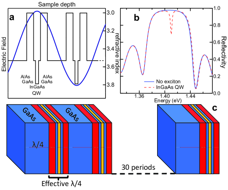
Our structure is an optimized unfolded microcavity in which QWs are incorporated into a Bragg mirror stack. The sample shown in Figure 1(c) consists of a stack of quarter wavelength thick alternating high refractive index () GaAs layer and of a smaller effective refractive index () pseudo-layer AlAs/GaAs/InGaAs/GaAs/AlAs whose effective optical thickness is . The 10nm wide In0.1Ga0.9As QWs are placed symmetrically inside the pseudo-layer at the antinodes of the electric field as shown in Figure 1(a). The sample is mounted inside a He cryostat and the temperature is maintained at 32K.
In Figure 1(b) reflectivity spectra of the pseudo–Bragg stack without excitonic absorption calculated using standard transfer matrix technique are presented showing 81meV (50nm) wide PBG centered at 1.418eV (875nm). The maximum reflectivity at the center of the PBG for a 30–period stack sample exceeds . Clear indication of the existence of the Bragg polariton mode is seen in Figure 1(b) (solid red line) when “switching on” the excitonic absorption in the transfer matrix model, which results in a sharp mode inside the otherwise forbidden PBG. We experimentally probe Bragg polariton branches using white light reflectivity measurements. Tuning of the Bragg mode, located at the high energy side of the PBG through the excitonic resonance is achieved by scanning the reflectivity spot across the sample at normal incidence and exploiting the built–in wedge, intentionally introduced during the sample growth.
In Figure 2(a) a series of reflectivity spectra taken at different positions across the sample in the order of increasing layer thickness is presented. Increasing layer thickness results in the shifting of the whole PBG to lower energies with the corresponding tuning of the Bragg resonance. It is convenient to define as detuning , the difference in energy between the edge of the PBG and the exciton resonance. As seen in Figure 2(a), for positive detuning conditions a sharp exciton–like resonance is observed within the PBG while the Bragg mode appears on the high energy side of the PBG. With decreasing detuning the Bragg mode is continuously tuned across the excitonic resonance exhibiting a characteristic anticrossing behavior at zero detuning until it reappears on the other side of the excitonic resonance. Such anticrossing behavior with a Rabi splitting of 9.3 meV is a direct manifestation of the strong coupling regime which gives rise to the new eigenmodes of the system, namely Bragg polaritons, part light part matter quasiparticles. Persistence of strong coupling regime in this sample up to a temperature of 100K has been experimentally verified.
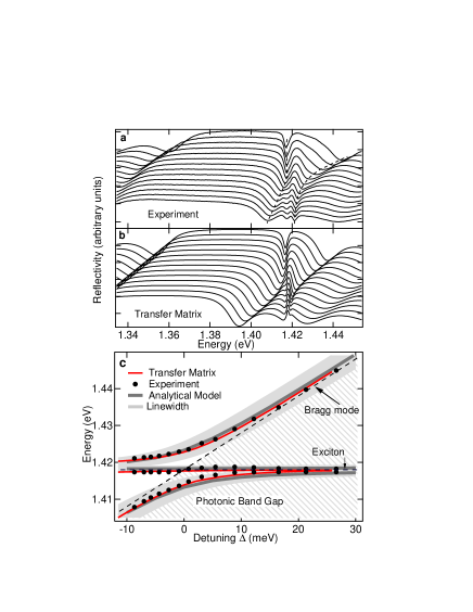
Notably, in addition to the two anticrossing branches, a third dispersionless feature is also observed between them. In order to shed light on the origin of this dispersionless branch, we perform transfer matrix calculations of the normal incidence reflectivity spectra with increasing layer thickness. In Figure 2(b), the corresponding modeled reflectivity spectra are presented, showing excellent agreement with the experimental data and reproducing the anticrossing behavior and the existence of the middle branch. The good agreement is clearly confirmed when extracting both experimental (black circles) and calculated (solid line) reflectivity dip positions for different exciton–Bragg mode detunings, as shown in Figure 2(c). The position and non–dispersive nature of the middle branch suggests the presence of uncoupled excitonic states in the system. In order to confirm this hypothesis we developed a coupled harmonic oscillator model to fit our Bragg polariton branches vardeny ; panzarini ; ivchenko .
We note that our 30–period Bragg structure can be approximated by an infinite periodic medium characterized by an effective refractive index , in which both photonic and excitonic states are represented using Bloch waves. We denote the bare uncoupled photonic modes propagating in positive and negative directions with and , respectively, and the corresponding excitonic modes with and . Thus, the Hamiltonian of the system can be written in the form:
| (1) |
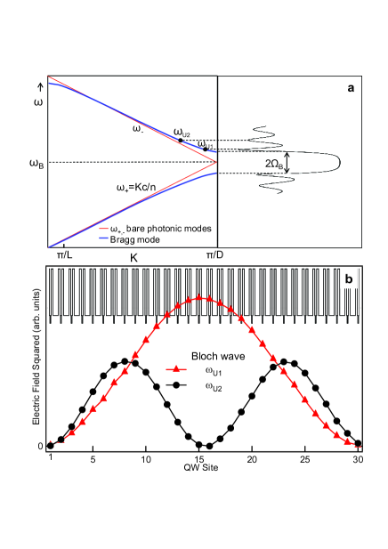
where, is the resonance frequency of two degenerate exciton modes and , is the Bragg frequency corresponding to the center of PBG, is the half–width of PBG and is the vacuum Rabi splitting measuring the strength of the exciton–photon interaction in the structure. It is worth noticing that the two exciton modes are degenerate because excitons in different QWs are well separated and do not interact directly with each other. As shown in Figure 3, the energies of the uncoupled photonic modes and can be expressed in terms of the Bloch wavevector as and , where is the period of the structure. The value of the Bragg frequency is given by , the parameter which is varied during the experiment by varying the period of the structure. The Hamiltonian (1) can be simplified if instead of the bare photonic and excitonic basis states, we use the basis of upper and lower photonic Bloch modes and – obtained by direct diagonalization of the photonic part – and symmetric and antisymmetric combination of excitonic Bloch states and . Expressed in the new basis, the Hamiltonian (1) has a simpler form
| (2) |
where and represent the frequencies of the upper and lower photonic Bloch modes.
While in an infinite Bragg reflector the Bloch wavevector has a continuous spectrum, in our finite size system, and are complex due to radiation losses and take discrete values. These define the eigenmodes of the finite Bragg reflector with frequencies and on the upper and lower sides of the PBG, corresponding to minima in the reflection spectrum outside the PBG beggs (see Figure 3). Here , denote respective radiative decay rates which decrease with increasing number of periods. Notably, modes with different , are well separated and orthogonal to each other and we thus consider interaction of the exciton with only the first Bragg mode. The exciton eigenfrequency is also complex: with being the inverse of the exciton lifetime. For the conditions of our experiments, when the exciton frequency is in the vicinity of the upper photonic Bloch mode , assuming , the interaction between the exciton states , and the lower photonic state can be neglected. Recalling the definition of detuning as the difference between the upper edge of the PBG and the exciton resonance frequency, , the Hamiltonian reads
| (3) |
and has three eigenfrequencies:
| (4) | |||||
corresponding to the triplet of branches observed in the experiments. Here, . Therefore, the three modes result from the coupling of one photonic mode to two excitonic ones. In Figure 2(c) the three branches predicted from the coupled oscillator model are plotted as a function of the detuning (grey solid lines), showing excellent agreement with the experimental data (black circles).
Remarkably, the real part of the middle branch eigenfrequency does not vary with detuning since the asymmetric photonic Bloch mode does not interact with the symmetric exciton Bloch mode panzarini . This can be directly envisioned when plotting in Figure 3(b) the squared electric field at the QW sites calculated for the first and second Bragg modes in the absence of the excitonic absorption. As expected, the electric field envelope corresponds to a Bloch wave exhibiting half a cycle within the structure. Furthermore, it is seen that only a fraction of the structure’s 30 QWs contribute towards strong coupling, namely the ones positioned in the high field region, whereas the rest in the low field region remain uncoupled. This picture can differ substantially in structures with narrow PBG where exciton coupling to both photonic Bloch modes on either side of the PBG can occur. Such coupling mixes all four modes and introduces dispersion to the middle branch goldberg . However, in the latter case the individual modes become less pronounced as opposed to the sharp modes of this study.
The investigated Bragg structure presents several important advantages over the conventional strongly coupled microcavity system: a) it ensures maximal overlap between the exciton wavefunction and the light mode as opposed to microcavity in which electric field penetration into the mirrors reduces Rabi splitting b) constitutes a universal approach which allows incorporation of wide variety of high refractive index contrast organic/inorganic materials using layer by layer deposition c) offers an alternative approach to achieving strong coupling regime in material systems such as GaN where strain buildup poses serious limitations baumberg .
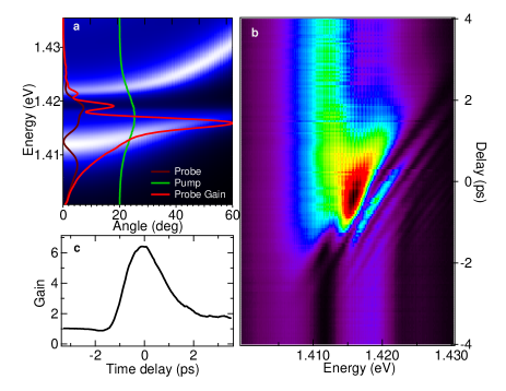
To confirm the potential of Bragg polaritons we explore their nonlinear properties in angle-resonant polariton parametric amplification geometry amplifier exploiting their microcavity-like dispersion relations [Fig. 4(a)]. We use spectrally filtered 3.5meV bandwidth 1ps pump pulses to resonantly excite lower polariton branch at the “magic” angle. Broadband 150fs probe pulses are incident normal to the sample and their time-dependent reflectivity changes are recorded. In [Fig. 4(a)] probe reflectivity spectra in the absence of the pump is presented, clearly showing polariton dips at all three branches (purple line). With the pump on the reflected probe spectrum at zero time delay changes dramatically: a strong peak appears, blue shifted by 3.5meV with respect to the bare lower polariton reflectivity dip, and yields a peak gain of 6.4 [Fig. 4(c)]. While this blue shift is larger than that generally observed in III-V microcavities amplifier , it remains smaller than half the Rabi splitting. The temporal dynamics of the normalized probe spectra [Fig.4(b)] show an ultrafast (1.8ps) response for the main gain peak [Fig.4(c)], similar to parametric amplification in conventional microcavities amplifier . The well resolved spectral fringes on the side of the main gain peak seen in Fig.4(b) are ascribed to typical feature arising from the energy-shifting resonance in time integrated spectra at fixed pump-probe time delay (see Berstermann ). Finally, compared to the case of strongly coupled planar microcavity, the gain peak is broader (2.5meV) due to broader polariton resonances and shorter polariton lifetimes.
In conclusion, we show that our unfolded microcavity structure offers a novel laboratory for the exploration of the strong coupling regime. Tuning of the characteristic mode of a Bragg structure through the excitonic resonance produces strong coupling with the appearance of mixed Bragg polariton states. Interpreting the eigenmodes of the structure in terms of the normal modes of a coupled harmonic oscillator system closely reproduces the Bragg polariton branches. Our results suggest that Bragg polaritons owing to their excitonic content can exhibit large nonlinearities. Furthermore their polariton–like dispersion offers new opportunities for the study of nonlinear phenomena such as stimulated scattering, amplification and Bragg polariton lasing.
This research was supported by the Greek GSRT, project PENED 2003, No: 03E816 and EU ITN projects “CLERMONT 4” and “ICARUS”. The authors are thankful to A. V. Kavokin for stimulating discussions.
References
- (1) C. Weisbuch et al. Phys. Rev. Lett. 69, 3314 (1992).
- (2) S. I. Tsintzos, N. T. Pelekanos, G. Konstantinidis, Z. Hatzopoulos, and P.G. Savvidis, Nature 435, 372 (2008). D. Bajoni et al. Phys. Rev. B 77, 113303 (2008). A. A. Khalifa et al. Appl. Phys. Lett. 92, 061107 (2008).
- (3) T. C. H. Liew et al. Phys. Rev. B 82, 033302 (2010).
- (4) G. Christmann et al. , Phys. Rev. B 82, 113308 (2010).
- (5) S. Christopoulos et al., Phys. Rev. Lett. 98, 126405 (2007).
- (6) A. Imamoglu, R. J. Ram, S. Pau, and Y. Yamamoto, Phys. Rev. A 53, 4250 (1996)
- (7) H. Deng, G. Weihs, D. Snoke, J. Bloch, and Y. Yamamoto, PNAS 100, 15318-15323 (2003).
- (8) V. Savona, J. Cryst. Growth 184, 737 (1998).
- (9) S. I. Tsintzos, P. G. Savvidis, G. Deligiorgis, Z. Hatzopoulos, and N. T. Pelekanos Appl. Phys. Lett. 94, 071109 (2009).
- (10) J. Bloch, T. Freixanet, J. Y. Marzin, V. Thierry-Mieg, and R. Planel, Appl. Phys. Lett. 73, 1694 (1998).
- (11) S. Faure et al. Appl. Phys. Lett. 95, 121102 (2009).
- (12) F. Biancalana, L. Mouchliadis, C. Creatore, S. Osborne, and W. Langbein, Phys. Rev. B 80,121306R (2009).
- (13) D. Goldberg et al. , Nature Photonics 3, 662 (2009).
- (14) M. Richard, R. Romestain, R. André, and Le Si Dang, Appl. Phys. Lett. 86, 071916 (2005).
- (15) A. Y. Sivachenko, M. E. Raikh, and Z. V. Vardeny, Phys. Rev. A 64, 013809 (2001).
- (16) A. Armitage et al. Phys.Rev. B. 57, 14877 (1998).
- (17) E. L. Ivchenko, M. A. Kaliteevski, A. V. Kavokin, and A. I. Nesvizhskii, J. Opt. Soc. Am . B 13, 1061 (1996).
- (18) M. A. Kaliteevski, D. M. Beggs, S. Brand, R. A. Abram, and V. V. Nikolaev, Phys.Rev. B. 73, 033106 (2006).
- (19) M. Bellanger, V. Bousquet, G. Christmann, J. Baumberg, and M. Kauer Appl. Phys. Express 2, 121003(2009).
- (20) P.G. Savvidis et al., Phys. Rev. Lett. 84, 1547 (2000).
- (21) T. Berstermann et al. Phys. Rev. B 80, 075301 (2009).