Theory of I-V Characteristics of Magnetic Josephson Junctions
Abstract
We analyze the electrical characteristics of a circuit consisting of a free thin-film magnetic layer and source and drain electrodes that have opposite magnetization orientations along the free magnet’s two hard directions. We find that when the circuit’s current exceeds a critical value there is a sudden resistance increase which can be large in relative terms if the currents to source or drain are strongly spin polarized and the free magnet is thin. This behavior can be partly understood in terms of a close analogy between the magnetic circuit and a Josephson junction.
pacs:
85.75.-d 75.47.-m 75.75.-c 72.25.-bI Introduction
Electronic transport can usually be described in terms of effectively independent electrons. Recently, with the discovery and exploitation of spin-transfer torqueslonczewski_stt ; berger_stt ; tsoi_stt ; ralph_stt (STT) effects, magnetism has joined superconductivity as an instance in which collective and quasiparticle contributions to transport are entwined in an essential way. The similarity between the non-equilibrium properties of magnetic and superconductingnonequilsuper systems is especially close when comparing the properties of a superconducting circuit containing a Josephson junction to a magnetic circuit containing a free ferromagnetic layer with strong easy-plane anisotropy. As we explain in more detail below, the role of the Josephson junction bias current in the superconducting circuit is played in the magnetic case by the component of the spin-current injected into the nanoparticle that is perpendicular to the easy plane.
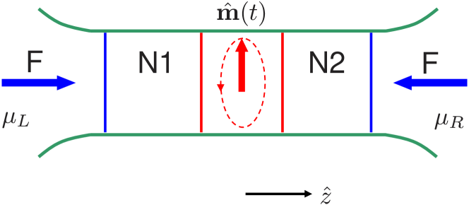
The electrical properties of a circuit containing a Josephson junction typically change drastically when the junction’s critical current is exceeded. In this paper we propose that the magnetic circuit illustrated in Fig. 1, which we refer to as a magnetic Josephson junction (MJJ), can exhibit similar drastic effects when a critical current related to the free magnet’s in-plane anisotropy is exceeded. We show that the resistance of an MJJ can increase substantially when its critical current is exceeded provided that either source or drain currents are strongly spin polarized and magnetization relaxation in the free magnet layer is not too rapid.
The analogy we explore is closely related to the early suggestion by Bergerberger_JJ that 180∘ domain walls in ferromagnets should exhibit behavior analogous to the behavior of Josephson junctions. Indeed the MJJ geometry we propose may be viewed as a discrete version of a pinned 180∘ domain wall. Although the magnetization dynamics induced emf that Berger predicted based on an analogy to the ac Josephson relation has nowbeach_1 ; beach_2 been confirmed experimentally, electrical signals of magnetization texture dynamics in uniform bulk materials tend to be weak. The MJJ geometry we study is also closely related to that employed in spin-transfer torque oscillators. silva_sto It is well known that the dc resistance of an STT-oscillator tends to increase once the magnetization becomes dynamic. tsoi_stt The increase in bias voltage at fixed current is closely related to Berger’s Josephson voltage. From this point of view, the issue we explore theoretically in this paper is the possibility of achieving large relative changes of resistance in an STT-oscillator when the magnetization becomes dynamic. We believe that such an examination is motivated by recent advances in ferromagnetic metal spintronics perpendicular ; strongly which have enabled the injection of more highly spin polarized currents and decreased the thickness of free magnetic layers, making them easier to manipulate electrically. MJJ devices not only provide a test bed for our understanding of the fundamental physics of spin gauge fields, but could also be useful because of their unusual transport properties.
Our paper is organized as following. In Sec. II, we comment at greater length on the relationship between Josephson junctions and easy-plane free magnets. In Sec. III, we discuss the theoretical framework we used for analyzing the transport properties of an MJJ. In Sec. IV and Sec. V, we identify two regimes in which the MJJ could have quite different resistances. Finally, in Sec. VI, we summarize our results and discuss our conclusions.
II Nanomagnet Equations of Motion
As shown in Fig. 1, the MJJ is a multilayer heterostructure consisting of ferromagnetic and non-magnetic normal metal layers. The two ferromagnetic electrodes have opposite magnetization directions, serving as spin polarized current source and drain. The free magnetic layer in the middle is sandwiched between two non-magnetic normal metal spacer layers to avoid direct magnetic coupling with the electrodes. We assume that the free magnetic layer is small enough that its magnetization is spatially constant. Its magnetization direction dynamics is then described by a Landau-Liftshitz-Gilbert (LLG) equation,
| (1) |
where is a unit vector along the magnetization direction of the free layer, is (minus) the gyromagnetic ratio, is an effective magnetic field, is the dimensionless Gilbert damping constant and the right hand size of the equation above denotes a Slonczewskislonczewski_stt ; berger_stt ; tsoi_stt ; ralph_stt spin-transfer torque termspintransfercaveat that captures the coupling between transport and collective dynamics:
| (2) |
Here is the magnitude of the total spin of the free magnetic layer, is the free layer volume, is its magnetization per unit volume, is the net spin current flowing out of the free layer and selects the component of that is transverse to . We assume that there is no applied magnetic field. The effective magnetic field,
| (3) |
then arises mainly from the magnetostatic energy of a thin film with an elliptical cross-section:
| (4) |
where is the magnetization orientation azimuthal angle and the anisotropy parameter so that the magnetization direction is always close to its easy plane. When the magnetization direction is expressed in terms of and , and is assumed to be small, the LLG equations take the form
| (5) |
| (6) |
As discussed later we will be most interested in circumstances under which and , the component of spin-current in the azimuthal direction, vanishes. In that limit the right hand side of the equation for reduces to the difference between the chemical potential of majority and minority spin electrons. Eq. (5) is then precisely equivalent to the resistively and capacitively shunted Josephson junction modeltinkham with easy-plane anisotropy playing the role of the capacitance,
| (7) |
in-plane anisotropy playing the role of the superconducting coupling which supports a supercurrent
| (8) |
playing the role of a dissipative quasiparticle current, and the spin-transfer torque term playing the role of junction bias current.
It is well known that the electrical properties of a Josephson junction changes drastically at its critical current. Due to the connections revealed above, we expect that similar behavior can occur in an MJJ. Because the MJJ bias current is a spin-current not a charge current, and its dissipationless supercurrent transports spins from up to down states not charges from one side of the junction to the other, the current-voltage relationship of a circuit in which an MJJ is embedded is more subtle than in the superconducting Josephson junction case, and collective effects are generally weaker. In the following, we analyze MJJ I-V relationships with the aim of identifying circumstances under which the resistance change at the critical current can be large in circuits that are fabricated with modern spintronic materials.
III Magnetoelectronic Circuit Theory
For small bias voltages the nanoparticle magnetization can achieve a static value by balancing the circuit bias and collective transport terms: . Once reaches its maximum value, , the magnetization’s azimuthal angle becomes time-dependent and the time average of quickly becomes negligible. In this dynamic limit must be balanced against the dissipative term . Our main goal in this section is to shed light on the requirements for a substantial relative change in circuit resistance when the MJJ’s critical current is exceeded. For this purpose we use magnetoelectronic circuit theory,Tserkovnyak_RMP ; Brataas_PRL ; Brataas_Review which simplifies the transport problem in ferromagnet/normal metal heterostructures by dropping some non-local effects and separating the circuit into normal metal and magnetic constituents within which the exchange field is taken to be constant in direction. In the following, we assume that the ferromagnetic layer is thicker than the magnetic coherence length Brataas_Review which is on the order of in transition metals.
Magnetoelectronic circuit theory’s key equation relates the charge and spin currents that flow from a ferromagnet into a normal metal to the ferromagnet’s chemical potential and to the chemical potential of the normal metal, including its non-equilibrium spin-accumulation contributions. The charge current
| (9) |
Here and refer to majority and minority spins, is the ferromagnet’s magnetization direction, is a dimensionless spin-dependent conductance, is the normal metal chemical potential averaged over spin states while represents the magnitude and direction in spin-space of the spin-dependent part of the normal metal’s chemical potential. For static magnetization the analogous spin-current expressiongcaveat is
| (10) |
Eqs. (9, 10) apply to the four ferromagnet/normal metal interfaces in a MJJ. We assume that the normal metal nodes have sizes smaller than the spin flip diffusion length, allowing its spin flip scattering to be neglected. Setting the total charge and spin-currents into each of the two normal metal nodes to zero yields eight equations for the eight unknown parameters which specify the spin-dependent chemical potentials of the two normal metal nodes. In the following two sections, we shall calculate the resistance for both the static regime and the dynamic regime from this set of equations.
IV Static MJJ Resistance
To apply magnetoelectric circuit theory to an MJJ with a time-independent free magnet, we note that for source and drain electrodes respectively, set the source and drain chemical potentials to and assume that source and drain ferromagnetic electrodes are identical. It follows from symmetry that spin-accumulation in the direction perpendicular to and vanishes in both normal metal nodes, reducing the number of free variables to six. We separate the normal metal chemical potentials into accumulation () and transport () contributions defined by
| (11) |
where for charge, free magnet, and source spin directions, and denotes the -th normal metal node.
Simple equations for can be obtained by adding and subtracting the charge and spin conservation conditions for the two nodes. In this way it is easy to verify that for the static case , properties that also can be established by symmetry considerations. The three remaining equations determine the chemical potential differences that drive charge and spin across the free magnetic layer, and , and the accumulation of spin injected by the source and drain electrodes :
| (12) |
where we have introduced the shorthand notations , and for the interfaces between normal metal and source and drain electrodes. The corresponding upper case ’s and refer to interfaces between the normal metals and the free magnetic layer.
The charge current is most conveniently evaluated at either source or drain electrode with the result that . Although the static MJJ resistance depends on the detailed values of the various interface conductance parameters, it tends to be close to the sum of the individual interface resistances and is not especially sensitive to source or drain electrode spin-polarization; in the limit in which all ferromagnets are fully polarized and identical, for example, the static MJJ resistance is . This result applies until the perpendicular spin current reaches its critical value . The corresponding critical charge current flowing through the MJJ is proportional to . For typical values , , J (per m3) and assuming that , the citical charge current density is on the order of A/nm2 for a free layer with a thickness around nm.
V Dynamic MJJ Resistance
When is substantially larger than a dynamic steady state is approached in which
| (13) |
This precession of magnetization induced by spin current is the working principle of STT-oscillators. Because of their long spin relaxation times, the normal metal nodes do not follow this precession so that the components of the spin-dependent part of the chemical potentials vanish along directions other than . This leaves four unknown chemical potentials and to be determined by Eq. (13) and the four circuit equations for conservation of and at each node. In the dynamic case the total spin-current flowing out of the free magnet includes a spin-pumping contribution: Tserkovnyak_RMP ; Tserkovnyak_spinpumping
| (14) |
The induced pumping current tends to counter the bias current, effectively increasing the resistance. Following the same strategy as in the static case we find that while the remaining unknowns satisfy
| (15) |
The third of these equations relates the spin-current out of the free nanoparticle to the spin decay rate. The electrical properties of a MJJ are most interesting when the dimensionless coupling constant formed by comparing the right and left hand sides of Eq. (V),
| (16) |
is small. Taking typical valuesTserkovnyak_RMP of (per nm2), and of yields , where is the film thickness, suggesting that small values are possible in thin magnetic films made from materials like permalloy that have small values of . Solving Eqs. (V) for we find that the dynamic MJJ resistance
| (17) |
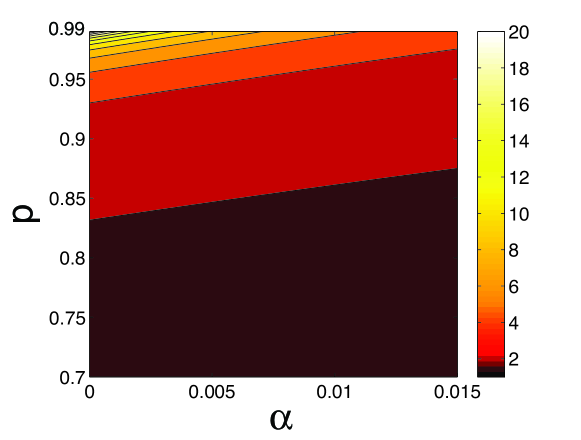
which diverges for . When source and drain electrodes are strongly spin-polarized and is small, the MJJ circuit should suffer a large increase in resistance at its critical current.
This drastic resistance change can be qualitatively explained as follows. In the static regime, the free layer magnetized in the -plane breaks spin rotation symmetry along -axis. Exchange-field driven spin flips then provides a path for electrical conduction between oppositely polarized electrodes. In the dynamic regime, precession of the free layer restores spin rotation symmetry and the -component of the conduction electron spin is approximately conserved, increasing the electrical flow resistance.
In Fig. 2, we plot the ratio , which characterizes the performance of a MJJ, as a function of the damping parameter and the polarization . increases as decreases or increases, and diverges in the limit and .
VI Discussion
The influence of magnetization dynamics on electronic transport can be described by accounting for spin pumping, as in the analysis summarized above, or equivalently by accounting for a dynamics induced emf. For a slowly varying magnetic texture like a domain wall in transition metal ferromagnets, a transport electron follows the local magnetization direction adiabatically. The induced emf isbeach_1 ; beach_2 then given by with being the domain wall precession frequency and the bulk transport current spin-polarization. For the MJJ considered here, spin transport is no longer adiabatic. In order to relate the two perspectives we assume that the influence of precession in the MJJ can also be captured by imposing an extra emf that accounts for the difference between static and dynamic circuit resistances:
| (18) |
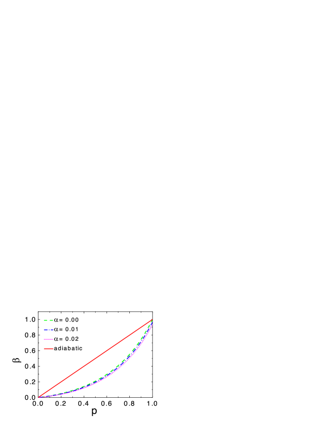
The effective value of then depends on microscopic MJJ parameters and can be evaluated by comparing Eq. (18) with the results of a magnetoelectronic circuit analysis. Some typical values of are plotted in Fig. 3 as a function of () for different values of . For the completely adiabatic case, we should expect which is a straight line in the figure. Although the of a MJJ generally deviates from this straight line due to nonadiabatic effects, it approaches the straight line in the and limits. For , the same result can be obtained by making a unitary transformation into the rotating frame of and the result amounts to a relative shift between the chemical potentials of the two electrodes. We find that the magnetization dynamics damping, parameterized by , slightly decreases the value of because the dissipation of energy through damping can be regarded as an extra resistance in the circuit.
From the analysis above, the current drops once bias voltage increases above a critical value determined by the in-plane anisotropy, i.e. when the precession of magnetization begins. This signals a negative resistance region of the I-V curve similar to that for the Gunn diode. hess For MJJ with high performance (), it could be used as a good fuse link, for example, to control the maximum current that can flow through a circuit.
To summarize, we propose a ferromagnet/normal metal heterostructure which has properties analogous to those of a Josephson junction. We analyze its I-V characteristics and identify a static regime in which the magnetization configuration is static with a low resistance and a dynamic regime in which the magnetization precesses and the resistance is high. Our analysis indicates that MJJ circuits which exhibit large and sudden relative change in resistance can be fabricated using modern spintronic materials with perpendicular anisotropyperpendicular and strongly polarized spin currentsstrongly . Besides having an academic interest, because of the insight that it provides in comparing current-induced emf and spin-pumping notions in metal spintronics, the MJJ may be useful for applications.
VII Acknowledgements
The authors thank Tomas Jungwirth, Jairo Sinova and Maxim Tsoi for helpful discussions. This work was supported by NSF (DMR0906025), the Welch Foundation grant F1473, DOE (DE-FG02-02ER45958, Division of Materials Science and Engineering) and Texas Advanced Research Program.
References
- (1) J. C. Slonczewski, J. Magn. Magn. Mater. 159, L1 (1996).
- (2) L. Berger, Phys. Rev. B 54, 9353 (1996).
- (3) M. Tsoi, A.G.M. Jansen, J. Bass, W.C. Chiang, J. Seck, V. Tsoi, and P. Wyder, Phys. Rev. Lett. 80, 4281 (1998).
- (4) D. C. Ralph, and M. D. Stiles, J. Magn. Magn. Mater. 320, 1190 (2008).
- (5) See for example N. B. Kopnin, Theory of Nonequilibrium Superconductivity, (Oxford, 2001).
- (6) L. Berger, J. Appl. Phys. 55, 1954 (1984).
- (7) S. A. Yang, G.S.D. Beach, C. Knutson, D. Xiao, Q. Niu, M. Tsoi, and J. L. Erskine, Phys. Rev. Lett. 102, 067201 (2009).
- (8) S. A. Yang, G.S.D. Beach, C. Knutson, D. Xiao, Z. Zhang, M. Tsoi, Q. Niu, A. H. MacDonald, and J. L. Erskine, Phys. Rev. B 82, 054410 (2010).
- (9) T. J. Silva and W. H. Rippard, J. Magn. Magn. Mater. 320, 1260 (2008).
- (10) N. Nishimura, T. Hirai, A. Koganei, T. Ikeda, K. Okano, Y. Sekiguchi, and Y. Osada, J. Appl. Phys. 91, 5246 (2002).
- (11) S.S.P. Parkin, C. Kaiser, A. Panchula, P.M. Rice, B. Hughes, M. Samant, and S. H. Yang, Nature Mater. 3, 862 (2004); S. Yuasa, T. Nagahama, A. Fukushima, Y. Suzuki, and K. Ando, Nature Mater. 3, 868 (2004).
- (12) Besides Slonczewski spin-transfer term, which captures the overall conservation of angular momentum, there can be other contributions to the coupling between transport currents and magnetization dynamics. See Ref.[ralph_stt, ].
- (13) See for example M. Tinkham, Introduction to Superconductivity, (McGraw-Hill, 1996).
- (14) Y. Tserkovnyak, A. Brataas, G. E. W. Bauer, and B. I. Halperin, Rev. Mod. Phys. 77, 1375 (2005).
- (15) A. Brataas, Y.V. Nazarov, and G.E.W. Bauer, Phys. Rev. Lett. 84, 2481 (2000).
- (16) A. Brataas, G.E.W. Bauer, and P.J. Kelly, Phys. Rep. 427, 157 (2006).
- (17) Y. Tserkovnyak, A. Brataas, and G. E. W. Bauer, Phys. Rev. Lett. 88, 117601 (2002).
- (18) We have in the interests of transparency dropped a small term proportional to the imaginary part of the spin-flip conductance that does not play an essential role in our discussion.
- (19) See for example K. Hess, Advanced Theory of Semiconductor Devices, (IEEE Press, 2000).