Atomistic pseudopotential calculations of the optical properties of InAs/InP self-assembled quantum dots
Abstract
We present a comprehensive study of the optical properties of InAs/InP self-assembled quantum dots (QDs) using an empirical pseudopotential method and configuration interaction treatment of the many-particle effects. The results are compared to those of InAs/GaAs QDs. The main results are: (i) The alignment of emission lines of neutral exciton, charged exciton and biexciton in InAs/InP QDs is quite different from that in InAs/GaAs QDs. (ii) The hidden correlation in InAs/InP QDs is 0.7 - 0.9 meV, smaller than that in InAs/GaAs QDs. (iii) The radiative lifetimes of neutral exciton, charged exciton and biexciton in InAs/InP QDs are about twice longer than those in InAs/GaAs QDs. (v) The phase diagrams of few electrons and holes in InAs/InP QDs differ greatly from those in InAs/GaAs QDs. The filling orders of electrons and holes are shown to obey the Hund’s rule and Aufbau principle, and therefore the photoluminescence spectra of highly charged excitons are very different from those of InAs/GaAs QDs.
pacs:
73.21.La, 71.35.Pq, 78.67.HcI Introduction
Self-assembled quantum dots (QDs) have attracted great interest in the past two decades due to their potential applications in the optoelectronic devices Huffaker et al. (1998); Djie et al. (2007); Shields (2007) and quantum information science,Bonadeo et al. (2000); Xu et al. (2007a, b); Atatüre et al. (2006), such as high-efficiency and low-threshold lasers, Huffaker et al. (1998) single photon source,Michler et al. (2000); Imamoglu and Yamamoto (1994); Yuan et al. (2002) entangled photon emitters,Stevenson et al. (2006); Akopian et al. (2006) and qubits etc.Loss and DiVincenzo (1998); Xu et al. (2007a, b) These applications all take the advantages of the unique properties of the QDs which have discrete energy levels and sharp absorption/emission linesFinley et al. (2001); Ware et al. (2005); Gammon et al. (1996) due to the three-dimensional confinement effects.
Until very recently, most of the experimental and theoretical works focus on InAs/GaAs QDs Bayer et al. (2002); Bayer and Forche (2003); Bonadeo et al. (2000); Huffaker et al. (1998); Reuter et al. (2005); Fonseca et al. (1998); Bock et al. (2002); Stier et al. (1999); Williamson and Zunger (1999); Wang et al. (1999); Williamson et al. (2000, 2001); He et al. (2004). Huge progress has been made both in understanding of the fundamental physics and towards real applications of these QDs. For examples, the entangled photon sources from biexciton cascade process have been demonstrated experimentally.Stevenson et al. (2006); Akopian et al. (2006) The strong coupling between QDs and cavity has been achieved. Reithmaier et al. (2004); Yoshie et al. (2004); Hennessy et al. (2007) The coherently manipulation of single charge and spin in InAs/GaAs QDs have also been demonstrated. Kamada et al. (2001); Zrenner et al. (2002); Stievater et al. (2001); Xu et al. (2007b); Emary et al. (2007); Ramsay et al. (2008) These achievements make QDs extraordinary promising candidates for quantum information applications. Theoretically, the electronic structures and optical properties of InAs/GaAs QDs have been studied intensively via both methods, Bahder (1990); Nakaoka et al. (2004); Pryor (1998, 1999); Pryor et al. (1997) and the microscopic models.Wang and Zunger (1999); Williamson et al. (2000); Bryant and Jaskolski (2003)
On the other hand, InAs/InP QDs have attracted interest only very recently Gong et al. (2004); Caroff et al. (2005); Kim et al. (2009); Reimer et al. (2009); Cornet et al. (2006) mainly because their emission wavelengths are naturally around 1.55 m (-band), which are ideal for fiber optical telecommunication applications. Compared to InAs/GaAs QDs, there are much fewer works on InAs/InP QDs, both experimentally and theoretically. It has been shown from atomistic pseudopotential calculations that the electronic structures of InAs/InP QDs differs greatly from those of InAs/GaAs QDs,Gong et al. (2008) even though they have the same dot material, but different matrix material. Interestingly, it has been found He et al. (2008) that the fine structure splittings (FSS) in InAs/InP(001) QDs are very small, which is very suitable for -band entangled photon source. Indeed, recent experiments indicate that InAs/InP QDs do not have significant FSS.Sasakura et al. (2009)
However, the optical properties of InAs/InP QDs has not yet been systematically studied. In this work, we present a comprehensive study of the optical properties of InAs/InP QDs using an atomistic empirical pseudopotential method and the configuration interaction (CI) treatment of the many-particle effects.Wang and Zunger (1999) The methods have been successfully applied to InAs/GaAs QDs, and obtained many results that are very good agreement with experiments. Ediger et al. (2005, 2007a) A nice review of the methods can be found in Ref. [Bester, 2009]. We find that the photoluminescence (PL) spectra of InAs/InP QDs are very different from those of InAs/GaAs QDs in many aspects, including the alignment of emission lines of the neutral exciton, charged excitons and biexciton, the hidden correlation, the radiative lifetimes, and the highly charged PL spectra. We hope this work can provide helpful insight for the optical properties of InAs/InP QDs.
The rest of the work is organized as follows. In Sec. II, we outline the methods used in our calculations. In Sec. III.1 and Sec. III.2 we discuss the binding energies and the hidden correlation in InAs/InP QDs. The radiative lifetimes of exciton, biexciton, and trions are discussed in Sec. III.3. The phase diagrams of electrons and holes in InAs/InP QDs are presented in Sec. III.4, whereas the highly charged exciton PL spectra in InAs/InP QDs are discussed in Sec. III.5. We summarize in Sec. IV.
II Methods
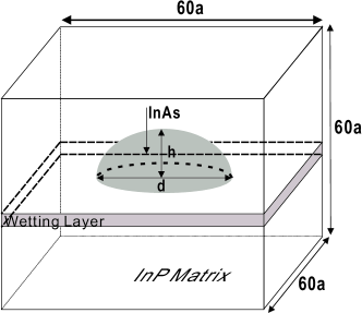
Figure 1 depict the geometry of the QD system used in our calculations. The lens-shaped InAs QD is embedded in the center of the 60 6060 InP 8-atom unit cell on the top of a two-monolayer wetting layer. The single-particle electronic structures of the QDs are calculated via an empirical pseudopotential method,Wang and Zunger (1999); Williamson et al. (2000) whereas the many-particle effects are treated via a configuration interaction method, as follows.
We first obtain the atomic positions of the QDs structure. This is done by minimizing the strain energy of the system via the valance force field (VFF) method,Keating (1966); Martin (1970) which has been demonstrated to be a good approximation for semiconductors. Once we obtain the relaxed positions of all the atoms of type at site , we calculate the total electron-ion potential as a superposition of the local screened atomic pseudopotentials , the total (nonlocal) spin-orbit (SO) potential . Williamson et al. (2000) The Schrödinger equation,
| (1) |
is solved by using a linear combination of bulk bands (LCBB) method, Wang and Zunger (1999) in a basis of Bloch orbitals of band index and wave vector of material (= InAs, InP), strained uniformly to strain . For each material , we used a basis set of = 6 bands (including spin) for the hole states and = 2 for the electron states, on a k-point mesh around the point. It has been shown that the energy levels changes in InAs/GaAs QDs due to the piezoelectric effects are quite small. Bester and Zunger (2005) Because the lattice mismatch in the InAs/InP QDs is only half of that of the InAs/GaAs QDs, we expect that the piezo-effect should be even smaller in the InAs/InP dots, and therefore the piezoelectric potential is neglected in the calculations.
Due to the spatial confinement, the carriers in the QDs have strong Coulomb interactions. The many-particle Hamiltonian reads,
| (2) |
where is the single particle levels obtained in Eq. (1). is the Coulomb integral matrix, i.e.,
| (3) |
where is the full screened dielectric constant. Franceschetti et al. (1999) The many-particle Hamiltonians are solved by using a configuration interaction (CI) method in which the Hamiltonians are diagonalized in the Slater determinant basis.Franceschetti and Zunger (2000) This method has been successfully applied to study the optical properties of InAs/GaAs QDs, and the obtained results are in excellent agreement with experiments.Ediger et al. (2005, 2007a, 2007b); Ding et al. (2010); Williamson et al. (2000)
III Results
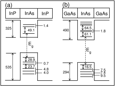
Figure 2 (a) and (b) show the single-particle energy levels for typical InAs/InP and InAs/GaAs QDs, respectively, with height =2.5 nm and diameter =25 nm. The differences between the single-particle electronic structures of the two dots have been addressed in Ref. [Gong et al., 2008]. Here we merely outline the main differences between the two dots that are related to this work. (i) The confinement of electron and hole in InAs/GaAs QDs is 490 and 294 meV, while in InAs/InP QDs is 325 and 535 meV, respectively. Therefore, holes (electrons) are much more (less) confined in InAs/InP QDs. (ii) Due to the much smaller confinement potential for electrons in the InAs/InP QDs, fewer electron states are confined. (iii) The -orbit energy splitting of electrons and holes in InAs/GaAs QDs are about 1.8 meV and 7.5 meV respectively, whereas in InAs/InP QDs, they are 1.4 meV and 0.7 meV, respectively. (iv) The hole states in tall InAs/GaAs QDs can be localized in the interface, but in InAs/InP QDs, hole levels have well defined shell structure and no localization has been observed. These differences can greatly influence the optical properties of InAs/InP QDs, as will be shown in the following sections.
III.1 Binding energies of , and
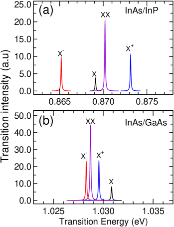
A typical PL spectra for lens-shaped InAs/InP and InAs/GaAs QDs with nm and nm are presented in Fig. 3 (a) and (b), respectively. We focus on the alignment of emission line of ( , , and ). The calculated alignment of in InAs/GaAs QDs agrees well with experimental results in Refs. [Xu et al., 2007b; Warming et al., 2009; Siebert et al., 2009; Dalgarno et al., 2008; Rodt et al., 2005], and previous calculations by Narvaez et al.Narvaez et al. (2005a, b).
The binding energy of is defined as,
| (4) |
where is the corresponding recombination energy. In the Hartree-Fock approximation, can be calculated as,Bester and Zunger (2003); Narvaez et al. (2005b, a) , , , , where (see Fig. 2), () is the direct Coulomb interaction between two electrons (holes), and is the direct Coulomb interaction between electron and hole of levels. Here, we neglect the exchange interactions, which is much smaller than the direct Coulomb interactions. With these analytical expressions, we have
| (5) | |||
The values of , and for InAs/InP QDs and InAs/GaAs QDs are shown in Fig. 4. For InAs/InP QDs, we see . This is because in InAs/InP QDs, holes are much more localized than electrons. In contrast, in InAs/GaAs QDs, we find the same order for , , , for 3 nm, but reversed order when 3.0 nm. Equation (5) can be used to explain the alignment of of InAs/InP QDs as shown in Fig. 3 (a), but can not explain the alignment of in InAs/GaAs QDs. This is because in InAs/InP, 6.2 meV, and 3.2 meV, much larger than the correlation energies, which is about 1 meV. However, in InAs/GaAs QDs, , and are very close. So the correlation energies play very important roles to determine the final alignment of . Bester and Zunger (2003) We therefore expect that the alignments (and binding energies) of in InAs/InP QDs are very different from those of InAs/GaAs QDs.
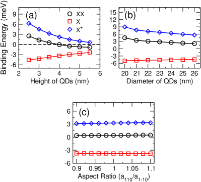
We show the binding energies of , and as functions of dot height, dot diameters and aspect ratio () in Fig. 5 (a), (b) (c) respectively. We find that the binding energies of and decrease dramatically with the increasing of dot height, whereas the binding energy of increases. For a lens-shaped dot with diameter =20 nm, the binding energy of equal zero, i.e., at dot height 4nm. At this special point, the dot can be used as an entangled photon emitter via the time-reordering scheme proposed by Avron et al.Avron et al. (2008) In contrast, the binding energy of is always positive, whereas the binding energy of is always negative, even though they all become small for very tall dots. As shown in Fig. 5 (c), there is no obvious shift of binding energies in elongated QDs when changes from 0.9 to 1.1. The observed trends of the binding energies for InAs/InP QDs differ greatly from those of InAs/GaAs QDs. For example, in InAs/GaAs QDs, the binding energies of and can be either positive or negative Bester and Zunger (2003) due to the cross over of the Coulomb interactions shown in Fig. 4 . These differences can be traced back to the difference of confinement potentials between the two dots.
III.2 Hidden correlation
The exciton binding energies change dramatically with the geometry and compositions of QDs. Recently proposed by some authors of the paper that the hidden correlation of QDs are always positive and remarkably constant for a large range of self-assembled QDs as a consequence of the Coulomb correlation effects. Zhang et al. The hidden correlation is defined as,
| (6) |
where has been defined in Eq. (4) and can be extracted directly from Fig. 5. Under the non-self-consistent Hartree-Fock approximation, the binding energies of , and cancel each other exactly (see also Eq. (5)), i.e., . Therefore the value that arise purely from the correlation effect. In Ref. [Zhang et al., ], it is shown that varies between 1.2 - 2.2 meV, for a wide range of geometry and exciton energies of InAs/GaAs QDs, which agrees well with all available experimental data from different groups.Zhang et al. The hidden correlation is also confirmed by the effective mass quantum Monte Carlo simulations.Zhang et al.
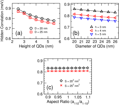
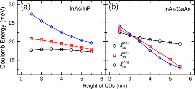
The hidden correlations in InAs/InP QDs is shown in Fig. 6, as functions of dot heights, diameters and aspect rations. We find meV for all QDs with different sizes and geometries studied here. The hidden correlation of InAs/InP QDs is smaller than that of InAs/GaAs QDs, which can be understood as follows. In InAs/InP QDs, the hole is more confined, so the energy level spacings are much larger than those in InAs/GaAs QDs (see Fig. 2) and therefore the correlation energies are reduced (see Ref. [Zhang et al., ]). Experimental confirmation is called for this prediction.
III.3 Lifetime of exciton, biexciton and trions
The radiative recombination lifetimes of exciton, biexciton and trion are very important parameters for many applications of the QDs. At low temperature, the lifetime is mainly determined by the dipole matrix element,
| (7) |
where is the dipole momentum and is the polarization vector of the electromagnetic field. The recombination lifetime at zero temperature can be calculated from,
| (8) |
where is the reflective index, and is the recombination energy. is the mass of the electron and is the velocity of light in vacuum. The linear dependence of on refractive index is applicable only when the QD and the matrix has similar dielectric constants. Narvaez et al. (2005b); Thränhardt et al. (2002) At finite temperature, the lifetime can be calculated as,Narvaez et al. (2005b)
| (9) |
where is occupation number of the initio state according to the Boltzmann distribution, and . Assuming that the thermalization between the dark and bright states is much longer than the exciton life time, we only take the bright states into consideration, which is somehow different from the treatment in Ref. [Narvaez et al., 2005b].
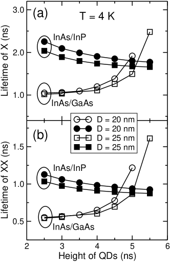
The radiative lifetimes of exciton in lens-shaped InAs/InP and InAs/GaAs QDs are compared in Fig. 7 (a). The major differences between the two dots are: (i) The exciton lifetime in InAs/InP is almost twice longer than that of InAs/GaAs for flat QDs. There are two reasons for the longer lifetime in InAs/InP QDs. First, InAs/InP QDs have smaller exciton energies and second, InAs/InP QDs have much smaller dipole moment, because the electrons are less confined. Experimentally, the lifetimes of and in InAs/GaAs QDs are found to be around 0.8 - 1.2 ns, Xu et al. (2007a, b); Gammon et al. (1996); Bayer and Forche (2003); Dalgarno et al. (2008) very close to the calculated results presented in Fig. 7. The measured exciton lifetimes in InAs/InP QDs by Sasakura et al,Sasakura et al. (2009) are about 2.0 ns, which also agree very well with the calculated values in this work. (ii) The exciton lifetime in InAs/InP QDs decreases with increasing of the dot height. In the InAs/GaAs QDs, the opposite trend is found, because the hole wave functions localize more on the interface of the dots. Gong et al. (2008) (iii) For flat QDs ( nm), we find that the exciton lifetime in InAs/GaAs dots is almost independent of the dot diameter. However, in InAs/InP QDs, the exciton lifetime depends strongly on the dot diameter. For example, when nm, = 2.5 nm, = 2.26 ns. When we increase to 25 nm, decrease to 2.04 ns. This is also due to the weak confinement potential for electrons in the InAs/InP QDs. Increasing the diameter of a QD results in more confined electron state, and thus lager overlap between electron and hole wave functions and lager dipole moment.
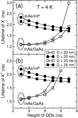
We further compare the lifetimes of biexciton in Fig. 7 (b), and of charged exciton between the two dots in Fig. 8. The values of lifetime for these exciton complexes are very different. However the trends of lifetimes as functions of dot geometry are rather similar. Roughly speaking, the charged excitons (, ) and have lifetimes about twice longer than the biexciton, Narvaez et al. (2005b) i.e.,
| (10) |
III.4 Phase diagrams of electrons and holes
The studies of electron/hole filling process in self-assembled QDs are stimulated by the experiments that allow the electron/hole be loaded into the QDs one by one and measure the charging energies.Drexler et al. (1994); Reuter et al. (2005) Unlike the atoms, where large Coulomb interaction eV ensure the Hund’s rule (maximum spin) and Aufbau principle. In self-assembled QDs, the Coulomb interaction is about 20 - 25 meV for electron-electron interaction and 15 - 20 meV for hole-hole interaction, which is the same order of the energy level spacings in QDs. So, the electron/hole filling process should be quite different from that in atoms. In strongly confined QDs (dimeter 3 nm), it is found that Hund’s rule is generally obeyed, but violation of the Aufbau principle is a common feature when single-particle energy levels separated by a few meV.Franceschetti and Zunger (2000) In the self-assembled InAs/GaAs QDs, He et alHe and Zunger (2006); He et al. (2005a) found that it is possible for holes to violate both the Hund’s Rule and the Aufbau Principe, which is confirmed by the PL spectra of highly charged excitons and by Ediger et al.Ediger et al. (2007a).
Let us first look at the charging energy and addition energy of the QDs, which can be measured directly in the experiments. The charging energy , measures the energy needed to load an additional carrier into the QDs. The addition energy is the energy difference between and , i.e., . In the Hartree-Fock approximation, the total energy of electrons confined in QDs can be calculated as,Franceschetti et al. (1999)
| (11) |
where is the occupation number of the -th level. The diagonal Coulomb energy and the exchange energy (see Eq. 3).
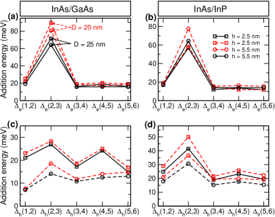
The electron/hole addition energies are presented in Fig. 9 (a),(c), for InAs/GaAs dots and in Fig. 9 (b) , (d) for InAs/InP QDs, respectively. The electron addition energies of InAs/InP QDs are much smaller than those of InAs/GaAs QDs of similar sizes. However, the hole addition energies of InAs/InP QDs are much larger than those of InAs/GaAs QDs due to their much larger single-particle level spacings, as illustrated in Fig. 2. More interestingly, where the hole addition energy in InAs/GaAs QDs show two peaks at =3 and 5, the hole addition energy in InAs/InP QDs show only a strong peak at =3, which is similar to that of electrons. The reason for this difference is that the hole energy levels have well defined shell structure in InAs/InP QDs, but not in InAs/GaAs QDs.
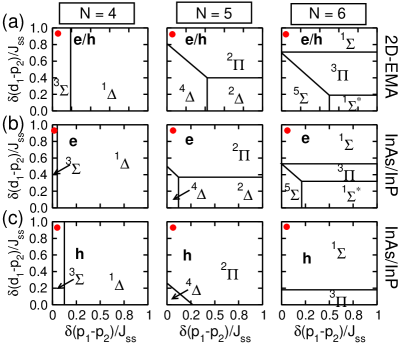
We further look at the filling orders of the electron/hole in the InAs/InP QDs. The filling orders of electrons and holes in QDs are determined by the following factors: He and Zunger (2006); He et al. (2005a) (i) the single-particle energy level spacing, (ii) the , energy level splittings and (iii) the Coulomb interactions. We adopt the general approaches in Refs. [He and Zunger, 2006; He et al., 2005a], and use the reduced single particle energy level spacing and to construct the phase diagrams of few carriers in QDs. Experimentally, the -orbit splitting in QDs can be measured via capacitance-voltage spectroscopy Reuter et al. (2005) or terahertz pump-probe method.Zibik et al. (2009)
For 4, 5, 6, the possible ground state configurations represented by the spectroscopic notation read as,He et al. (2005a)
| (12) | |||||
| (13) | |||||
| (14) | |||||
III.4.1 phase diagrams of electrons
The phase diagrams of electrons in InAs/InP QDs are presented in Fig. 10(b), contrast to those from two dimensional effective mass approximation (2D-EMA) calculations. The phase diagrams are determined by and . Previous calculationsGong et al. (2008) have shown that the electron levels in InAs/InP QDs have well defined electron structure, similar to those given by 2D-EMA. Therefore the phase diagram from 2D-EMA and atomistic model share quite similar features. The ground state configurations for = 4 - 6 are , , (indicated by the red spots in the figure), respectively, following Hund’s rule and Aufbau principle. However, for =4, the area allow stable configuration in InAs/InP QDs is much smaller than that of the 2D-EMA model.
III.4.2 phase diagrams of holes
The phase diagrams of holes in InAs/InP QDs are presented in Fig. 10(c). Unlike those of the InAs/GaAs QDs, the hole levels in InAs/InP QDs have well defined shell structure. The ground state of is , satisfying Hund’s rule. However, the phase diagrams of holes in the InAs/InP QDs still differ greatly than calculated by 2D-EMA for = 5, 6.
: The are three possible ground state configurations for 2D-EMA model and in InAs/GaAs QDs.He et al. (2005b) He et alHe et al. (2005b) have predicated that the non-Aufbau phase can be found for large in InAs/GaAs QDs. Similar phase, however, can not be found in InAs/InP QDs. This can be understood as following. In InAs/InP QDs, the -orbital splitting 1 - 4 meV and - level spacing 15 - 30 meV (see Fig. 2), so the Coulomb interactions between holes are not strong enough to overcome the - spacing in InAs/InP QDs. Therefore is always unfavorable in energy in InAs/InP dots.
: There are four possible ground state configurations for . In both InAs/GaAs and InAs/InP QDs, the can not be observed. However, there are still obvious difference between the filling orders in InAs/GaAs and InAs/InP QDs. In InAs/GaAs QDs,He et al. (2005b) the hole can be localized in the interface, resulting in extremely small level spacing between and orbits, hence the , which violate the Hund’s rule, is possible.He and Zunger (2006); He et al. (2005a); Ediger et al. (2007a) In InAs/InP QDs, only two phases, and , can be found.
The hole energy level spacings in InAs/InP QDs are significantly larger than in InAs/GaAs dots, and the level splittings are significantly smaller. Therefore, the ground states for =5, 6 in InAs/InP QDs are and respectively, as indicated by the red dots in Fig.2(c), which obey both Hund’s rule and Aufbau principle.
III.5 PL Spectra of highly charged excitons
Having clarified the ground state configurations and filling orders of electrons and holes in the InAs/InP QDs, we now turn to the PL spectra of highly charged excitons, which provides a useful tool to explore the complex interactions in the QDs.Ediger et al. (2007a) In InAs/GaAs QDs, it is found that the PL spectra of highly charged excitons exhibit some peculiar properties due to the breakdown of the Aufbau principle for hole.Ediger et al. (2007a)
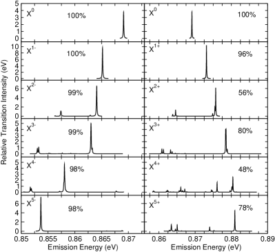
We present the calculated PL spectra of and ( = 0 - 5) for InAs/InP QDs in Fig. 11. We also calculated the PL spectra of highly charged InAs/GaAs QDs. The results (not shown) agree very well with previous calculations in Ref. [Ediger et al., 2007a]. There are several differences between the PL spectra of these InAs/InP and InAs/GaAs dots.
(i) The transition intensities of and in InAs/InP are weaker than that in InAs/GaAs QDs, due to the relatively longer lifetime in InAs/InP QDs. Rough estimation shows that the transition intensities in InAs/InP are half of those in InAs/GaAs QDs.
(ii) In InAs/InP QDs, the main peak of is on the lower energy side of by about 16 meV, and that of is on the higher energy side of by about 12 meV, much larger than the energy shifts in InAs/GaAs QDs, where both and are on the lower energy side of by about 10 meV and 2 meV respectively. These differences are due to the different confinement potentials of the two dots, as discussed in Sec. III.1.
(iii) The number in each panel is the overlap between the many-particle wave functions from CI calculations and those from Hartree-Fock approximations for the initial states, i.e.,
| (15) |
represents the percentage of the leading configurations in state . We find that there are significant differences of between and in InAs/InP QDs. For , is generally larger than 98%, in contrast to 95% in InAs/GaAs QDs. Moreover, the configuration hybridization of the final states of ( = 4, 5) is also much smaller than that in the InAs/GaAs QDs. Therefore, and have much fewer peaks in the InAs/InP PL spectra than in the InAs/GaAs spectraEdiger et al. (2007a). For , we find that the hybridization effect in InAs/InP is much stronger than that in InAs/GaAs QDs. For example, in InAs/InP QDs, = 56%, much smaller than 84% in InAs/GaAs QDs. This giant difference is from the smaller level energy splitting in InAs/InP QDs, as illustrated in Fig. 2. The strong hybridization effects lead to the much more complex PL spectra in InAs/InP QDs when 3.
(iv) In the InAs/GaAs QDs, holes may violate Hund’s rule and Afubau’s principle. For example, in the InAs/GaAs QDs, has a close shell ground state,Ediger et al. (2007a) and therefore no polarization dependent photoluminescence. In contrast, of InAs/InP QDs has a open shell ground state, and therefore has polarization dependent photoluminescence. Furthermore, there are many more transition peaks due to the spin splitting in the InAs/InP spectra than in the InAs/GaAs spectra. Previous calculations Ediger et al. (2007a) show that has open shell ground state and has polarization dependent photoluminescence in the InAs/GaAs QDs. However, in the InAs/InP QDs, has close shell ground state, and no polarization dependence in the photoluminescence. These differences reflect that the hole occupation in the two dots are significantly different.
IV Summary
In this work, we present a comprehensive studies of the optical properties of InAs/InP QDs using an empirical pseudopotential method and configuration interaction treatment of many-particle interactions. The results are contrast to those of InAs/GaAs QDs, whose properties are well understood, both theoretically and experimentally. The main difference between the optical properties of the two QDs can be summarized as: (i) The alignment of emission lines of neutral exciton, charged exciton and biexciton in InAs/InP QDs is quite different from that in InAs/GaAs QDs. (ii) The hidden correlation in InAs/InP QDs is about 0.7 - 0.9 meV, much smaller than that in InAs/GaAs QDs (1.2 - 2.2 meV). (iii) The lifetimes of neutral exciton, charged exciton and biexciton in InAs/InP QDs are about twice longer than those in InAs/GaAs QDs. (iv) The phase diagrams of electrons and holes in InAs/InP QDs differ greatly from those in InAs/GaAs QDs. The filling orders of electrons and holes are shown to obey the Hund’s rule and Aufbau principle. (vi) The PL spectra of highly charged excitons show some significant difference between the two dots, due to the different filling orders and Coulomb interactions between carriers.
Acknowledgements.
L.H. acknowledges support from the National Science Foundation of China under grants 60921091 and “Hundreds of Talents” program from Chinese Academy of Sciences.References
- Huffaker et al. (1998) D. L. Huffaker, G. Park, Z. Zou, O. B. Shchekin, and D. G. Deppe, Appl. Phys. Lett. 73, 2564 (1998).
- Djie et al. (2007) H. S. Djie, B. S. Ooi, X.-M. Fang, Y. Wu, J. M. Fastenau, W. K. Liu, and M. Hopkinson, Optics Letters 32, 44 (2007).
- Shields (2007) A. J. Shields, Nature Photonics 1, 215 (2007).
- Bonadeo et al. (2000) N. H. Bonadeo, J. Erland, D. Gammon, D. Park, D. S. Katzer, and D. G. Steel, Science 282, 1473 (2000).
- Xu et al. (2007a) X. Xu, B. Sun, P. R. Berman, D. G. Steel, A. S. Bracker, D. Gammon, and L. J. Sham, Science 317, 929 (2007a).
- Xu et al. (2007b) X. Xu, Y. Wu, B. Sun, Q. Huang, J. Cheng, D. G. Steel, A. S. Bracker, D. Gammon, C. Emary, and L. J. Sham, Phys. Rev. Lett. 99, 097401 (2007b).
- Atatüre et al. (2006) M. Atatüre, J. Dreiser, A. Badolato, A. Högele, K. Karrai, and A. Imamoglu, Science 312, 551 (2006).
- Michler et al. (2000) P. Michler, A. Kiraz, C. Becher, W. V. Schoenfeld, P. M. Petroff, L. Zhang, E. Hu, and A. Imamoğlu, Science 290, 2282 (2000).
- Imamoglu and Yamamoto (1994) A. Imamoglu and Y. Yamamoto, Phys. Rev. Lett. 72, 210 (1994).
- Yuan et al. (2002) Z. Yuan, B. E. Kardynal, R. M. Stevenson, and M. Pepper, Science 295, 102 (2002).
- Stevenson et al. (2006) R. M. Stevenson, R. J. Young, P. Atkinson, K. Cooper, D. A. Ritchie, and A. J. Shields, Nature 439, 179 (2006).
- Akopian et al. (2006) N. Akopian, N. H. Lindner, E. Poem, Y. Berlatzky, J. Avron, D. Gershoni, B. D. Gerardot, and P. M. Petroff, Phys. Rev. Lett. 96, 130501 (2006).
- Loss and DiVincenzo (1998) D. Loss and D. P. DiVincenzo, Phys. Rev. A 57, 120 (1998).
- Finley et al. (2001) J. J. Finley, P. W. Fry, A. D. Ashmore, A. Lemaitre, A. I. Tartakovskii, R. Oulton, D. J. Mowbray, M. S. Skolnick, M. Hopkinson, P. D. Buckle, et al., Phys. Rev. B 63, 161305 (2001).
- Ware et al. (2005) M. E. Ware, E. A. Stinaff, D. Gammon, M. F. Doty, A. S. Bracker, D. Gershoni, V. L. Korenev, S. C. Bǎdescu, Y. Lyanda-Geller, and T. L. Reinecke, Phys. Rev. Lett. 95, 177403 (2005).
- Gammon et al. (1996) D. Gammon, E. S. Snow, B. V. Shanabrook, D. S. Katzer, and D. Park, Phys. Rev. Lett. 76, 3005 (1996).
- Bayer et al. (2002) M. Bayer, G. Ortner, O. Stern, A. Kuther, A. A. Gorbunov, A. Forche, P. Hawrylak, S. Fafard, K. Hinzer, T. L. Reinecke, et al., Phys. Rev. B 65, 195315 (2002).
- Bayer and Forche (2003) M. Bayer and A. Forche, Phys. Rev. B 65, 041308 (2003).
- Reuter et al. (2005) D. Reuter, P. Kailuweit, A. D. Wieck, U. Zeitler, O. Wibbelhoff, C. Meier, A. Lorke, and J. C. Maan, Phys. Rev. Lett. 94, 026808 (2005).
- Fonseca et al. (1998) L. R. C. Fonseca, J. L. Jimenez, J. P. Leburton, and R. M. Martin, Phys. Rev. B 57, 4017 (1998).
- Bock et al. (2002) C. Bock, K. H. Schmidt, U. Kunze, V. V. Khorenko, S. Malzer, and G. H. Döhler, Physica E 13, 208 (2002).
- Stier et al. (1999) O. Stier, M. Grundmann, and D. Bimberg, Phys. Rev. B 59, 5688 (1999).
- Williamson and Zunger (1999) A. J. Williamson and A. Zunger, Phys. Rev. B 59, 15819 (1999).
- Wang et al. (1999) L.-W. Wang, J. Kim, and A. Zunger, Phys. Rev. B 59, 5678 (1999).
- Williamson et al. (2000) A. J. Williamson, L.-W. Wang, and A. Zunger, Phys. Rev. B 62, 12963 (2000).
- Williamson et al. (2001) A. J. Williamson, A. Franceschetti, and A. Zunger, Europhys. Lett. 53, 59 (2001).
- He et al. (2004) L. He, G. Bester, and A. Zunger, Phys. Rev. B 70, 235316 (2004).
- Reithmaier et al. (2004) J. P. Reithmaier, G. S. ogonk, A. Löffler, C. Hofmann, S. Kuhn, S. Reitzenstein, L. V. Keldysh, V. D. Kulakovskii, T. L. Reinecke, and A. Forchel, Nature 432, 197 (2004).
- Yoshie et al. (2004) T. Yoshie, A. Scherer, J. Hendrickson, G. Khitrova, H. M. Gibbs, G. Rupper, C. Ell, O. B. Shchekin, and D. G. Deppe, 432, 200 (2004).
- Hennessy et al. (2007) K. Hennessy, A. Badolato, M. Winger, D. Gerace, M. Atatüre, S. Gulde, S. Fält, E. L. Hu, and A. Imamoǧlu, Nature 445, 896 (2007).
- Kamada et al. (2001) H. Kamada, H. Gotoh, J. Temmyo, T. Takagahara, , and H. Ando, Phys. Rev. Lett. 87, 246401 (2001).
- Zrenner et al. (2002) A. Zrenner, E. Beham, S. Stufler, F. Findeis, M. Bichler, and G. Abstreiter, Nature 418, 612 (2002).
- Stievater et al. (2001) T. H. Stievater, X. Li, D. G. Steel, D. Gammon, D. S. Katzer, D. Park, C. Piermarocchi, and L. J. Sham, Phys. Rev. Lett. 87, 133603 (2001).
- Emary et al. (2007) C. Emary, X. Xu, D. G. Steel, S. Saikin, and L. J. Sham, Phys. Rev. Lett. 98, 047401 (2007).
- Ramsay et al. (2008) A. J. Ramsay, S. J. Boyle, R. S. Kolodka, J. B. B. Oliveira, J. Skiba-Szymanska, H. Y. Liu, M. Hopkinson, A. M. Fox, and M. S. Skolnick, Phys. Rev. Lett. 100 (2008).
- Bahder (1990) T. B. Bahder, Phys. Rev. B 41, 11992 (1990).
- Nakaoka et al. (2004) T. Nakaoka, T. Saito, J. Tatebayashi, and Y. Arakawa, Phys. Rev. B 70, 235337 (2004).
- Pryor (1998) G. Pryor, Phys. Rev. B 57, 7190 (1998).
- Pryor (1999) C. Pryor, Phys. Rev. B 60, 2869 (1999).
- Pryor et al. (1997) C. Pryor, M.-E. Pistol, and L. Samuelson, Phys. Rev. B 56, 10404 (1997).
- Wang and Zunger (1999) L.-W. Wang and A. Zunger, Phys. Rev. B 59, 15806 (1999).
- Bryant and Jaskolski (2003) G. Bryant and W. Jaskolski, Phys. Rev. B 67, 205320 (2003).
- Gong et al. (2004) Q. Gong, R. Nötzel, P. J. van Veldhoven, T. J. Eijkemans, and J. H. Wolter, Appl. Phys. Lett. 84, 275 (2004).
- Caroff et al. (2005) P. Caroff, C. Paranthoen, C. Platz, O. Dehaese, H. Folliot, N. Bertru, C. Labbé, R. Piron, E. Homeyer, A. L. Corre, et al., Appl. Phys. Lett. 87, 243107 (2005).
- Kim et al. (2009) D. Kim, W. Sheng, P. J. Poole, D. Dalacu, J. Lefebvre, J. Lapointe, M. E. Reimer, G. C. Aers, and R. L. Williams, Phys. Rev. B 79, 045310 (2009).
- Reimer et al. (2009) M. E. Reimer, D. Dalacu, J. Lapointe, P. J. Poole, D. Kim, G. C. Aers, W. R. McKinnon, and R. L. Williams, Appl. Phys. Lett. 94, 011108 (2009).
- Cornet et al. (2006) C. Cornet, A. Schliwa, J. Even, F. Doré, C. Celebi, A. Létoublon, E. Macé, C. Paranth’́oem, A. Simon, P. M. Koenraad, et al., Phys. Rev. B 74, 035312 (2006).
- Gong et al. (2008) M. Gong, K. Duan, C. Li, R. Magri, G. A. Narvaez, and L. He, Phys. Rev. B 77, 045326 (2008).
- He et al. (2008) L. He, M. Gong, C.-F. Li, G.-C. Guo, and A. Zunger, Phys. Rev. Lett. 101, 157405 (2008).
- Sasakura et al. (2009) H. Sasakura, H. Kumano, I. Suemune, J. Motohisa, Y. Kobayashi, M. van Kouwen, K. Tomioka, T. Fukui, N. Akopian, and V. Zwiller, Journal of Physics Conference Series 193 (2009).
- Ediger et al. (2005) M. Ediger, P. A. Dalgarno, J. M. Smith, B. D. Gerardot, and R. J. Warburton, Appl. Phys. Lett. 86, 211909 (2005).
- Ediger et al. (2007a) M. Ediger, G. Bester, A. Badolato, P. M. Petroff, K. Karrai, A. Zunger, and R. J. Warburton, Nature Physics 3, 774 (2007a).
- Bester (2009) G. Bester, J. Phys.: Condens. Matter 21, 023202 (2009).
- Keating (1966) P. N. Keating, Phys. Rev 145, 637 (1966).
- Martin (1970) R. M. Martin, Phys. Rev. B 1, 4005 (1970).
- Bester and Zunger (2005) G. Bester and A. Zunger, Phys. Rev. B 71, 045318 (2005).
- Franceschetti et al. (1999) A. Franceschetti, H. Fu, L.-W. Wang, and A. Zunger, Phys. Rev. B 60, 1819 (1999).
- Franceschetti and Zunger (2000) A. Franceschetti and A. Zunger, Europhys. Lett. 50, 243 (2000).
- Ediger et al. (2007b) M. Ediger, G. Bester, B. D. Gerardot, A. Badolato, P. M. Petroff, K. Karrai, A. Zunger, and R. J. Warburton, Phys. Rev. Lett. 98, 036808 (2007b).
- Ding et al. (2010) F. Ding, R. Singh, J. D. Plumhof, T. Zander, V. Kiapek, Y. H. Chen, M. Benyoucef, V. Zwiller, K. Dörr, G. Bester, et al., Phys. Rev. Lett. 104, 067405 (2010).
- Warming et al. (2009) T. Warming, E. Siebert, A. Schliwa, E. Stock, R. Zimmermann, and D. Bimberg, Phys. Rev. B 79, 125316 (2009).
- Siebert et al. (2009) E. Siebert, T. Warming, A. Schliwa, M. Winkelnkemper, S. Rodt, and D. Bimberg, Phys. Rev. B 79, 205321 (2009).
- Dalgarno et al. (2008) P. A. Dalgarno, J. M. Smith, J. McFarlane, B. D. Gerardot, K. Karrai, A. Badolato, P. M. Petroff, and R. J. Warburton, Phys. Rev. B 77, 245311 (2008).
- Rodt et al. (2005) S. Rodt, A. Schliwa, K. Pötschke, F. Guffarth, and D. Bimberg, Phys. Rev. B 71, 155325 (2005).
- Narvaez et al. (2005a) G. A. Narvaez, G. Bester, and A. Zunger, Phys. Rev. B 72, 041307 (2005a).
- Narvaez et al. (2005b) G. A. Narvaez, G. Bester, and A. Zunger, Phys. Rev. B 72, 245318 (2005b).
- Bester and Zunger (2003) G. Bester and A. Zunger, Phys. Rev. B 68, 073309 (2003).
- Avron et al. (2008) J. E. Avron, G. Bisker, D. Gershoni, N. H. Lindner, E. A. Meirom, and R. J. Warburton, Phys. Rev. Lett. 100, 120501 (2008).
- (69) W. W. Zhang, M. Gong, C. F. Li, G. C. Guo, and L. X. He, to be published.
- Thränhardt et al. (2002) A. Thränhardt, C. Ell, G. Khitrova, and H. M. Gibbs, Phys. Rev. B 65, 035327 (2002).
- Drexler et al. (1994) H. Drexler, D. Leonard, W. Hansen, J. P. Kotthaus, and P. M. Petroff, Phys. Rev. Lett. 73, 2252 (1994).
- He and Zunger (2006) L. He and A. Zunger, Phys. Rev. B 73, 115324 (2006).
- He et al. (2005a) L. He, G. Bester, and A. Zunger, Phys. Rev. Lett. 95, 246804 (2005a).
- Zibik et al. (2009) E. A. Zibik, T. Grange, B. A. Carpenter, N. E. Porter, R. Ferreira, G. Bastard, D. Stehr, S. Winnerl, M. Helm, H. Y. Liu, et al., Nature Materials 8 (2009).
- He et al. (2005b) L. He, G. Bester, and A. Zunger, Phys. Rev. Lett. 94, 016801 (2005b).