Artificial photosynthetic reaction centers coupled to light-harvesting antennas
Abstract
We analyze a theoretical model for energy and electron transfer in an artificial photosynthetic system. The photosystem consists of a molecular triad (i.e., with a donor, a photosensitive unit, and an acceptor) coupled to four accessory light-harvesting antennas pigments. The excitation energy transfer from the antennas to the artificial reaction center (the molecular triad) is here described by the Förster mechanism. We consider two different kinds of arrangements of the accessory light-harvesting pigments around the reaction center. The first arrangement allows direct excitation transfer to the reaction center from all the surrounding pigments. The second configuration transmits energy via a cascade mechanism along a chain of light-harvesting chromophores, where only one chromophore is connected to the reaction center. At first sight, it would appear that the star-shaped configuration, with all the antennas directly coupled to the photosensitive center, would be more efficient. However, we show that the artificial photosynthetic system using the cascade energy transfer absorbs photons in a broader wavelength range and converts their energy into electricity with a higher efficiency than the system based on direct couplings between all the antenna chromophores and the reaction center.
I Introduction
The reaction centers of natural photosystems are surrounded by a number of accessory light-harvesting complexes Alberts . These light-harvesting antennas absorb sunlight photons and deliver their excitation energy to the reaction center, which creates a charge-separated state. The photosystem of green plants is made up of six photosynthetic accessory pigments: carotene, xanthophyll, phaeophytin , phaeophytin , chlorophyll , and chlorophyll Alberts . Each pigment absorbs light in a different range of the solar spectrum. As a result, the antenna complex significantly increases the effective frequency range for the light absorption, resulting in a highly-efficient photocurrent generation. In the presence of excessive sunlight the antenna complex can reversibly switch to the photo-protected mode, where harmful light energy is dissipated.
The efficient performance of natural photosystems motivates researchers to mimic their functions by creating photosynthetic units, which are combined to antenna complexes with artificial reaction centers. For example, a light-harvesting array of metalated porphyrins has been developed in Ref. gust1 . This array absorbs light and rapidly transfers the excitation energy to the reaction center, so that the porphyrin (P)–fullerene (C60) charge-separated state, P+–C, is formed with a quantum yield . Mixed self-assembled monolayers of the ferrocene (Fc)–porphyrin–fullerene molecular triad and the boron dipyrrin (B) dye have been made in Ref. imahori1 ; imahoriR with the goal to examine both energy and electron transfers in the artificial reaction center (Fc–P–C60), coupled to the light-harvesting molecule B. A quantum yield of for photocurrent production at the wavelength 510 nm and a quantum yield of at the wavelength 430 nm have been reported imahori1 .
Recently, a more efficient, sophisticated and rigid antenna-reaction system has been designed in Refs. gust2 ; gust3 . This system includes three kinds of light-absorbing chromophores: (i) bis (phenylethynyl)anthracene (BPEA), which absorbs around 450 nm wavelength (blue region); (ii) borondipyrromethene (BDPY), having a strong absorption at 513 nm (green region); and (iii) zinc tetraarylporphyrin, which absorbs both at 418 nm and at 598 nm. This study reports 100 quantum yield for the excitation transfer and 95 quantum yield for the generation of the charge-separated state P+–C.
Energy transfer mechanisms in the multi-chromophoric light-harvesting complexes of bacterial photosystems (e.g., excitation-transfer between chlorophyll molecules in the Fenna-Matthews-Olson (FMO) protein complex) have been studied elsewhere (see, e.g., Ref. fleming1 ; Gilmore ; Alan ; yang ). Those works fleming1 ; Gilmore ; Alan ; yang have mainly focused on the quantum effects in excitation-transfer across the bacteriochlorophyll units.
Theoretical studies of antenna-reaction center complexes can be useful for a better understanding of, and for optimizing light-to-electricity conversion, as well as for developing new and efficient designs of solar cells. Recently we have theoretically analyzed JPCc09 the light-to-electricity energy conversion in a molecular triad (Fc–P–C60) electronically coupled to conducting leads. It was shown that the Fc–P–C60 triad can transform light energy into electricity with a power-conversion efficiency of order of 40%, provided that the connection of the triad to the leads is strong enough. It should be noted, however, that this prototype solar cell absorbs photons with energies in close proximity to the resonant transition of the central porphyrin molecule. Therefore, a major fraction of the sunlight spectrum is not converted to the electrical form by this device.
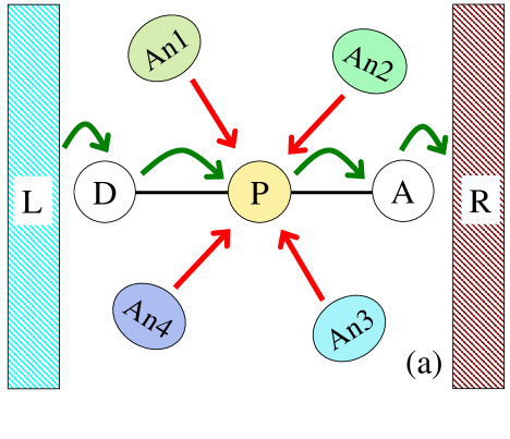
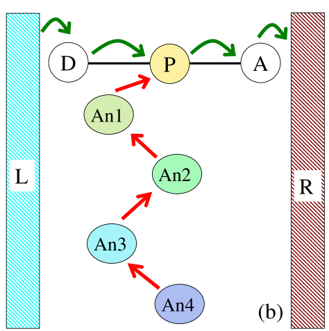
In this paper we examine a theoretical model for the light-to-electricity energy conversion by a molecular triad, which is surrounded by four additional light-harvesting antenna complexes. We show that this artificial photosystem is able to generate a photocurrent with a quantum yield of the order of 90 % (when the reorganization energy for the Förster transfer is relatively high) absorbing photons in a wide range (420–670 nm) of the solar spectrum. We consider two different configurations for the antenna complexes: (a) where each light-harvesting molecule is independently connected (by the Förster energy-transfer mechanism) to the central porphyrin (P) molecule of the triad (Fig. 1a); and (b) where the light-harvesting molecules are arranged in a line (Fig. 1b), with only one molecule directly coupled to the porphyrin and with other molecules forming a chain where the energy propagates in a cascade-manner.
Let us consider a (D-P-A) reaction center surrounded by several (say, four) accessory light-harvesting antennas. Which is the best way to arrange in space these accessory antennas? In other words, which network or topology would provide more energy from the surrounding accessory antennas to the central reaction center? A star-shaped configuration? (with each accessory antenna directly coupled to the central reaction center). Or in a somewhat opposite configuration: as a linear chain with nearest-neighboring couplings between the antennas and only one of these coupled to the reaction center? These two cases are shown in Fig. 1.
In principle, very many possible topologies could be considered. However, to simplify this analysis, we will now focus on two extreme cases, with somewhat opposite topologies or networks: a well-connected reaction center (directly connected to all four accessory light harvesting antennas), and the opposite case where the central reaction center is coupled to only one antenna, which is now part of a linear chain. These two extreme-opposite topologies or networks can be denoted as star-shaped (shown in Fig. 1a) and linear-chain (Fig. 1b), respectively.
At first sight, it would seem that the star-shaped configuration, with each antenna directly connected to the reaction center, can provide far more energy to the reaction center, due to the multiple connections between the central unit, and the surrounding antennas. However, an energy bottleneck can arise even in this apparently-optimal topological configuration. Each antenna is here assumed to operate optimally in a limited, and shifted, frequency range. In other words, we are not assuming all accessory light-harvesting antennas to be equal to each other. In general, various antennas can operate in different frequency ranges, and this difference is crucial in our analysis. Recall that the photosystem of green plants is made of six light-harvesting accessory pigments: each pigment absorbing light in a different range of the solar spectrum. Thus, in the star-shaped topology shown in Fig. 1a, antennas with a large energy mismatch would not provide energy to the central reaction center. Only the surrounding accessory antennas that have an approximate energy match to the central reaction center would transfer energy. This energy bottleneck works against the star-shaped network shown in (a).
Thus, the two issues considered here are: (1) how to physically arrange antennas around the central reaction center, and also (2) how to arrange these in energy-space, so to speak. The first issue is topological and focuses on the network connectivity in real space: for instance, how many accessory antennas are connected to a central reaction center. The second issue refers to the energy match (or mismatch) between neighboring antennas, and between them and the central reaction center. A large energy mismatch between any connected units in the chain would preclude energy transfer between them. This approximate “energy matching” issue between neighboring units is equally important to keep in mind, not just the real-space topological arrangement of the units.
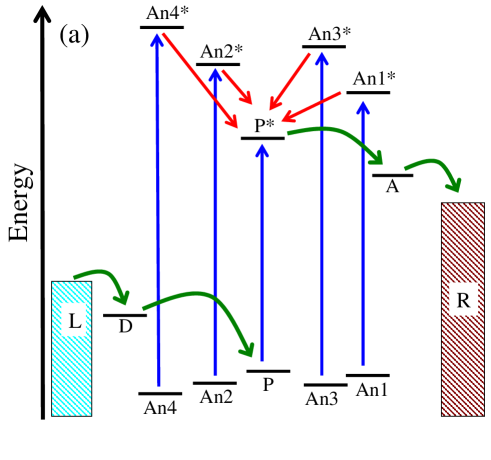
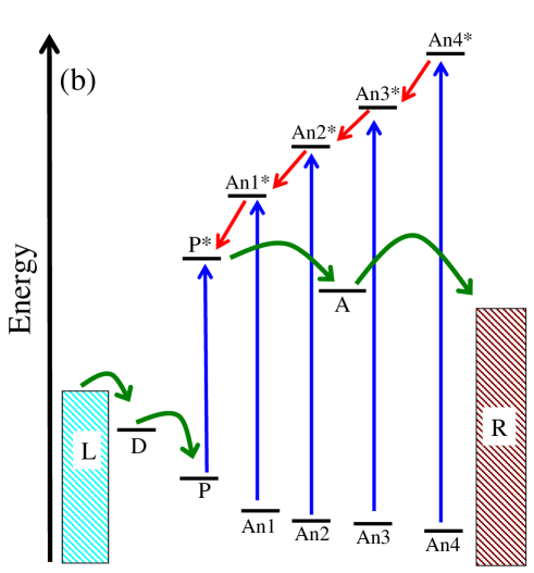
As mentioned above, Fig. 1 shows the connectivity between the different units: star-shaped topology in (a), and linear-chain configuration in (b). Moreover, the colors there represent, very schematically, the energy range where each unit operates optimally. The linear chain shown there has antennas arranged in a way that nearby units operate in approximately similar energy ranges. This energy-matching issue perhaps is not very clear in Fig. 1, even when seen in color. The energy scales are shown far more explicitly in Fig. 2. Figure 2b clearly shows that the linear chain model considered here operates via an energy cascade, or linear chain-reaction. Like a line of falling dominoes, one event triggering the next one, in a sequential manner, with small energy mismatches between successive energy transfer events. As shown in Fig. 2b, the more energetic antenna is located far away from the reaction center, and it is coupled to an antenna with a slightly lower energy, which is coupled to another antenna with an even slightly lower energy, and so on, moving energetically “downhill” along the chain. Thus, the neighboring antennas must be so both in real space, and also in “energy space”, to allow for the efficient transfer of energy between them. Thus, “proximity” between units must be in two spaces: real space and energy space.
This article is organized as follows: in Section II we outline a model for the artificial reaction center (molecular triad) coupled to the antenna complex. We briefly describe our mathematical methods in Sec. III. The parameters are listed in Sec. IV. In Sec. V, we numerically solve the master equations and analyze the energy transfer process. Conclusions are presented in Sec. VI. The methods used are described in more details in the online supplementary material.
II Model
We start with a schematic description of the energy and electron transfer processes in an artificial reaction center D–P–A (Donor–Porphyrin–Acceptor) combined with four antenna chromophores: An1, An2, An3, An4 (see Figs. 1a and 1b, showing two different configurations for these antennas: star-shaped configuration in 1a and chain in 1b). The photosensitive molecular triad, D–P–A, is inserted between two electron reservoirs (electrodes) L and R. The donor, D, is coupled to the left lead, L, and the acceptor, A, is connected to the right lead, R. As in Refs. imahori1 ; JPCc09 , the donor and acceptor molecules (e.g., ferrocene and fullerene), are connected to each other via the photosensitive molecule (porphyrin, P). This molecule is surrounded by four Accessory Light-Harvesting Pigments (ALHP). Figure 1a corresponds to the situation where all pigments are directly coupled to the photosensitive part (P) of the molecular triad. In this “star-shaped” geometric arrangement, all the ALHP can directly transfer excitations to the photosensitive part of the molecular triad. Figure 1b corresponds to the case where the light-harvesting pigments form a chain, which transfers energy where the excitation moves from one pigment to the next one via nearest-neighbor couplings: An4 An3 An2 An1 P. This cascade-like excitation transfer occurs in an energetically-downhill direction, akin a one-dimensional chain reaction or domino-effect.
Figures 2a and 2b present the energy diagrams of the photosystems described in Figs. 1a and 1b, respectively. The electron transfer chain, LDP PAR, is the same for both configurations (a) and (b), and both begin on the left lead, L. The electrochemical potentials of the left (L) and right (R) electron reservoirs are determined by the parameters and , with Since the energy level of the donor D is lower than the potential of the left lead, , electrons can move from the L-reservoir to the level D and, afterwards, to the low-lying ground energy level, , of the porphyrin. When absorbing a photon, the electron in the porphyrin molecule jumps from its ground state P to its excited state P∗. A subsequent electron transfer from P∗ to the acceptor A is driven by a negative energy gradient, . In view of the relation: the electron in A is finally transferred to the right, R, electron reservoir. This is the light-induced electron transition in the porphyrin molecule, which results in an energetically-uphill electron flow in both photosynthetic systems (a) and (b).
Even though these systems (a) and (b) have the similar electron-transport chains, their light-harvesting complexes are arranged quite differently. Each of these complexes, An = An1, , An4, can be characterized by a ground, , and an excited, energy levels with an energy difference . Hereafter, we assume that and . For the light-harvesting complex (a) (see Figs. 1a, 2a) all frequencies should exceed the porphyrin transition frequency, In this case the energy of photons collected by each individual antenna can be transferred directly to the photosensitive part of the artificial reaction center (porphyrin molecule). However, in the light-harvesting complex (b) (see Figs. 1b and 2b) only the antenna An1 is coupled (by a Förster mechanism) to the porphyrin, whereas the other light-harvesting pigments form a linear chain that transfers energy downhill along the chain: An4 An3 An2 An1 P. This energy transfer can be energetically-allowed provided that In Sec. V we compare these two artificial photosystems and determine which arrangement of the antenna complexes provides more energy to the reaction center.
III Methods
The electron flow through a molecular triad coupled to two electron reservoirs can be described with methods of quantum transport theory and the theory of open quantum systems Wingr93 ; MarcusSutin ; JCP09CcO ; JCP09Photo . In addition to four sites (D, P, P∗, A), describing the molecular triad, we introduce four pairs (An1, An1∗, , An4, An4∗), which characterize the ground and excited states of the light-harvesting antennas. The whole system, the molecular triad plus four antenna complexes, can be analyzed within a mathematical formalism presented in Supporting Information and also in Ref. JPCc09 .
The total Hamiltonian of the system includes the following components:
(i) energies of the electron sites and leads, as well as the Coulomb interactions between the electrons located on different sites of the triad;
(ii) tunneling couplings between the electron sites on the triad and the electron reservoirs;
(iii) electron tunneling between the electron sites belonging to the molecular triad;
(iv) coupling of electron sites and antenna complexes to an environment;
(v) interactions of the porphyrin molecule and antenna complexes with an external electromagnetic field (laser field) and with
(vi) blackbody radiation and Ohmic bath, responsible for the quenching (energy loss) of the porphyrin and antenna excited states.
(vii) In the case of the design in Fig. 1a the Hamiltonian includes the direct Förster coupling between the porphyrin molecule, P, and the light-harvesting complexes An1, , An4. For the linear-chain configuration shown in Fig. 1b, the Förster mechanism provides the energy transfer between the nearest-neighbors in the antenna chain, as well as between the complex An1 and the porphyrin molecule.
IV Parameters
Energy levels and electrochemical potentials: The energy levels of the Fc–P–C60 molecular triad are meV, meV, meV and meV. These values are obtained by estimating the reduction potentials (using a reference electrode Ag/AgCl) of ferrocene (D), porphyrin (P, P∗) and fullerene (A) molecules JPCB2000 . For the electrochemical potentials of the left () and the right () leads, we choose the following values: meV and meV, with the electrochemical gradient meV.
Coulomb interactions: The spatial separations between D–P, P–A and D–A are of order of 1.62 nm, 1.8 nm and 3.42 nm, respectively JPCB2000 . The Coulomb energies , and can be calculated with the formula
where, and is the vacuum dielectric constant. For , the Coulomb interaction energies are meV, meV and meV.
The Förster coupling, , between the photosensitive molecules and is proportional to the product of the dipole moments of these molecules, and , and inversely proportional to the cubic power of the distance () between them PumpPRE08 :
| (1) |
For the case where 0.3 nm, 1 nm, and at 4, the Förster coupling is about 65 meV.
Tunneling amplitudes: We have assumed the ferrocene–porphyrin and porphyrin–fullerene tunneling amplitudes are about 3 meV, so that
For the tunneling rates between the left lead and ferrocene () and between the right lead and fullerene () we choose the following values JPCc09 : = 1800 s-1 and = 180 s-1.
Radiation leakage and quenching rates: We take the following estimates for the radiation leakage time: ns. Similar estimates have been used for the radiation leakage timescales of the antenna molecules. For the quenching (or energy-loss) time of the porphyrin excited state P∗ we use the value: ns.
Reorganization energies for the electron and energy transfers: For the molecular triad analyzed in Ref. JPCc09 we obtain the relatively high power-conversion efficiency, provided that the donor-porphyrin and acceptor-porphyrin electron transfer reorganization energies are about meV and meV. A much smaller value, meV, is assumed for the light-induced electron transitions between the ground (P) and excited (P∗) levels of the porphyrin molecule. The Förster energy transfer between the light-harvesting molecules and between these molecules and the porphyrin is also accompanied by an environment-reorganization process, which can be characterized by a smaller energy scale, meV (see, e.g., the energy transfer in the B850 complex B850 , where is assumed to be about 30 meV).
Hereafter, we assume that the external light source has a fixed intensity, mW/cm2, and that the environment is kept at the room temperature, K. We also assume that the reorganization energy for the Förster energy transfer, is about 100 meV, unless otherwise specified.
We analyze the Fc–P–C60 molecular triad, where the ferrocene molecule, Fc, is attached to the gold surface (left lead, L), and the fullerene, C60, is in contact with an electrolyte solution (right lead, R) filled with oxygen molecules, which are able to accept electrons from the C60 molecules.
V Results and Discussion
We derive and solve numerically a set of master equations for the probabilities to find the system in a definite eigenstate of the basis Hamiltonian. This is explained in the online supplementary material. After that, we calculate: (i) the energetically-uphill electron current through the triad, (ii) the energy of the photons absorbed by the triad and by the light-harvesting molecules. This allows us to determine a quantum yield and power-conversion efficiency of the system (see all definitions in the supporting information).
V.1 Photocurrent through the molecular triad directly coupled to four porphyrin light-harvesting molecules
Here we consider the situation where both the reaction center and the antenna complexes are made of porphyrin molecules with the geometrical arrangement shown in Fig. 1a. This arrangement allows direct energy transfer from each light-harvesting chromophore to the reaction center.
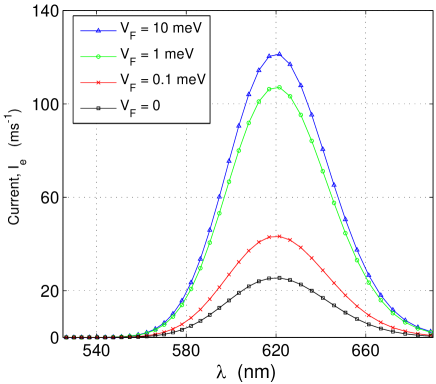
In Fig. 3 we plot the photocurrent through the triad as a function of the wavelength of light for different values of the Förster coupling strength : (in meV) and for the above-mentioned set of parameters of the system. It is apparent from Fig. 3 that the magnitude of the light-induced pumping current at nm is significantly enhanced (about 5 times larger when meV) by the antenna system. However, the spectral range of the light absorption remains the same as for the detached porphyrin reaction center (see Fig. 3, where the red curve with square symbols describes the photocurrent through the molecular triad completely disconnected from the antenna chromophores, ). We also find that the quantum yield, , taken in the middle of the resonant peak ( nm), non-monotonically depends on the Förster coupling strength measured here in meV: and
V.2 Molecular triad connected to two BPEA and two BDPY chromophores
Now we consider a different case: an antenna system comprised of two BDPY and two BPEA molecules. The BDPY molecule has the maximum absorbance in the green region (at 513 nm) of the solar spectrum, where neither BPEA (with maximum absorbance at 450 nm) nor the porphyrin, which absorbs at 620 nm, have maxima of absorption spectra. It should be noted that a multichromophoric hexad antenna system having three light-absorbing BDPY, BPEA and porphyrin has been developed in Ref. gust2 . The generation of the charge-separated state, P+–C, with almost 95 quantum yield gust2 . In our case, the porphyrin unit of the molecular triad is coupled to the four antenna chromophores (two BDPY and two BPEA).
We consider two situations: (a) where the antenna chromophores are directly coupled to the porphyrin unit of the reaction center (Fig. 1a); and (b) where the antenna chromophores are arranged in line: BDPY BDPY BPEA BPEA RC, with the nearest-neighbor coupling between chromophores. See Fig. 1b. Thus, the configuration (a) might appear to be energetically more efficient than (b). However, our calculations below indicate that this is not the case.
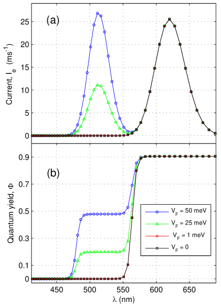
(a) For the case of direct connection between the four antennas chromophores and the triad (see Fig. 1a and Fig. 4) we calculate a photocurrent and a quantum yield, , as functions of the wavelength of light, at meV, and at five values of the Förster coupling: meV. The wavelength dependence of the current has two maxima centered at 513 nm and 620 nm. The BPEA molecules, which absorb at 450 nm, give a negligible contribution to the current since their spectral maxima are too far from the absorbance maximum of the porphyrin spectrum. As a consequence, the BPEA-porphyrin energy transfer is significantly suppressed at moderate values of the Förster reorganization energy, meV in the range of the coupling constants meV. It follows from Fig. 4 (see a peak at nm) that the BDPY molecules start working as efficient light-harvesters only at sufficiently strong Förster coupling, meV, to the porphyrin unit of the molecular triad. We also note that when nm, both the photoinduced current and the quantum yield grow with increasing the Förster coupling strength, so that the quantum yield, , can be around 48%. In the range of porphyrin absorption (at nm and ) the quantum yield is of the order of 90.
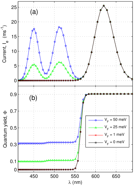
(b) A much broader light spectrum can be converted into electrical current in the linear configuration in Fig. 1b, where the light-harvesting chromophores are arranged along a line: BPEA BPEA BDPY BDPY RC, with the only one BDPY molecule directly coupled to the porphyrin unit of our artificial reaction center (RC) (see Fig. 1b and Fig. 5). This system is able to collect photons in the range of wavelength from 420 nm up to 650 nm covering a significant part of the visible sunlight spectrum. The chain of BPEA and BDPY molecules creates an efficient channel, which gradually transmits energy from the collectors of high-energy photons (BPEA molecules), via the intermediate BDPY antennas, to the molecular triad. In Figs. 5a, 5b we plot the photoinduced current and the quantum yield versus the wavelength of the external radiation, at meV, and at four values of the Förster constants (in meV) For large value of the Förster coupling strength the quantum yield reaches 48% in Fig.4(a) around 513 nm [for the star-shaped topology in Fig. 1a] and 30% in Fig. 5(b) [for the linear chain case in Fig 1b]. The quantum yield in Fig. 5b is lower than the one in Fig. 4a, but extends over a wider range of wavelengths including the peaks around 450 nm and 513 nm.
It follows from Fig. 4 and Fig. 5, that the configuration using the chain-like nearest-neighbor coupling between light-harvesting chromophores [Fig. 1b, design (b)] converts much more blue ( nm) light into electricity with a higher quantum yield than the star-shaped configuration with direct coupling between the antenna chromophores and the RC [Fig. 1a, design (a)]. In this star-shaped configuration, the BPEA molecules, which collects blue photons, are not able to transfer their energy to the photosensitive unit of the triad due to a significant difference between the energies of the BPEA antennas ( nm) and the porphyrin-based reaction center ( nm).
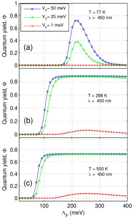
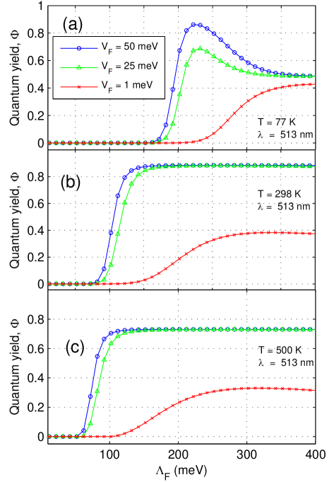
The antenna-RC energy transfer is facilitated by the strong coupling to the environment (when the energy difference is high), characterized by the reorganization energy , as well as by a tight Förster binding between chromophores, which is described by the constant . In Figs. 6 and 7 we plot the quantum yield, , as a function of the reorganization energy, , for three different temperatures (in K): = 77, 298, 500, and for three values of the coupling constant and 50 meV. Figure 6 is related to the blue peak of the absorption spectrum ( nm), whereas figures 7 describes the behavior of the green peak ( nm). The peak centered at nm is produced by the porphyrin molecule, belonging to the triad, and, therefore, shows no dependence on and .
The Marcus rates, describing the energy transmission between the photosensitive elements of the system, depend (i) on the energy difference, , between the photosensitive units, (ii) on the Förster coupling , and (iii) on the Förster reorganization energy . The large energy separation, , of the energies of the nearby photosensitive molecules leads to a decrease of the Marcus rates and, thus, to the suppression of the energy transfer. In our case, the energy distance between the BPEA ( = 450 nm) and BDPY ( = 513 nm) molecules is about 340 meV, whereas the energy separation of the BDPY chromophore and porphyrin ( = 620 nm) is of order of 415 meV. This energy gap can be partially compensated by the large reorganization energy, , which reflects the significant fluctuations of the relative positions of the energy levels. Here, the environment plays a positive role assisting the efficient and fast energy transfer between chromophores (see also Ref. Plenio ; Aspuru08 ). The timescales for the energy and electron transfers should be shorter than the radiation leakage time and the quenching time, otherwise the energy of the photons absorbed by the system will be lost.
At very low temperatures (e.g., liquid nitrogen, = 77 K), the fluctuations in the positions of the energy levels of the chromophores are frozen, so that the light-to-electricity conversion requires sufficiently large values of the reorganization energy, meV (see Figs. 6a and 7a). Note that for meV the linear-chain arrangement system has an optimal performance at meV for both frequency ranges. This extreme low temperature case is only shown for comparison with the higher temperatures cases.
At room temperature ( = 298 K) and at strong enough Förster coupling, meV, the blue and green spectral peaks demonstrate similar behaviors as functions of (see Figs. 6b and 7b). Here, the quantum yield begins to grow when the reorganization energy exceeds meV, reaching finally 90% at meV. These numbers are determined by the parameters of the antenna-triad complex, and, especially, by the radiation leakage time , of the excited porphyrin state P∗, estimated above as ns.
At high temperatures (see Figs. 6c and 7c, plotted for = 500 K) the facilitating effect of the environment increases, and the efficient energy transfer starts at the lower reorganization energies, meV. This value of is comparable with the reorganization energy for the energy transfer in the B850 light-harvesting complex, where meV B850 .
At the smaller value of the Förster coupling, meV, the conversion of the blue light ( = 450 nm) to electricity is significantly suppressed (see Fig. 6), whereas for green light ( = 513 nm) the dependence of the quantum yield on are shifted to higher reorganization energies (Fig. 7), compared to the case of the larger couplings, meV.
It should be noted that, to cover a broader range of the spectrum of light with a fixed number of antenna chromophores, the resonance energies of the light-harvesting complexes should be very well separated. However, in this case the energy transfer between the antenna chromophores would be quite slow, since this transfer is governed by the rates corresponding to the inverted regions of the Marcus parabola. Then, the dissipation comes into play, and the energy of the absorbed photons is lost on its way from the antennas to the reaction center. The energy transfer rates and, thus, the efficiency of the system can be maximized in the case when the energy distance, between the nearby light-harvesting complexes (labeled by indices and , with energies and ) is equal to the corresponding reorganization energy, . That is,
VI Conclusions
In this paper we have studied theoretical aspects of the operation of an artificial reaction center (a ferrocene–porphyrin–fullerene molecular triad) coupled to the complex of four light-harvesting molecules. We have analyzed two configurations of the antenna complex: (a) a star-shaped configuration, where each light-harvesting molecule is able to transfer energy directly to the centrally-located reaction center, and (b) a case where the antenna molecules form a linear chain, which gradually transfers excitations from the high-energy antenna located in the far end, to the antenna chromophore with the lowest energy. The last antenna chromophore in the chain is energetically connected to the reaction center (RC). To be specific, we have considered the case when the antenna complex is comprised of two molecules of bis(phenylethynyl)anthracene (BPEA), absorbing blue photons ( = 450 nm), and two molecules of borondipyrromethene (BDPY), having an absorption maximum in the green region ( = 513 nm). We have shown that the configuration with a linear arrangement of the antenna chromophores (configuration (b)) is able to convert blue and green photons to electricity with a quantum yield of order of 30% (over a wide range of wavelengths), whereas the energy of the red photons, absorbed by the molecular triad itself ( = 620 nm), is converted to a current with a quantum yield reaching the value of 90%. We have investigated dependencies of the quantum yield on the Förster reorganization energy as well as on the Förster coupling constants between chromophores and have shown that the environment plays a significant role in facilitating the antenna-RC energy transfer, thus, improving the light-harvesting function of the system. Overall, the configuration (b) is more efficient than (a) in transferring energy to the reaction center.
We emphasize that the artificial photosystem analyzed in this work can be implemented with real light-harvesting components, such as porphyrin and BPEA/BDPY molecules. The excitonic (Förster) coupling strongly depends on the mutual distances and the orientations of the chromophores. Similar to the wheel-shaped antenna-reaction center complex implemented in Ref. gust2 , the components of the photosystem can be placed at distances of the order 10 Å, which allows for a sufficiently strong Förster coupling between the antenna chromophores and the reaction center. At the same time, the chromophores comprising the light-harvesting complex retain their individual molecular features. The reorganization energy, another controlling parameter for energy transfer, is varied for the system under study. Namely, we numerically calculate both the light-induced electron current and the quantum yield as functions of the reorganization energy. This allows us to determine the value of the reorganization energy at which the system works with maximum optimal efficiency.
Acknowledgements. FN acknowledges partial support from the Laboratory of Physical Sciences, National Security Agency, Army Research Office, DARPA, National Science Foundation grant No. 0726909, JSPS-RFBR contract No. 09-02-92114, Grant-in-Aid for Scientific Research (S), MEXT Kakenhi on Quantum Cybernetics, and Funding Program for Innovative Research and Development on Science and Technology (FIRST).
Appendix A Hamiltonian
Here we describe the methods used in our work. We characterize the electrons in the states (= D, P, P∗, An1, An1∗, An2, An2∗, An3, An3∗, An4, An4∗, A) by the Fermi operators and with the electron population operator . Each electron state can be occupied by a single electron, as the spin degrees of freedom are neglected. Electrons in the leads (electrodes) are described by the Fermi operators , where ; and is an additional parameter which has the meaning of a wave vector in condensed matter physics. The number of electrons in the leads is determined by the operator , with . The total Hamiltonian of the system is complicated. It includes the terms described below.
A.1 Eigenenergies and Coulomb interactions
This part of the Hamiltonian involved the eigenenergies of the electron states ( = D, P, P∗, An1, An1∗, An2, An2∗, An3, An3∗, An4, An4∗, A) and the Coulomb interactions between the electron states.
The symbols represent the electrostatic interactions between the electron sites. We have assumed that the empty donor state D (with ) as well as the empty photosensitive group () have positive charges. Therefore, because both D and P are positively charged and thus repulsive. The acceptor state becomes negatively charged when it is occupied by an electron and thus and . This attraction occurs when the acceptor A is occupied () and the D and P states are both empty. Also, the acceptor state A is neutral when it is empty.
A.2 Förster couplings
We consider the energy transfer between the reaction center (P) and the antenna complexes, and also among the antenna complexes by introducing Förster coupling terms,
| (3) |
where, the pair = {P, An1}, {P, An2}, {P, An3}, {P, An4}, {An1, An2}, {An2, An3}, {An3, An4}. Here, determines the strength of the Förster coupling and is proportional to the product of the dipole moments, and , and inversely proportional to the cubic power of the separating distance, , between the chromophores,
| (4) |
A.3 Tunneling couplings to the leads
The electron tunnelling from the left lead to the donor state and from the acceptor state to the right lead are both given by the Hamiltonian,
| (5) |
where are the electron creation and annihilation operators, and is the index for the leads. The Hamiltonian of the leads is given by
A.4 Thermal tunneling
Activated by thermal fluctuations, electrons can tunnel between the electron sites. Here, , given by the following expression,
| (6) |
which accounts for the thermal tunneling effects. Here is the strength of the tunnelling coupling and the {} indices refer to the pairs: {D, P}, {D, P∗}, {A, P}, {A, P∗}.
A.5 Light-induced excitations
This part of the Hamiltonian accounts for the interaction of light with the molecular triad and the antenna complexes. Under the rotating-wave approximation, the light-induced excitation processes can be described as
| (7) |
where = P, An1, An2, An3, An4 and the field amplitude
where, is the dipole moment.
A.6 Coupling to a radiation heat bath and an Ohmic bath
Coupling the system to a radiation heat bath causes radiation leakage from the excited states. The following Hamiltonian accounts for this radiation leakage
| (8) |
where, denotes the pairs of sites {D, P∗}, {A, P}, {P, P∗}, {An1,A n1∗}, {An2, An2∗}, {An3, An3∗}, {An4, An4∗}.
The operators for the radiation bath,
| (9) |
are proportional to the projection of the fluctuating electromagnetic field, , along the direction of the corresponding dipole moment, .
The excited state of the photosensitive part of the molecular triad can be quenched by the electrode. Namely, lose the excitation energy when interacting with the electrodes. We introduce to account for this energy-loss or quenching processes.,
| (10) |
where, is the variable of the Ohmic bath and = {P, P∗}.
A.7 Interaction with the environment
We have taken into account the effects of a dissipative environment by the well-known system-reservoir model bath1 ; FlagPRE08 ; JCP09Photo ; JPCc09 ; PumpPRE08 ; MarcusSutin .
where are the position and momentum of the th oscillator with effective masses and frequencies . Here, is a measure of the strength of the coupling between the electron subsystem and the environment. We characterize the phonon modes of the bath by the spectral functions , defined by
| (12) |
The spectral function is related to the reorganization energy for the transition, by the following equation:
| (13) |
A.8 Unitary transformation
To remove the electron population operators of the electron subsystem from , we use the unitary transforation , where
| (14) |
The results of this unitary transformation are:
(i) When is operated on an arbitrary function
,
a shift of the oscillator positions is produced.
| (15) |
(ii) Another result of this unitary transformation is that all the transition operators acquire fluctuating factors.
| (16) |
The stochastic phase operators are given by
| (17) |
Appendix B Master equations
The system under study can be characterized by the 256 eigenstates of . We expressed all the operators described in previous section in the terms of the density operators . To derive the time evolution of the diagonal elements of the density matrix (), we write the Heisenberg equation for the operators, with the subsequent averaging over the environment fluctuations. Finally, we obtain the master equation for the density matrix of the system FlagPRE08 ; JCP09Photo ; JPCc09 ; PumpPRE08 ; MarcusSutin ,
| (18) |
where, is the total relaxation matrix, which is the sum of six types of relaxation rates:
| (19) |
These relaxation rates will be described right below.
B.1 Electron tunneling rates between the leads and the molecular triad
The first term of Eq.(19), , represents the relaxation rates due the couplings of the triad to the L and R electron reservoirs:
| (20) |
where the ( L, R) are the resonant tunneling rates. Here, the electron reservoirs have been characterized by the Fermi distributions ,
| (21) |
with the temperature (). The electrochemical potentials and are the controlling factors of the electron transition rates from the left lead to the donor state, and from the acceptor state to the right lead.
B.2 Förster relaxation rates
Here accounts for the excitation transfer rates from the antenna complexes to the reaction center, and also among the antenna complexes. The excitation transition rates via the Förster mechanism is given by
where is the resonant Förster relaxation rate and stands for reorganization energy. We denote, and for any combinations of and . The non-resonant exponential term of the above expression arises due to the different energy gaps of the reaction center and the accessory antenna complexes. Moreover, the non-resonant exponential terms depend on the reorganization energy.
B.3 Thermal tunneling rates
The matrix element of the Eq. (19) are responsible for the relaxation processes arising from thermal tunneling. These are given by
| (23) | |||||
where is the resonant tunnelling rate, is the energy difference between the states and (acting as a thermodynamic gradient), and the reorganization energy are the main guiding factors of the thermal tunneling rates .
B.4 Light-induced excitation rates
The contribution to the total relaxation matrix due to light-induced excitation processes is
This rate includes contributions from the following transitions, PP∗, An1 An1∗, An2 An, An3 An3∗, and An4 An4∗.
B.5 Relaxation rates due to radiation leakage
Neglecting the effects of the environment on the radiation transitions, is given by
| (25) | |||||
where, and stand for the refraction index and the dipole moment, respectively.
B.6 Lead-induced quenching rates of the excited states
The last term of Eq. (19), , describes the energy loss due to the quenching of the excited state of the photosensitive part of the triad.
| (26) | |||||
Appendix C Current and efficiency
C.1 Electron current
For weak couplings, the electron flowing between the leads and the molecular triad is given by:
We derive the equation of the current in terms of the density matrix elements.
| (27) | |||||
C.2 Absorbed energy
The total amount of energy absorbed per unit time by the molecular triad and antenna chromophores is
| (28) | |||||
where = P, An1, An2, An3, An4.
C.3 Power-conversion efficiency
The power-conversion efficiency of the system is the the ratio of the output and the input energies,
| (29) |
The quantum yield is defined as
| (30) |
References
- (1) Alberts B, Johnson A, Lewis J, Raff M, Roberts K, and Walter P 2002 Molecular Biology of the Cell (Garland Science, New York), Chap. 14.
- (2) Kuciauskas D, Liddell P A, Lin S, Johnson T E, Weghorn S J, Lindsey J S, Moore A L, Moore T A, and Gust D 1999 J. Am. Chem. Soc. 121 8604–8614.
- (3) Imahori H 2004 J. Phys. Chem. B 108 6130–6143.
- (4) Imahori H 2007 Bull. Chem. Soc. Jpn. 80 621 -636.
- (5) Kodis G, Terazono Y, Liddell P A, Andréasson J, Garg V, Hambourger M, Moore T A, Moore A L, and Gust D 2006 J. Am. Chem. Soc. 128 1818–1827.
- (6) Gust D, Moore T A and Moore A L 2009 Acc. Chem. Res. 42 1890–1898.
- (7) Engel G S, Calhoun T R, Read E L, Ahn T K, Mancal T, Cheng Y C, Blankenship R E and Fleming G R 2007 Nature 446 782–786.
- (8) Gilmore J and McKenzie R H 2008 J. Phys. Chem. A 112 2162–2176.
- (9) Rebentrost P, Mohseni M, Kassal I, Lloyd S and Aspuru-Guzik A 2009 New J. Phys. 11 033003.
- (10) Yang S, Xu D Z, Song Z, and Sun C P 2010 J. Chem. Phys. 132 234501.
- (11) Smirnov A Yu, Mourokh L G, Ghosh P K and Nori F 2009 J. Phys. Chem. C 113 21218–21224.
- (12) Wingreen N S, Jauho A P, and Meir Y 1993 Phys. Rev. B 48 8487.
- (13) Marcus R A, and Sutin N, 1985 Biochim. Biophys. Acta. 811 265–322.
- (14) Smirnov A Yu, Mourokh L G, and Nori F, 2009 J. Chem. Phys. 130 235105.
- (15) Ghosh P K, Smirnov A Yu, and Nori F 2009 J. Chem. Phys. 131 035102.
- (16) Imahori H, Yamada H, Nishimura Y, Yamazaki I, Sakata Y 2000 J. Phys. Chem. B 104 2099–2108.
- (17) Smirnov A Yu, Mourokh L G, and Nori F 2008 Phys. Rev. E 77 011919.
- (18) Urboniene V, Vrublevskaja O, Trinkunas G, Gall A, Robert B, and Valkunas L 2007 Biophys. J. 93 2188.
- (19) Caruso F, Chin A W, Datta A, Huelga S F, Plenio M B 2009 J. Chem. Phys. 131 105106.
- (20) Mohseni M, Rebentrost P, Lloyd S, and Aspuru-Guzik A 2008 J. Chem. Phys. 129 174106.
- (21) Garg A, Onuchic J N, and Ambegaokar V 1985 J. Chem. Phys. 83 4491.
- (22) Smirnov A Yu, Savel’ev S, Mourokh L G, and Nori F 2008 Phys. Rev. E 78 031921.