CONTINUOUS TRANSITION OF DEFECT CONFIGURATION IN A DEFORMED LIQUID CRYSTAL FILM
Abstract
We investigate energetically favorable configurations of point disclinations in nematic films having a bump geometry. Gradual expansion in the bump width gives rise to a sudden shift in the stable position of the disclinations from the top to the skirt of the bump. The positional shift observed across a threshold obeys a power law function of , indicating a new class of continuous phase transition that governs the defect configuration in curved nematic films.
keywords:
Liquid crystal; nematic order; disclination; curvature effect.1 Introduction
Optimal control of molecular alignment is crucial for applications of liquid crystal films. Thus far, many sophisticated techniques have been developed for obtaining homogeneous alignment in a desired direction: mechanical rubbing treatment [1, 2, 3], surface-polarization effect [4, 5], surface coating [6] and photoalignment [7, 8, 9, 10] are only a few examples to mention. When employing these techniques, topological defects are regarded as unwanted matters and thus they are eliminated artificially. Under certain conditions, however, topological defects can have beneficial effects on the alignment control of liquid crystal molecules [11, 12, 13, 14, 15, 16, 17, 18, 19, 20] as well as of guest particles embedded in a liquid crystal medium [21, 22, 23, 24, 25, 26, 27, 28]. The positive effects result largely from topological constraints for the molecular orientational field ( director field) that is confined in a closed curved substrate. In fact, the director field over closed curved surfaces strongly depend on the positions and charges of topological defects distributed on the surfaces, which implies the controllability of the director field through the defect manipulation. Such the utilities of topological defects may be enhanced when combined with the geometric potential effect. It is known that topological defects in curved liquid crystal films experience a surface-curvature-induced potential, attractive or repulsive depending on the local geometry of the surface [29, 30, 31, 32, 33, 34] 111Similar curvature effects were discussed in the literature of quantum transport [35, 36] and classical spin models [37] on curved surfaces.. Therefore, a better understanding of the correlation between curvature variation of the underlying surface and favourable configurations of topological defects will shed new light on molecular alignment control of liquid crystal films.
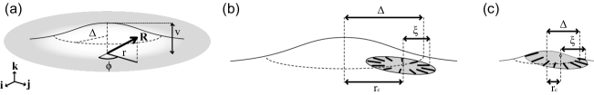
A Gaussian bump is one of the exemplary curved surfaces for studying the correlation mentioned above. It has a continuous rotation symmetry around a vertical axis, showing a positive (negative) Gaussian curvature close to (far from) the top of the bump [see Fig. 1(a)]. The coexistence of a positively curved region and a negatively one on the same surface allows a simultaneous observation of the curvature effects at the two distinct regions with oppositely-signed Gaussian curvature. Earlier work suggested that when a nematic liquid crystal film is placed on a Gaussian bump, a point disclination with charge is trapped to the top of the bump due to the curvature potential [32, 33]. Contrariwise, we have found in the previous work that point disclinations are attracted to the inflection point of the bump regardless of their charges [38]. These two results appear controversial; a possible clue to resolve the controversy is the difference in the assumed bump widths between the two existing studies. In the former study, the bump width is sufficiently small, so that the bump is covered almost entirely by a single disclination as depicted in Fig. 1(c). This situation is expressed by saying that the coherence length [39, 40], , of the nematic order fluctuation exceeds the scale of the bump width (see §2 for the definition of ). In contrast, the latter study was based on the assumption that the bump width is larger enough than the coherence length and the system can involve many small disclinations [see Fig. 1(b)]. It is thus reasonable to conjecture that the ratio of the bump width to the coherence length plays a decisive role in determining the stable position of disclinations on a Gaussian bump. Furthermore, the two contrasting results imply the existence of a threshold ratio across which the stable position of disclinations alters.
In the present Letter, we prove our conjecture by showing a sudden shift in the stable position of a disclination with increasing the bump width. Once the bump width exceeds a threshold value, the stable position is suddenly switched from the top to the inflection point of the bump. The positional shift is described by a power law function of the bump width, as is analogous to the second-order phase transitions of various physical systems whose properties are characterized by power-law behaviors. The present result thus indicates a novel kind of phase transition that is peculiar to curved nematic films.
2 Method
We consider point disclinations in a nematic liquid crystal membrane having a Gaussian bump geometry. The bump is described by a position vector , where , , are right-handed orthogonal basis vectors [see Fig. 1(a)]. The constant , which we call the bump width, determines the inflection point of the bump at which . A dimensionless parameter quantifies the convexity of the bump; for the flat plane, and for a spiky bump. We fix throughout the paper, as a result of which spatial variation of the surface curvature is smooth and sufficiently slight to be accessible in experiments.
Our aim is to evaluate the stable position of a disclination constrained on the Gaussian bump. It is solved by calculating the elastic free energy of the director field around the disclination core, since takes a minimum at the stable position to be evaluated. We assign the core of a disclination at with arbitrary , and assume that the disclination is endowed with the coherence length of the nematic order fluctuation. The latter assumption ensures a radial pattern of within a circular region having the radius centered at the core [i.e., the hatched regions depicted in Figs. 1(b) and 1(c)] 222Precisely speaking, the area slightly deviates from an exact circle due to the finite curvature of the surface. In fact, we define the perimeter of by the locus of points whose distances from the core are equal to in the sense of geodesic distance. Therefore, the perimeter is distorted a bit from the exact circle.. The radial pattern of is gradually distorted with increasing distance from the core; in fact, two-point correlation in the director orientation disappears if the points are well separated by a distance larger than . A typical value of is on the order of tens micrometers as can be estimated from polarization microscope images of liquid crystal films [41, 42].
The continuum elastic theory states that associated with the disclination reads as [43, 44]
| (1) |
where is a vector operator whose components are the covariant derivative [45] on the curved surface. The constant is the thickness of the liquid crystal film; , and are the elastic constants associated with splay, bend and saddle-splay distortions of the field , respectively [46]. The integration range in Eq. (1) is restricted to the finite circular region , despite of slow decay in the elastic energy density with distance from the core; we will revisit this issue in §4. To avoid the divergence in at the core, we introduce an inner cut-off around the core according to the formula , in which is the nematic-isotropic transition temperature and is the temperature of the system [47].
In actual calculations, we set and by referring to the experimental observation [40, 48]. The values of and are those of 4-methoxybenzylidene-4′-butylaniline (MBBA): pN, pN at room temperature [46]. Since the corresponding value of was not yet measured, we set pN on the basis of the relation that involves the twist coefficient pN for MBBA [49].
3 Results
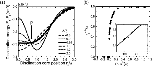
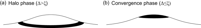
Figure 2(a) shows the disclination energy as a function of the core position . The normalized bump width, , ranges from to . For , the curve of is convex downward, showing a minimum at . The energy scale of the potential depth corresponds to at a temperature of , which is by far larger than the thermal excitation energy at room temperature. Hence, this downward peak implies that a disclination is trapped to the annulus region having the radius of surrounding the bump top [see Fig. 3(a)]. We call this annular distribution of disclinations by the “halo” phase, according to the discussion in Ref. [38].
What deserves attention is the -driven transition of the downward peak profile. It follows from Fig. 2(a) that both the position and magnitude of the peak are insensitive to the decrease in until it reaches a specific value of . A drastic change takes place at ; the downward peak in is replaced by a plateau that extends from to . This plateau means that the disclination can move freely within a finite circular region centered at the bump top. It is also found that a further decrease in gives rise to a new downward peak in at . That is, when the bump width is comparable to (or smaller than) the coherence length , then the disclination is trapped at the bump top [see Fig. 3(b)]; this result is in complete agreement with the earlier observation [32, 33]. We call this defect configuration by the “convergence” phase.
We have seen that the peak of appearing at is gradually shifted from the inflection point to the top () of the bump with increasing . Figure 2(b) shows the -dependence of the normalized peak position . For a large bump width (), takes the minimum at implying the halo phase. The disclination halo shrinks with decreasing , and finally it converges at the bump top when . These results indicate the continuous phase transition (i.e., of the second order) of the stable disclination configuration on the Gaussian bump; the system undergoes the transition from the halo phase to the convergence phase across the threshold . This is the main finding of the present Letter.
It is interesting to note that the -dependence of in the halo phase is described by a power law of the form
| (2) |
The inset of Fig. 2(b) evidences the power-law behavior of Eq. (2) with the exponent , which holds over the two orders of the lateral axis. We thus believe that the present result is a precursor of an untouched configurational phase transition peculiar to curved liquid crystal systems, though further studies are needed to establish its universality and physical interpretation.
4 Discussions
The transition of the stable defect configuration we have demonstrated is a consequence of the following two variations caused by reducing : a slight -increase to the right of the arrow marked in Fig. 2(a), and a rapid -decrease to the left of . In this section, we give an outline of the physical mechanisms of the two variations, while a detailed formulation that describes them will be given elsewhere.
The rapid decrease in to the left of originates from a suppression of the splay deformation of the director field around the bump top. Suppose that a disclination is placed near the top of a broad bump as depicted in Fig. 1(c). Since and are constants, a reduction in leads to a lowering of the bump hight remaining the disclination area be fixed. As a result, the disclination is allowed to cover the whole bump. In the latter situation, adjacent directors (thick line segments in the plots) distributed close to the outer edge of tend to be parallel to each other. Eventually, the first integrated term in Eq. (1), , which represents the contribution from the splay deformation of , is suppressed by reducing . This is the reason why at drops off when decreases.
A parallel argument to the above accounts for the slight increase in to the right of in Fig. 2(a). Suppose a disclination on the skirt (i.e., at ) of the bump. If the disclination area intersects the circle around the bump top, then it covers a positively-curved region () and a negatively-curved one (). At the negatively curved region, a reduction in yields an enhancement of the splay deformation which leads to the slight increase in at . A mathematical proof of the splay enhancement has been given in Ref. [38].
The data shown in Figs. 2(a) and 2(b) are derived from a specific Gaussian bump shape characterized by the parameter (see Fig. 1(a)). We also confirmed that, when , the system exhibits the same configurational transition across . A slight increase in with was observed within the range of , reflecting further splay suppressions and enhancements in disclinations whose cores locate at and , respectively. In contrast, the value of is insensitive to the change in .
It should be stated that our discussion is based on the model given by Eq. (1), in which contributions from the outer region than the circle are ignored. In actual nematic layers, a disclination has a profile of the elastic energy density that decays logarithmically with distance from the core. Hence, contributions far from the core may be relevant to the stable position of the disclination, thus should be taken in account in order to obtain a quantitatively accurate value of . The geometric potential approach developed in Ref. [50] will be a clue to solve this issue.
Before closing the Letter, we suggest the following system could allow experimental tests of our theoretical predictions; it is a thin liquid crystal film coating a randomly corrugated substrate. The film involves many disclinations and bumps with various sizes; therefore, we will observe simultaneously the two effects, halo and convergence patterns depicted in Fig. 3, by tuning the surface corrugation. We also mention that such the corrugated substrate can be synthesized by polymer adhesion with patterned surfaces as demonstrated in Ref. [51].
5 Conclusion
We have found a continuous transition of defect configurations in nematic films confined on a Gaussian bump. Depending on the ratio , the system exhibits either of two defect distribution patterns: the halo phase () and convergence phase (). The stable position of defects turned out to obey the power law with the exponent under the present condition. Our findings suggest the possibility of defect manipulation via artificial deformation of liquid crystal films.
Acknowledgments
We would like to thank K. Yakubo, H. Orihara, J. Fukuda and Y. H. Na for fruitful discussions. IH is thankful for the financial support from the Japan Society for the Promotion of Science for Young scientists. HS acknowledges M. Arroyo for his hospitality during the stay in UPC. This work is supported by the Kazima foundation and a Grant-in-Aid for Scientific Research from the Japan Ministry of Education, Science, Sports and Culture.
References
- [1] D. W. Berreman, Phys. Rev. Lett. 28 (1972) 1683.
- [2] J. S. Gwag, J. Fukuda, M. Yoneya and H. Yokoyama, Appl. Phys. Lett. 91 (2007) 073504.
- [3] J. Fukuda, J. S. Gwag, M. Yoneya and H. Yokoyama, Phys. Rev. E77 (2008) 011702.
- [4] G. Barbero, G. Kaniadakis, E. Miraldi and M. L. Rastello, Mod. Phys. Lett. B6 (1992) 1871.
- [5] G. Barbero, A. N. Chuvyrov, G. Kaniadakis, E. Miraldi and M. L. Rastello, J. Phys. II France 3 (1993) 165.
- [6] A. Nesrullajev and F. Z. Tepehan, Int. J. Mod. Phys. B19 (2005) 2975.
- [7] K. Ichimura, Chem. Rev. 100 (2000) 1847.
- [8] J.-Y. Hwang and D.-S. Seo, Jpn. J. Appl. Phys. 40 (2001) 4160.
- [9] J. Y. L. Ho, V. G. Chigrinov and H. S. Kwok, Appl. Phys. Lett. 90 (2007) 243506.
- [10] N. Kawatsuki, A Hiraiwa, K. Tada, M. Kondo, and H. Ono, Jpn. J. Appl. Phys. 48 (2009) 120208.
- [11] C. Chiccoli, P. Pasini, F. Semeria and C. Zannoni, Phys. Lett. A150 (1990) 311.
- [12] E. Berggren, C. Zannoni, C. Chiccoli, P. Pasini and F. Semeria, Phys.Rev. E50 (1994) 2929.
- [13] C. Chiccoli, O. D. Lavrentovich, P. Pasini and C. Zannoni, Phys. Rev. Lett. 79 (1997) 4401.
- [14] D. R. Nelson, Nano Lett. 2 (2002) 1125.
- [15] V. Vitelli and D. R. Nelson, Phys. Rev. E74 (2006) 021711.
- [16] C. D. Santangelo, V. Vitelli, R. D. Kamien, and D. R. Nelson, Phys. Rev. Lett. 99 (2007) 017801.
- [17] A. Fernandez-Nieves, V. Vitelli, A. S. Utada, D. R. Link, M. Márquez, D. R. Nelson, and D. A. Weitz, Phys. Rev. Lett. 99 (2007) 157801.
- [18] H. Shin, M. J. Bowick, and X. Xing, Phys. Rev. Lett. 101 (2008) 037802.
- [19] X. Xing, Phys. Rev. Lett. 101 (2008) 147801.
- [20] T. Lopez-Leon and A. Fernandez-Nieves, Phys. Rev. E79 (2009) 021707.
- [21] L. Z. Ruan, J. R. Sambles and I. W. Stewart, Phys. Rev. Lett. 91 (2003) 033901.
- [22] I. Muševič, M. Škarabot, U. Tkalec, M. Ravnik and S. Žumer, Science 313 (2006) 954.
- [23] D. K. Yoon, M. C. Choi, Y. H. Kim, M. W. Kim, O. D. Lavrentovich and H.-T. Jung, Nat. Mater. 6 (2007) 866.
- [24] G. Skačej and C. Zannoni, Phys. Rev. Lett. 100 (2008) 197802.
- [25] W. Guo, S. Herminghaus and C. Bahr, Langmuir 24 (2008) 8174.
- [26] J. Fukuda, J. Phys. Soc. Jpn. 78 (2009) 041003.
- [27] M. Ravnik and S. Žumer, Soft Matter 5 (2009) 4520.
- [28] M. A. Bates, G. Skačej and C. Zannoni, Soft Matter 6 (2010) 655.
- [29] D. R. Nelson and L. Peliti, J. Phys. France 48 (1987) 1085.
- [30] H. S. Seung and D. R. Nelson, Phys. Rev. A38 (1988) 1005.
- [31] J. -M. Park and T. C. Lubensky, J. Phys. I France 6 (1996) 493.
- [32] V. Vitelli and A. M. Turner, Phys. Rev. Lett. 93 (2004) 215301.
- [33] V. Vitelli and D. R. Nelson, Phys. Rev. E70 (2004) 051105.
- [34] L. R. Gómez and D. A. Vega, Phys. Rev. E79 (2009) 031701.
- [35] H. Shima, H. Yoshioka and J. Onoe, Phys. Rev. B79 (2009) 201401(R).
- [36] S. Ono and H. Shima, Phys. Rev. B79 (2009) 235407.
- [37] S. K. Baek, H. Shima and B. J. Kim, Phys. Rev. E79 (2009) 060106(R).
- [38] I. Hasegawa and H. Shima, J. Phys. Soc. Jpn. 79 (2010) 074607.
- [39] M. Kleman and G. Ryschenkow, J. Chem. Phys. 64 (1976) 413.
- [40] K. Y. Wong and A. F. Garito, Phys. Rev. A34 (1986) 5051.
- [41] J. Nehring and A. Saupe, J. Chem. Soc. Faraday Trans. 2 68 (1972) 1.
- [42] T. Shiwaku, A. Nakai, H. Hasegawa and T. Hashimoto, Macromolecules 23 (1990) 1590.
- [43] C. D. Santangelo and R. D. Kamien, Proc. R. Soc. A461 (2005) 2911.
- [44] M. Kleman and O. D. Lavrentovich, Philos. Mag. 86 (2006) 4117.
- [45] H. Shima and T. Nakayama, Higher Mathematics for Physics and Engineering (Springer-Verlag, Berlin, 2010).
- [46] I. W. Stewart, The Static and Dynamic Continuum Theory of Liquid Crystals (Taylor & Francis, London and New York, 2004).
- [47] P. E. Cladis and M. Kleman, J. Phys. France 33 (1972) 591.
- [48] R. R. Shah and N. L. Abbott, J. Phys. Chem. B105 (2001) 4936.
- [49] J. Nehring and A. Saupe, J. Chem. Phys. 56 (1972) 5527.
- [50] V. Vitelli, J. B. Lucks and D. R. Nelson, Proc. Natl. Acad. Sci. U.S.A. 103 (2006) 12323.
- [51] E. P. Chan, D. Ahn and A.J. Crosby, J. Adhesion 83 (2007) 473.