Effect of heat treatment on mechanical dissipation in Ta2O5 coatings
Abstract
Thermal noise arising from mechanical dissipation in dielectric reflective coatings is expected to critically limit the sensitivity of precision measurement systems such as high-resolution optical spectroscopy, optical frequency standards and future generations of interferometric gravitational wave detectors. We present measurements of the effect of post-deposition heat treatment on the temperature dependence of the mechanical dissipation in ion-beam sputtered tantalum pentoxide between 11 K and 300 K. We find the temperature dependence of the dissipation is strongly dependent on the temperature at which the heat treatment was carried out, and we have identified three dissipation peaks occurring at different heat treatment temperatures. At temperatures below 200 K, the magnitude of the loss was found to increase with higher heat treatment temperatures, indicating that heat treatment is a significant factor in determining the level of coating thermal noise.
pacs:
05.40.Jc, 61.43.Er, 68.60.Bs, 04.80.Nn, 95.55.Ym, 42.60.Da1 Introduction
Several long baseline gravitational wave detectors have been constructed and used in searches for gravitational radiation from astrophysical sources [1, 2, 3, 4]. These detectors use interferometric sensing to search for displacements, induced by gravitational waves, of test masses which are suspended as pendulums at the ends of perpendicular arms up to 4 km in length. The test masses are coated to form mirrors which are highly reflective at 1064 nm. The thermal displacement noise associated with the test mass mirrors is a significant limit to the sensitivity of these detectors [5, 6, 7]. The magnitude of the thermal noise is directly related to the mechanical dissipation of the materials used to construct the mirrors. In particular, the mechanical dissipation of the amorphous dielectric mirror coatings has been identified as an important noise source which is likely to limit the sensitivity of the generation of detectors currently being constructed, such as Advanced LIGO [8] and Advanced Virgo [9], in their most sensitive frequency band [10, 11, 12, 13]. Coating thermal noise is also expected to significantly limit the performance of highly frequency-stabilized lasers for use in high resolution optical spectroscopy [14], optical frequency standards [15, 16] and fundamental quantum measurements [17].
The mirror coatings used in current gravitational wave detectors are formed from alternating layers of silica (SiO2) and tantalum pentoxide (Ta2O5) deposited by ion-beam sputtering. Research has shown that the mechanical dissipation of these multi-layer coatings is dominated by the dissipation of the Ta2O5 layers [18, 19, 20] and that the total dissipation of a multi-layer coating can be reduced by up to 40 by doping the Ta2O5 with titania (TiO2) [21]. However, neither the process responsible for mechanical dissipation in Ta2O5 nor the mechanism by which TiO2 doping reduces the dissipation is as yet understood.
In a recent paper we reported data showing a low temperature dissipation peak in a Ta2O5 coating doped with TiO2 and heat treated at 600 ∘C [22]. There is evidence that this peak arises from a thermally activated dissipation mechanism, possibly related to the reorientation of Ta-O bonds within a double well potential, similar to the mechanism believed to occur in fused silica [23, 24, 25]. Further work has suggested that the effect of the TiO2 doping is to increase the activation energy of the dissipation process [26], thereby reducing the mechanical loss of the material. A barrier height distribution function analysis revealed that the effect of TiO2 doping was to shift the distribution of potential barriers to a higher energy and to broaden the peak in the distribution. Heat treatment is another possible method of altering the distribution of potential barrier heights. Ion-beam sputtered coatings are often heat treated after deposition to reduce the stress in the film and to reduce the optical absorption [27]. Several studies have shown that post-deposition heat treatment of ion-beam sputtered amorphous oxide layers can increase the thickness of the film, with a corresponding reduction in density [27, 28, 29, 30]. Furthermore it is known heat treatment can significantly reduce the mechanical loss of bulk fused silica [31]. This is believed to be a result of a reduction of internal stresses in the silica, possibly altering the distribution of the potential barrier heights [32]. Thus investigating the effects of heat treatment on the mechanical loss of Ta2O5 is of particular interest for understanding, and perhaps reducing, the mechanical dissipation. In addition to providing insights into the mechanisms of energy dissipation in Ta2O5, measurements of the temperature dependence of the coating dissipation are critical for the design of future gravitational wave detectors such as ET [33] and LCGT [34] which may use cryogenic cooling to reduce thermal noise.
2 Sample preparation and experimental technique
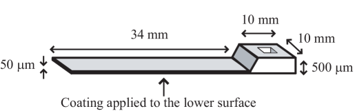
The Ta2O5 coatings were deposited onto rectangular silicon cantilever substrates. These substrates consist of a 0.5-mm-thick clamping block and a thinner flexing portion of length 34-mm and thickness 50 m, as shown in Figure 1. The sample geometry was designed to reduce frictional energy losses into the clamp used to support the cantilever during mechanical loss measurements [35, 36]. A thermal oxide layer of approximately 30 nm thickness was grown on the cantilevers prior to coating to ensure proper adhesion of the Ta2O5. A Ta2O5 film (0.49 0.1) m in thickness was deposited on one face of the flexing part of each cantilever by ion-beam sputtering using argon as the sputtering ion. Four fused silica disks, 25.4 mm in diameter, were coated in the same coating run to serve as witness samples for microscopic analysis of the coating structure. A coated cantilever, a nominally identical uncoated cantilever and a coated silica disk were heat treated in air at each of the following temperatures: 300, 400, 600 and 800 ∘C. The samples were heated to the desired temperature at 2 ∘C per minute and held at this temperature for 24 hours after which they were allowed to cool naturally. The coating and heat treatment process was carried out by CSIRO222Industrial Physics Division, Commonwealth Scientifc and Industrial Research Organisation, West Lindfield, NSW, Australia.
Ion-beam sputtered Ta2O5 films have been observed to crystallize when heated to approximately 600 to 700 ∘C [37], to the detriment of their optical properties. The highest heat treatment temperature of 800 ∘C was chosen to allow study of the mechanical loss on either side of this transition region.
The mechanical dissipation factors of several resonant modes of each coated cantilever and the associated uncoated control cantilever were measured between 11 and 300 K in a cryostat using a ring-down technique, in which a resonant mode of the sample of angular frequency was excited to an amplitude and the vibration allowed to decay freely. The time dependence of the amplitude ring-down is given by:
| (1) |
where is the mechanical dissipation factor. The cantilever was mounted in a stainless steel clamp within the vacuum chamber of the cryostat and the bending modes excited by an electrostatic actuator located a few mm below the cantilever. The frequency of the n bending mode can be calculated as follows [38]:
| (2) |
where is the density, the Young’s modulus, the thickness and the length of the cantilever. is a numerical factor which takes the values 1.875, 4.694, 7.855 and 10.996 for = 1 to 4 respectively. For , can be approximated as . The vibration amplitude was measured by means of a laser beam reflected from the cantilever surface and directed onto a photodiode sensor outside the cryostat. The sensor consisted of a rectangular photodiode masked so that a thin triangular strip of the surface was exposed. Vibrations of the cantilever resulted in motion of the reflected laser beam along the triangular sensor, producing a signal proportional to the vibration amplitude. This sensor arrangement was found to be more practical than a quadrant photodiode due to the large amplitude of motion of the laser spot.
Several measurement cycles, in each of which the sample temperature was increased incrementally from 11 to 300 K, were carried out. Repeated ring-down measurements at each temperature generally showed a variation in loss factor of less than 5 for each mode. The variation in the loss factor between the various temperature cycles was typically less than 10. The temperature of the cantilever was measured using a silicon-diode sensor (Lakeshore DT-670 A) mounted within the clamp immediately below the fixed end of the cantilever.
3 Results
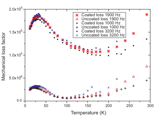
Figure 2 shows, as an example, the loss factors measured for the coated and uncoated cantilevers heat treated at 300 ∘C. The increase in loss due to the presence of the Ta2O5 film can be clearly observed throughout the temperature range studied. Of particular note is the peak in the loss of the coated cantilever at approximately 35 K - this will be discussed in more detail in the following section. The dissipation of the uncoated cantilever also exhibits a peak at between 25 to 30 K. A similar peak was observed for all of the uncoated samples studied. Peaks have been observed at similar temperatures in silica films grown on silicon by wet thermal oxidation [39], and it seems likely therefore that these peaks are due to the thermal oxide layer grown on all of the cantilevers.
The mechanical loss of the Ta2O5 film was calculated from the difference in the loss factors of the coated and uncoated cantilevers using the following equation [40]:
| (3) |
where is the angular frequency of the mode, is the loss factor of the coated cantilever, is the loss factor of the cantilever prior to coating, and are the thickness and Young’s modulus of the substrate respectively and and are respectively the thickness and Young’s modulus of the coating. The Young’s moduli of silicon and Ta2O5 were taken to be 166 GPa [41] and (140 15) GPa [42] respectively. Assuming that the temperature dependence of the Young’s modulus of Ta2O5 is typical of other amorphous oxides [43], then its effect on the calculation over the temperature range studied here is negligible.
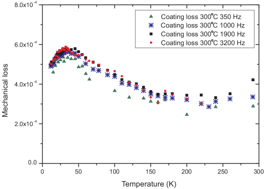
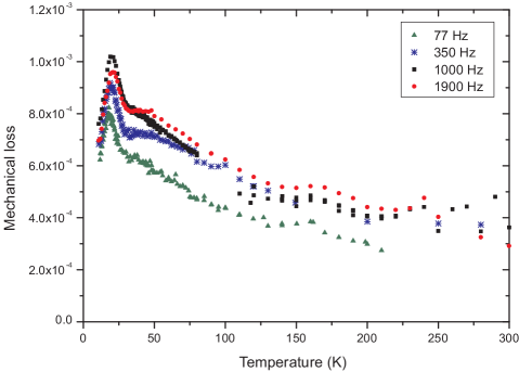
Figure 3 shows the calculated mechanical dissipation of the Ta2O5 film heat treated at 300 ∘C, obtained from the data in Figure 2 using Equation 3. The same procedure was followed to find the loss of the coatings which had been heat treated at 400, 600 and 800∘C. Data was obtained at several mode frequencies for each sample, and Figures 4 to 6 show comparisons of the loss of the series of coatings at 1000 Hz, 1900 Hz, 3000 Hz and 350 Hz respectively.
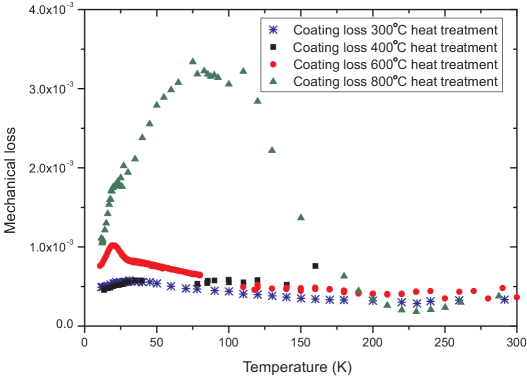

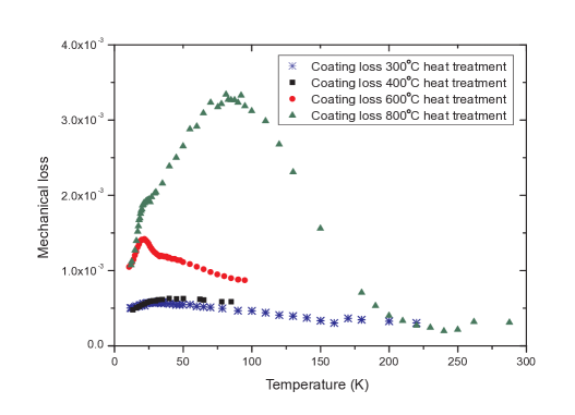
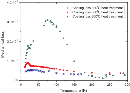
The results clearly show that the temperature of the post-deposition heat treatment had a significant effect on the temperature dependence of the mechanical loss factor of the Ta2O5 coatings. There are several notable features in the data. Firstly, a broad peak in the dissipation of the Ta2O5 film heat treated at 300 ∘C was observed at approximately 35 K. The data for the coated cantilever which was heat treated at 400 ∘C is incomplete as the cantilever cracked in the clamp during a measurement cycle. The breakage was indicated by a sudden change in the resonant frequencies of the cantilever and an increase in the measured mechanical dissipation factors. However, below 100 K the loss of this coating follows a similar trend to the coating heat treated at 300 ∘C, with a broad dissipation peak at 35 K.
Secondly, a sharper additional peak in the dissipation of the Ta2O5 film heat treated at 600 ∘C was observed at approximately 20 K. This is in qualitative agreement with previous measurements of Ta2O5 films supplied by LMA333Laboratoire des Matériaux Avancés, LMA, CNRS-IN2P3, France, http://lma.in2p3.fr. and heat treated at the same temperature [22, 26]. This peak at 20 K is significantly narrower and higher than the peak at 35 K observed in the coatings heat treated at 300 and 400 ∘C. At temperatures above 40 K, the dissipation of the coating heat treated at 600 ∘C shows a similar trend in shape to that for the 300 and 400 ∘C coatings, although the absolute level of dissipation is somewhat higher below 250 K. This suggests that the 35 K peak may also be present in the film heat-treated at 600 ∘C, partially underlying the tail of the 20 K peak.
Thirdly, the Ta2O5 coating treated at 800 ∘C exhibits a large and very broad dissipation peak at 80 to 90 K. A small plateau in the low temperature edge of this peak is apparent at each measurement frequency, suggesting that the 20 K dissipation peak is also present. At temperatures between 200 and 250 K, this coating has a lower dissipation than those heat treated at lower temperatures, with the minimum dissipation occurring at approximately 225 K. The increase in the dissipation between 225 K and 300 K may be indicative of an additional dissipation peak occurring above room temperature. However, further investigation was beyond the scope of the current study, as the sensitivity with which the loss factor of the coating can be measured is significantly reduced at room temperature and above due to the relatively high dissipation factor of the silicon cantilever substrates at these temperatures.
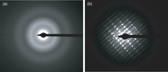
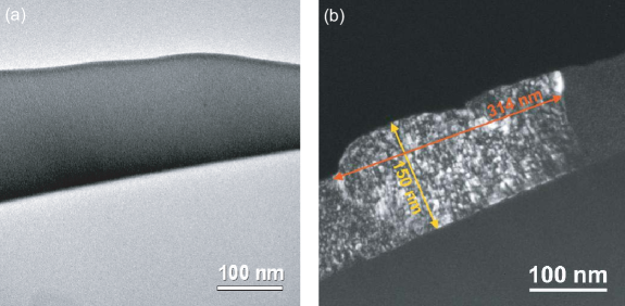
As noted above, ion-beam sputtered Ta2O5 has been observed to crystallize at temperatures between 600 and 700 ∘C. The structure of the Ta2O5 films was investigated by electron diffraction measurements of the the witness samples which were coated and heat treated at the same time as the cantilevers. The results, shown in Figure 8, indicate that the coatings heat treated at 600 ∘C and below are amorphous, while the coating heat treated at 800 ∘C has a crystalline structure. The difference in structure is also apparent from comparison of transmission electron microscope (TEM) images of the coatings heat treated at 600 and 800 ∘C, as shown in Figure 9. It is likely therefore that the large dissipation peak centered on 80 to 90 K is associated with the poly-crystalline structure of the Ta2O5 induced by the heat treatment at 800 ∘C. One possible dissipation mechanism in poly-crystalline materials is phonon scattering at the grain boundaries [44].
4 Analysis
For both the dissipation peak near 20 K and the peak near 35 K, the temperature at which the peak occurred was found to vary with frequency. This behaviour, which can be seen clearly in Figure 10 for the coating heat treated at 600 ∘C, is a typical characteristic of a thermally activated dissipation process. These processes can be characterized by a rate constant, , and an activation energy, , which are related by the Arrhenius equation [44]:
| (4) |
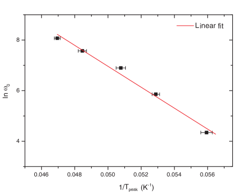
where is the relaxation time associated with the dissipative system returning to equilibrium after a perturbation. Analysis of these dissipation processes shows that the temperature of the dissipation peak, , at angular frequency is related to the activation energy and rate constant as follows [44]:
| (5) |
Thus a plot of against should yield a straight line, from which the activation energy and rate constant for the dissipation process can be obtained. Figure 11 shows this analysis for the peak near 20 K in the coating heat treated at 600 ∘C. The activation energy and rate constant, calculated from the linear fit, were found to be (35.6 2.5) meV and (9.9 0.5) s respectively. The activation energy is somewhat higher than a previous measurement of (28.6 1.6) meV for Ta2O5 deposited by LMA. The difference in activation energy could arise from differences in the detailed structure of the amorphous coating induced by variations in the ion-beam sputtering deposition process between coating vendors.
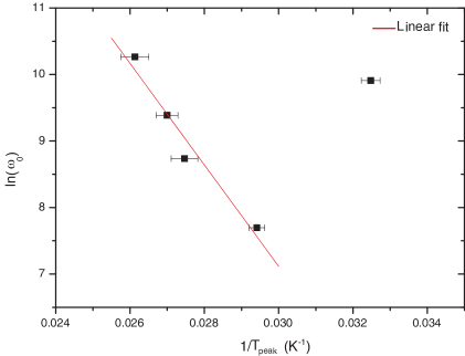
The Arrhenius plot for the peak near 35 K observed for the coating heat treated at 300 ∘C is shown in Figure 12. A straight line could be fitted to the data for four of the modes studied. However, the point on the Arrhenius plot corresponding to the mode at 3200 Hz clearly does not follow this linear trend. It is possible that a torsional mode close in frequency to the 5 bending mode was measured unintentionally, which may explain the difference in the loss peak for this mode. If this point is neglected the fit for the remaining modes gives an activation energy of (66 10) meV and a rate constant of (9.4 0.9) s.
In many amorphous solids, the dissipation at temperatures above 10 K is thought to result from thermally activated reorientations of bonds over potential barriers of height [45]. If the dissipation is modelled as arising from transitions in an asymmetric double-well potential in some local configuration coordinate, it can be shown that the measured mechanical loss is related to the distribution of energy barrier heights by the following expression [46]:
| (6) |
where
| (7) |
and is the appropriate elastic constant for the mode-shape under consideration, is the elastic coupling constant which represents the coupling between the defect (e.g. a bond re-orienting within the double well potential) and the applied strain and is a constant representing the asymmetry between the depth of the two potential wells in each double-well system. The relaxation time associated with a barrier height is given by Equation 4. The assumptions made in this model are discussed in detail by Topp and Cahill [46].
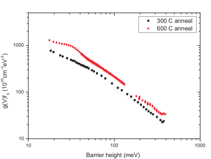
Thus the measured mechanical loss can be used to extract the distribution of barrier heights (i.e. activation energies) for the loss mechanism associated with a particular dissipation peak. The extracted barrier height distributions for the Ta2O5 heat treated at 300 ∘C and 600 ∘C are shown in Figure 13. At all barrier energies, the magnitude of the function is larger for the coating heat treated at 600 ∘C. An interpretation of this is that there are more barriers contributing to the dissipation in this coating, resulting in a higher mechanical dissipation. The feature in the distribution function at a barrier height energy of 35 meV corresponds to the average activation energy calculated from the Arrhenius plot. This feature appears to be superimposed on a background distribution similar to that found for the coating heat treated at 300 ∘C.
The shape of the barrier height distribution for the 35 K loss peak in the coating heat treated at 300 ∘C is broadly similar to the distribution found in bulk fused silica [46], with decreasing smoothly with increasing barrier energy. We postulate that the dissipation mechanisms in Ta2O5 may be similar to that in fused silica and other amorphous solids, and be related to the reorientation of oxygen atoms, or groups of tantalum and oxygen atoms, in a double-well potential. Several models of the dissipation mechanism in fused silica have been proposed, including motion of Si-O bonds between stable angles [47], elongation of Si-O bonds [25], rotation of SiO4 tetrahedral structures [48, 49] or of groups of these structures [50]. If similar processes are responsible for the loss in Ta2O5, it is possible that the peaks observed at 20 K and 35 K correspond to two different types of motion, one of which is only activated by changes in the local ordering induced by heat treatment at temperatures close the the crystallization temperature. Further detailed studies of the short range structure in Ta2O5 coatings using electron diffraction data and computer modelling are ongoing [51].
5 Conclusions
The temperature dependence of the mechanical dissipation in Ta2O5 films has been found to be strongly dependent on the temperature at which post-deposition heat treatment is carried out. We have identified three dissipation peaks arising from dissipation mechanisms which occur after heat treatment at different temperatures. The previously observed dissipation peak at 20 K has been shown to arise from heat treatment close to the temperature at which the amorphous Ta2O5 crystallizes. The dissipation mechanism responsible for this peak may therefore be related to pre-crystallization changes in the local ordering of the Ta2O5 film. A dissipation peak at approximately 35 K was observed in Ta2O5 films heat-treated at 300 and 400 ∘C. There is evidence that this peak is also present in Ta2O5 heat treated at 600 ∘C, underlying the larger dissipation peak at 20 K. We postulate that the two low temperature dissipation peaks may arise from two different types of thermally activated transitions. The Ta2O5 film heat-treated at 800∘C, which was found to have crystallized, had a very broad dissipation peak centered on 90 - 100 K.
Below 200 K the dissipation of the Ta2O5 coatings was found to increase at higher heat treatment temperatures, suggesting that minimizing the temperature at which post-deposition heat treatment is carried out may allow a significant decrease in the coating thermal noise in future cryogenic gravitational wave detectors, thus extending their astronomical reach. As heat treatment is also known to affect the optical absorption of dielectric coating, studies of the optical properties of Ta2O5 heat-treated at various temperatures would be of interest.
The dissipation of Ta2O5 coatings at room temperature appears to be related to the broad tail of the dissipation peak at 35 K. However there is some evidence, particularly for the coating heat-treated at 800 ∘C, of an increase in dissipation close to room temperature. Thus further study of the dissipation in Ta2O5 at temperatures above 300 K would be of significant interest to determine if additional dissipation peaks occurring at temperatures greater than 300 K may contribute to the room temperature dissipation.
Further work is underway to investigate the relationship between the short range structure of Ta2O5 films and the mechanical loss. In addition, it would be of significant interest to study the emergence of the various dissipation peaks in Ta2O5 by studying coatings heat treated at more temperature intervals between 400 and 800 ∘C.
References
- [1] A. Abramovici, W. E. Althouse, R. W. P. Drever, Y. Gursel, et al., Science 256 (1992) 325–333.
- [2] H. Lück, M. Hewitson, P. Ajith, B. Allen, et al., Class. Quantum Grav. 23 (2006) S71–S78.
- [3] F. Acernese, P. Amico, M. Alshourbagy, F. Antonucci, et al., Class. Quantum Grav. 24 (2007) S381–S388.
- [4] R. Takahashi, the TAMA Collaboration, Class. Quantum Grav. 21 (2004) S403–S408.
- [5] P. Saulson, Phys. Rev. D 42 (1990) 2437–2445.
- [6] H. B. Callen, R. F. Greene, Phys. Rev. 86 (1952) 702–710.
- [7] H. B. Callen, T. A. Welton, Phys. Rev. 83 (1951) 34–40.
- [8] G. M. Harry, for the LIGO Scientific Collaboration, Class. Quantum Grav. 27 (2010) 084006.
-
[9]
R. Flaminio, A. Freise, A. Gennai, P. Hello, Advanced Virgo White Paper,
Virgo internal document VIR-NOT-1390-304 (2005).
URL http://wwwcascina.virgo.infn.it/advirgo/docs/whitepaper.pdf - [10] Y. Levin, Phys. Rev. D 57 (1998) 659–663.
- [11] N. Nakagawa, A. M. Gretarsson, E. K. Gustafson, M. M. Fejer, Phys. Rev. D 65 (2002) 102001.
- [12] G. Harry, A. Gretarsson, P. Saulson, S. Kittelberger, et al., Class. Quantum Grav. 19 (2002) 897–917.
- [13] D. R. M. Crooks, P. Sneddon, G. Cagnoli, J. Hough, et al., Class. Quantum Grav. 19 (2002) 883–896.
- [14] R. J. Rafac, B. C. Young, J. A. Beall, W. M. Itano, et al., Phys. Rev. Lett. 85 (2000) 2462–2465.
- [15] A. D. Ludlow, M. M. Boyd, T. Zelevinsky, S. M. Foreman, et al., Phys. Rev. Lett. 96 (2006) 033003.
- [16] S. A. Webster, M. Oxborrow, P. Gill, Opt. Lett. 29 (2004) 1497–1499.
- [17] F. Schmidt-Kaler, S. Gulde, M. Riebe, T. Deuschl, et al., Journal of Physics B: Atomic, Molecular and Optical Physics 36 (2003) 623–636.
- [18] S. D. Penn, P. H. Sneddon, H. Armandula, J. C. Betzwieser, et al., Class. Quantum Grav. 20 (2003) 2917–2928.
- [19] D. Crooks, G. Cagnoli, M. Fejer, A. Gretarsson, et al., Class. Quantum Grav. 21 (2004) 1059–1065.
- [20] D. R. M. Crooks, G. Cagnoli, M. M. Fejer, G. Harry, et al., Class. Quantum Grav. 23 (2006) 4953–4965.
- [21] G. M. Harry, M. R. Abernathy, A. E. Becerra-Toledo, H. Armandula, et al., Class. Quantum Grav. 24 (2007) 405–415.
- [22] I. Martin, H. Armandula, C. Comtet, M. M. Fejer, et al., Class. Quantum Grav. 25 (5) (2008) 055005.
- [23] V. B. Braginsky, V. P. Mitrofanov, V. I. Panov, Systems with small dissipation, University of Chicago Press, Chicago, 1985.
- [24] H. E. Bömmel, W. P. Mason, A. W. Warner, Phys. Rev. 102 (1956) 64–71.
- [25] R. E. Strakna, Phys. Rev. 123 (1961) 2020–2026.
- [26] I. Martin, H. Armandula, C. Comtet, M. M. Fejer, et al., Class. Quantum Grav. 26 (2009) 155012.
- [27] R. P. Netterfield, M. Gross, F. N. Baynes, K. L. Green, et al., Proc. SPIE 5870 (2005) 58700H.
- [28] M. Tilsch, V. Scheuer, T. T. Tschudi, Proc. SPIE 3133 (1997) 163–175.
- [29] J. T. Brown, Appl. Opt. 43 (2004) 4506–4511.
- [30] A. J. Waldorf, J. A. Dobrowolski, B. T. Sullivan, L. M. Plante, Appl. Opt. 32 (1993) 5583–5593.
- [31] K. Numata, K. Yamamoto, H. Ishimoto, S. Otsuka, et al., Phys. Lett. A 327 (2004) 263–271.
- [32] B. S. Lunin, Physical and Chemical Bases for the Development of Hemispherical Resonators for Solid-State Gyroscopes, Moscow Aviation Institute, Moscow, 2005.
- [33] M. Punturo, et al., Einstein Gravitational Wave Telescope, proposal to the European Commission, Framework Programme 7, http://www.ego-gw.it/ILIAS-GW/FP7-DS/fp7-DS.htm.
- [34] K. Kuroda, et al., Status of LCGT, Class. Quantum Grav. 27 (2010) 084004.
- [35] T. J. Quinn, C. C. Speake, R. S. Davis, W. Tew, Phys. Lett. A 197 (1995) 197–208.
- [36] K. Y. Yasamura, T. D. Stowe, E. M. Chow, T. Pfafman, et al., J. Microelectromech. Sys. 9 (2000) 117–125.
-
[37]
R. Netterfield, CSIRO Report, Ion Beam Deposited Coatings, LIGO
Document Control Centre No. T040236-00-D (2004).
URL http://www.ligo.caltech.edu/docs/T/T040236-00/ - [38] N. W. McLachlan, Theory of Vibrations, Dover, 1952.
- [39] B. E. White, R. O. Pohl, Phys. Rev. Lett. 75 (1995) 4437–4439.
- [40] B. S. Berry, W. C. Pritchet, IBM J. Res. Dev. 19 (1975) 334–343.
- [41] Y. S. Touloukian, E. H. Buyco, Thermo-physical Properties of Matter, Plenum, New York, 1970.
- [42] P. Martin, et al., in: P. Townsend, T. Weihs, J. Sanchez, P. Borgesen (Eds.), Materials Research Society Symposium Proceedings, Vol. 308, Materials Research Society, 1993, pp. 583–588.
- [43] J. W. Marx, J. M. Sivertsen, Journal of Applied Physics 24 (1952) 81–87.
- [44] A. Nowick, B. Berry, Anelastic Relaxation in Crystalline Solids, Academic Press, New York, 1972.
- [45] K. S. Gilroy, W. A. Phillips, Philos. Mag. B 43 (1981) 735–746.
- [46] K. A. Topp, D. G. Cahill, Z. Phys. B: Condens. Matter 101 (1996) 235–245.
- [47] O. L. Anderson, H. E. Bommel, J. Am. Ceram. Soc. 38 (1955) 125–131.
- [48] M. R. Vukcevich, J. Non-Cryst. Solids 11 (1972) 25–63.
- [49] U. Buchenau, N. Nücker, A. J. Dianoux, Phys. Rev. Lett. 53 (1984) 2316–2319.
- [50] J. Reinisch, A. Heuer, Phys. Rev. Lett. 95 (2005) 155502.
- [51] R. Bassiri, K. B. Borisenko, D. J. H. Cockayne, J. Hough, et al., J. Phys. Conf. Ser. in press.