Spintronic Properties of Zigzag-Edged Triangular Graphene Flakes
Abstract
We investigate quantum transport properties of triangular graphene flakes with zigzag edges by using first principles calculations. Triangular graphene flakes have large magnetic moments which vary with the number of hydrogen atoms terminating its edge atoms and scale with its size. Electronic transmission and current-voltage characteristics of these flakes, when contacted with metallic electrodes, reveal spin valve and remarkable rectification features. The transition from ferromagnetic to antiferromagnetic state under bias voltage can, however, terminate the spin polarizing effects for specific flakes. Geometry and size dependent transport properties of graphene flakes may be crucial for spintronic nanodevice applications.
pacs:
73.63.-b, 72.25.-b, 75.75.+aI INTRODUCTION
Graphene and graphene based nanostructures are focus of intensive research activities due to their impressive material properties novo1 ; novo2 ; zhang ; morozov ; lee ; bolotin and promising application potential ultrafast ; readout ; wang ; kim ; yan ; murali in novel electronic devices. In particular edge-localized spin polarizations found in graphene ribbons edge-states ; cohen , flakes hasan-transport ; ezawa2 ; hod2 , and at defect sites defect1 ; defect2 introduce magnetic properties that can be utilized for spintronic applications. Recent studies have also revealed the ferromagnetic ground state of graphene nanodotshod , triangular shaped graphene fragmentsakola ; kaxiras ; chemphys ; Rozhkov and graphene domains on 2D hydrocarbonshasan-apl and the possibility of observing spin polarized current voltage characteristics of such graphene flakes.
While pristine graphene provides high carrier mobility and ambipolar behavior, semiconductor nanoscale materials having tunable bandgap are more desirable from the perspective of potential nanoelectronics applications. In this context, recent efforts have been devoted to precise controlling electronic and magnetic properties of graphene sheets by functionalization via adatom adsorption. The synthesis of a 2D hydrocarbon in honeycomb structure, namely graphane,elias ; sofo ; boukhvalov ; Graphene to graphane is one of the succesfull example for such functionalization. Very recently, we reported the possibility of obtaining tunable bandgap and magnetization through dehydrogenation of domains on 2D graphane and graphane nanoribbons.hasan-apl ; graphaneNR Stability and electronic properties of graphene flakes uniformly functionalized by methyl (CH3), phenyl (C6H5) and nitrophenyl (C6H4NO2) groups were also discussed earlier.Bekyarova ; Boukhvalov ; Pei
Recent experimental observationsWarner ; girit ; Dresselhaus ; dobrik ; ozyilmaz and theoretical studies gan ; olcay ; wei show that the electronic, magnetic and conductance properties of graphitic fragments can be changed significantly upon the termination of their edges. In addition to purely zigzag and armchair edged graphene, experimental verification of the existence of alternating series of zigzag and armchair segments at the edges and energetics of reconstructions have also been reported.hakinen Originating from the antiferromagnetic ground state of zigzag edges, adatomhasan-transport and topologykuc dependent trends in electronic properties of rectangular flakes have also investigated.
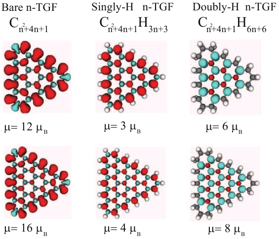
In this work, we study graphene flakes having equilateral triangular shapes with zigzag edges (-TGF), where denotes the number of edge hexagonal cells in one side of the triangle. The flakes have been considered as bare (C), each edge atom being saturated with one (CH3n+3) or two hydrogen atoms (CH6n+6). We find that these flakes have large spin magnetic moment values of , , and , respectively, in units of . When these TGFs have been contacted with thin metallic electrodes we calculate that the current running through them gets both spin-polarized and rectified.
II CALCULATION METHODS
Optimization of geometrical structures of triangular graphene flakes and calculations of their magnetic and electric properties are performed by using the software package Atomistix ToolKit (ATK) atk based on density functional theory (DFT). The spin-dependent exchange-correlation potential is approximated within the generalized gradient approximation. The criteria of convergence used for total energy and Hellman-Feynman forces were eV and 0.005 eV/Å, respectively. The electrostatic potentials were determined on a real-space grid with a mesh cutoff energy of 150 Ry. Double-zeta-polarized basis sets of local numerical orbitals were employed to increase the accuracy of our calculations.
For determination of quantum transport properties of the electrode-TGF-electrode system, ATK use nonequilibrium Green’s function formalism. Transport calculations are performed with the Brillouin zone sampled with (1,1,51) points within the Monkhorst-Pack k-point sampling scheme. The current through the TGFs is determined by summing the transmission probabilities for electron states from one electrode to another within the energy window , where () is the electrochemical potential of the left (right) electrode under the applied bias . Therefore the spin dependent current is given by the formula
| (1) |
where is the quantum conductance unit and is the quantum mechanical transmission probablity for electrons with spin state and energy . During the self-consistent calculation of - spectrum charge on the TGFs is not fixed and energy is minimized with respect to the electrochemical potentials of the electrodes at each voltage increment. In order to achieve convergence of the electronic states with increasing voltages to the desired level of accuracy, calculations performed within the bias window (from -1 to +1 V) in steps of 0.005 V. By using the carbon chains attached to the TGF, it is ensured that the screening occurs in the device region.
III Results
III.1 Atomic and Magnetic Ground State Properties of TGFs
First, we have performed geometry optimizations of TGFs and determined the spin polarized charge density of the optimized structures. Due to the particular shape of the TGFs spin-relaxed calculation leads to lower ground state energies compared to those of spin-unrelaxed calculation; here we have found that ferromagnetically ordered spin accumulation at the edges gives a nonzero magnetic moment to the flake. Apart from minor bond contractions of the edge atoms TGFs preserve their regular hexagonal structure even when the flakes are not hydrogenated. Saturating the edge carbon atoms with either one or two hydrogen atoms considerably modifies the magnetic ground state, by altering the total magnetic moment.
Graphene, with its hexagonal lattice structure resulting from -type hybridization of carbon atoms, is a planar conjugated system. It can be viewed as made up of A- and B-sublattices of carbon atoms. Repulsive case of the Lieb’s theorem lieb reveals uniqueness of the ground state and provides a simple formula for calculating the magnetic ground state of such bipartite systems. According to the rule provided by the theorem, total net spin magnetization of a graphene structure is given by
| (2) |
where for electron, is Bohr magneton, and and denote the number of carbon atoms in A- and B-sublattice, respectively. Each carbon atom in graphene is connected to the nearest neighbors by three covalent bonds, while leaving behind a -orbital electron contributing to the spin magnetic moment. Such electrons in each sublattice have opposite spin states and make spin paired -bonds, thus total spin magnetic moment of the system is zero unless a difference is created in the numbers of atoms of the A- and B-sublattices. In some graphene flakes, such as those having equilateral triangular shapes and zigzag edges, and are different and leads to finite net spin magnetic moments kaxiras ; chemphys . Moreover, in bare (not hydrogenated) flakes the edge carbon atoms that make only two covalent bonds contribute to the spin moment with two nonbonding electrons.
In Fig.1, we present the optimized structures and spin charge density difference () isosurface for bare, singly- and doubly-hydrogenated cases of -TGFs (=4, 5). In general, we see that each carbon atom has an induced spin imbalance opposite to its nearest neighbors, however the spin polarization of hydrogen atoms is negligible.
Calculated total spin magnetic moments of the structures using DFT are in integer multiples of and either verifies the results of Lieb’s theorem or can be understood by simple modifications of it. In the flakes with singly-hydrogenated edges, all the carbon atoms are coordinated as reminiscent of infinite graphene, and in accordance with Lieb’s theorem. When the hydrogen atoms are removed from the flake (bare flake case) the atoms of sublattice A and 3 atoms of sublattice B each have an extra nonbonding electron that contributes to the magnetic moment, consequently giving . On the other hand, in doubly-hydrogenated flakes, all the edge carbon atoms have hybridized electrons with vanishing contribution to spin magnetic moment. Thus, in this case , where the direction of magnetic moment is reversed, and the net moment of the system increases with respect to the singly-hydrogenated case. Tunability of the spin magnetic moments of triangular graphene flakes through degree of hydrogenation is an interesting feature that may be utilized for nanodevice applications. Saturation of TGF edges by other atoms may give rise to similar modifications in their electronic and magnetic structures.
III.2 Transport Properties of TGFs
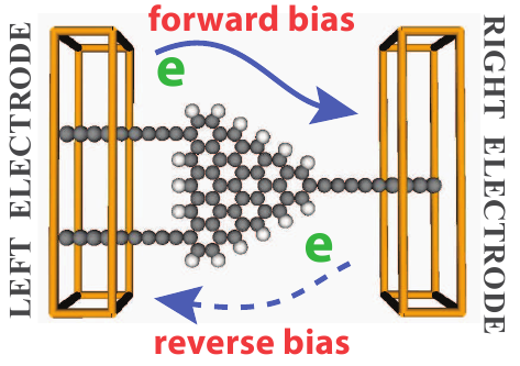
Next we consider electrical conductance and I-V characteristics of TGFs when contacted with metallic electrodes. We use linear carbon chains as model electrodes. Carbon atomic chains which are known to be metallictongay ; hasan-transport are expected to make reasonably good contacts with the flakes. As an alternative to carbon-chain electrodes, earlier the robustness of our conductance calculations was also tested by using semi-infinite gold bar electrodes and consistent results were obtained for rectangular flakes.hasan-transport At the contact sites the introduced hydrogen atoms are removed and connection between electrode and flake carbon atoms is established through double bonds. Due to asymmetric form of device-electrode geometry one expects different current profiles for forward and reverse bias voltages. The convention we have adopted is schematically shown in Fig.2, where forward bias corresponds to flow of electrons from the left to the right electrode, i.e. the current is flowing from right to left electrode.
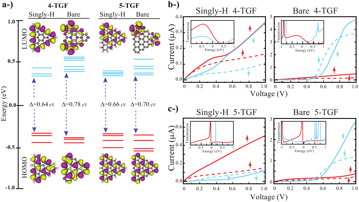
For the ballistic current of electrons, the spin dependent transmission probability from one electrode to other strongly depends on the eigenstates of the TGF molecule. The molecular orbitals perfectly coupled to the electrodes behave as an open channel and provides propagation with minimal scattering through the TGF and hence the magnitude of the transmission coefficient is determined by electrode-device interaction. Eigenstates within the 1 eV energy window, indicating the highest-occupied-molecular-orbital (HOMO) and lowest-unoccupied-molecular-orbital (LUMO) of singly-hydrogenated and bare n-TGFs (n=4,5) are presented in Fig.3 (a). It is obvious that the HOMO-LUMO gap () gets narrower upon the hydrogenation of TGFs. Resulting from the ferromagnetic ground state, within the 1 eV energy window up and down spin states are well-separated around the EF. In the energy window used for Fig.3 (a), all the filled levels are for up-spin states, whereas the unoccupied levels are for down spins. When the TGF molecule is connected to electrodes, however, due to the chain-TGF interactions energy level spectra is changed and it is not easy to exactly distinguish the contribution of TGF and electrode states.
In Fig.3 (b-c), we show the I-V characteristics of 4- and 5-TGFs for bare and singly-hydrogenated cases. Hydrogenated flakes have lower conductance and leads to at least an order of magnitude smaller currents, since the hydrogenation of the flake removes some of the states providing open channels in the flake. While the maximum current in the calculated bias range is 5.00 A for bare TGF, after hydrogenation it is reduced to 0.35 A. Since electrode device coupling broadens the energy levels, and may shift them due to charging, even though there is no molecular state at EF, the tails of HOMO and LUMO states can contribute to the transmission even at small voltages. Orbital character that changes upon the H termination of HOMO and LUMO states reveal the importance of the edge atoms in electron transport. In addition, there is a strong rectification of current for both singly-H and bare edge cases. In this electrode-device configuration forward current gets larger at a threshold bias of 0.6 V. For small voltages, the characteristics of the current flowing through the TGFs can be understood by zero bias transmissions that are given by insets in Fig.3 (b-c). In fact the self consistently calculated voltage dependent transmission spectra provides a better information regarding the I-V characteristics of the device.
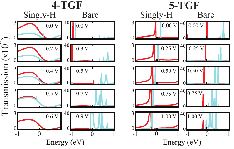
Depending on the applied voltage, triangular graphene flakes display diverse properties. In the case of forward bias application to the singly-hydrogenated 4-TGF, the spin-up current is dominant up to 0.55 V, but after this critical value, the spin-up and spin-down states are merged due to the transition from ferromagnetic to antiferromagnetic state and thus spin polarizing property disappears. This behavior of I-V curves can be revealed from transmission spectrum. Even if the zero bias transmissions shown in insets in Fig.3 (b-c) can explain I-V curves for small bias values, at finite bias voltages the transmission spectrum of the flake changes through broadening and/or shifts of the transmission peaks, which should be calculated self-consistently under nonequilibrium conditions. In Fig.4 we show the variations of transmission spectrum for selected cases under incremental forward bias voltages. For the hydrogenated 4-TGF, while transmission of the up spin channel decreases with increasing voltages, the transmission of down spins is increasing. Eventually both transmission curves are merging at the vicinity of 0.55 V and hence the spin polarization of the current is ceasing. Total magnetic moment of the flake together with electrodes has a bias dependence, gradually decreasing from 2 to zero at the merging point of the up and down spin currents. In contrast, the down spin states of bare 4-TGF under forward bias get closer to the EF and become dominant carriers in the current. This explains how the spin polarization of the current is switched by applied bias. We can also establish a relation between I-V behavior and the corresponding transmission spectrum of bare 5-TGF. Since up and down spin transmission peaks do not show considerable variation within the energy window, the spin polarization of the currents is maintained up to 1 eV.
IV CONCLUDING REMARKS
In summary, we have investigated the electric, magnetic and transport properties of triangle shaped graphene flakes. We have found that in addition to the their ferromagnetic ground state, triangular graphene flakes show spin polarized and rectified current properties depending on edge saturation, flake size, bias voltage and bias direction. Diverse and spin dependent properties of graphene flakes depending on their shape, size and edge saturation keep the promise of variety of application in future nanospintronics.
V ACKNOWLEDGMENTS
This work was supported by TÜBİTAK under Grant No. 106T597, and through TR-Grid e-Infrastructure Project. Computing resources used in this work were partly provided by the National Center for High Performance Computing of Turkey (UYBHM) under Grant No. 2-024-2007.
References
- (1) K. S. Novoselov, A. K. Geim, S. V. Morozov, D. Jiang, Y. Zhang, S. V. Dubonos, I. V. Grigorieva, and A. A. Firsov, Science 306, 666 (2004).
- (2) K. S. Novoselov, A. K. Geim, S. V. Morozov, D. Jiang, M. I. Katsnelson, I. V. Grigorieva, S. V. Dubonos, and A. A. Firsov, Nature 438, 197 (2005).
- (3) Y. Zhang, Y.-W. Tan, H. L. Stormer, and Philip Kim, Nature (London) 438, 201 (2005).
- (4) S. V. Morozov, K. S. Novoselov, M. I. Katsnelson, F. Schedin, D. C. Elias, J. A. Jaszczak, and A. K. Geim, Phys. Rev. Lett. 100, 016602 (2008).
- (5) C. Lee, X. Wei, J. W. Kysar, and J. Hone, Science 321, 385 (2008).
- (6) K. I. Bolotin, F. Ghahari, M. D. Shulman, H. L. Stormer, and P. Kim, Nature (London) 462, 196 (2009).
- (7) F. Xia, T. Mueller, Yu-ming Lin, A. Valdes-Garcia, and P. Avouris, Nature Nanotechnology 4, 839 (2009).
- (8) C. Chen, S. Rosenblatt, K. I. Bolotin, W. Kalb, P. Kim, I. Kymissis, H. L. Stormer, T. F. Heinz, and J. Hone, Nature Nanotechnology 4, 861 (2009).
- (9) X. Wang, L. Zhi, and K. Mullen, Nano Lett. 8, 323 (2008).
- (10) K. S. Kim, Y. Zhao, H. Jang, S. Y. Lee, J. M. Kim, K. S. Kim, J.-H. Ahn, P. Kim, J.-Y. Choi, and B. H. Hong, Nature (London) 457,706 (2009).
- (11) Q. Yan, B. Huang, J. Yu, F. Zheng, J. Zang, J. Wu, B.-L. Gu, F. Liu, and W. Duan, Nano Lett. 7, 1469 (2007).
- (12) R. Murali, K. Brenner, Y. Yang, T. Beck, and J. D. Meindl, IEEE Electron Device Lett., 30,611 (2009).
- (13) H. Lee, Y. Son, N. Park, S. Han, and J. Yu, Phys. Rev. B 72, 174431 (2005).
- (14) Y. Son, M. L. Cohen, and S. G. Louie, Nature (London) 444, 347 (2006).
- (15) H. Şahin and R. T. Senger, Phys. Rev. B 78, 205423 (2008).
- (16) M. Ezawa, Phys. Rev. B 76, 245415 (2007).
- (17) O. Hod, J. E. Peralta, and G. E. Scuseria, Phys. Rev. B 76, 233401 (2007).
- (18) O. V. Yazyev and L. Helm, Phys. Rev. B 75, 125408 (2007).
- (19) J. J. Palacios, J. Fernandez-Rossier, and L. Brey, Phys. Rev. B 77, 195428 (2008).
- (20) O. Hod, V. Barone, and G. E. Scuseria, Phys. Rev. B 77, 035411 (2008).
- (21) J. Akola, H. P. Heiskanen, and M. Manninen, Phys. Rev. B 77, 193410 (2008).
- (22) W. L. Wang, S. Meng, and E. Kaxiras Nano Letters 8, 241 (2008).
- (23) M. R. Philpott, F. Cimpoesu, and Y. Kawazoe, Chem. Phys. 354, 1 (2008).
- (24) A. V. Rozhkov and Franco Nori, Phys. Rev. B 81, 155401 (2010)
- (25) H. Şahin, C. Ataca, and S. Ciraci, Appl. Phys. Lett. 95, 222510 (2009).
- (26) D. C. Elias, R. R. Nair, T. M. G. Mohiuddin, S. V. Morozov, P. Blake, M. P. Halsall, A. C. Ferrari, D. W. Boukhvalov, M. I. Katsnelson, A. K. Geim and K. S. Novoselov, Science 323, 610 (2009).
- (27) J. O. Sofo, A. S. Chaudhari and G. D. Barber, Phys. Rev. B 75, 153401 (2007).
- (28) D. W. Boukhvalov, M. I. Katsnelson and A. I. Lichtenstein, Phys. Rev. B 77, 035427 (2008).
- (29) M. Z. S. Flores, P. A. S. Autreto, S. B. Legoas and D. S. Galvao , Nanotechnology 20, 465704 (2009).
- (30) H. Şahin, C. Ataca, and S. Ciraci, Phys. Rev. B 81, 205417 (2010).
- (31) E Bekyarova, M. E. Itkis, P. Ramesh, C. Berger, M. Sprinkle, W. A. de Heer and R. C. Haddon, J. Am. Chem. Soc. 131 1336 (2009).
- (32) D. W. Boukhvalov and M. I. Katsnelson Phys, Rev. B 78 085413 (2008).
- (33) Qing-Xiang Pei, Yong-Wei Zhang, V. B Shenoy Nanotechnology 21, 115709 (2010)
- (34) J. H. Warner, M. H. Rummeli, Ling Ge, T. Gemming, B. Montanari, N. M. Harrison, B. Buchner, G. Andrew D. Briggs, Nature Nanotechnology 4, 500 (2009).
- (35) J. C.Meyer, C. O. Girit, M. F. Crommie and A. Zettl, Nature 454, 319 (2008).
- (36) X. Jia, M. Hofmann, V. Meunier, B. G. Sumpter, J. Campos-Delgado, José M. Romo-Herrera, H. Son, Ya-Ping Hsieh, A. Reina, J. Kong, M. Terrones, M. S. Dresselhaus, Science 323, 1701 (2009).
- (37) L. Tapaszto, G. Dobrik, P. Lambin, L. P. Biro, Nat. Nanotechnol. 3, 397 (2008).
- (38) M. Y. Han, B. Ozyilmaz, Y. Zhang, P. Kim, Phys. Rev. Lett. 98, 206805 (2007).
- (39) C. K. Gan and D. J. Srolovitz, Phys. Rev. B 81, 125445 (2010)
- (40) O. U. Akturk and M. Tomak, Appl. Phys. Lett. 96, 081914 (2010).
- (41) W. Zhang, L. Sun, Z. Xu, A. V. Krasheninnikov, P. Huai, Z. Zhu and F. Banhart, Phys. Rev. B 81, 125425 (2010).
- (42) P. Koskinen, S. Malola, and H. Häkkinen, Phys. Rev. B 80, 073401 (2009).
- (43) A. Kuc, T. Heine, and G. Seifert, Phys. Rev. B 81, 085430 (2010)
- (44) Distributed by QuantumWise company, Copenhagen, Denmark. http://www.quantumwise.com
- (45) E. H. Lieb, Phys. Rev. Lett. 62, 1201 (1989).
- (46) S. Tongay, R. T. Senger, S. Dag, and S. Ciraci, Phys. Rev. Lett. 93, 136404 (2004).