Elastically driven ferromagnetic resonance in nickel thin films
Abstract
Surface acoustic waves (SAW) in the GHz frequency range are exploited for the all-elastic excitation and detection of ferromagnetic resonance (FMR) in a ferromagnetic/ferroelectric (Ni/LiNbO3) hybrid device. We measure the SAW magneto-transmission at room temperature as a function of frequency, external magnetic field magnitude, and orientation. Our data are well described by a modified Landau-Lifshitz-Gilbert approach, in which a virtual, strain-induced tickle field drives the magnetization precession. This causes a distinct magnetic field orientation dependence of elastically driven FMR that we observe in both model and experiment.
Inverse magnetostriction, or magnetoelasticity, enables the control of the magnetization in ferromagnetic materials via elastic stress zheng:2004 ; spaldin:2005 ; Eerenstein:2007 ; Bihler:2008 ; rushforth:2008 ; Weiler:2009 . This spin-mechanical interaction prevails at radio frequencies (RF), so that magnonic and phononic degrees of freedom become coupled, as discussed theoretically Tiersten:1964 ; Kobayashi:1973 ; Kobayashi:1973-1 ; Fedders:1974 . We here apply this concept to a surface acoustic wave (SAW) traversing a ferromagnetic thin film. Due to magnetoelastic coupling boemmel:1959 , the elastic deformation periodic in time and space results in a change of the magnetic anisotropy, which in turn exerts a torque on the magnetization. Since typical SAW frequencies range from a few MHz to several GHz, SAW-based RF spin-mechanics should enable the study of magnetization dynamics such as ferromagnetic resonance, driven only via RF elastic deformation, not via externally applied RF magnetic fields. The interaction of SAWs and ferromagnetic thin films has been studied experimentally by several groups Ganguly:1976 ; Feng:1982 ; Wiegert:1987 ; Wiegert:2001 . Based on SAW magneto-transmission measurements with the static external magnetic field applied either perpendicular or parallel to the SAW propagation direction, these authors suggested that a magnetoelastic interaction most probably was the dominant interaction mechanism. However, conclusive evidence for the occurrence of an elastically driven, acoustic FMR has proven elusive, and important aspects of the interaction mechanism still await explanation, as stated by Wiegert as recently as 2002 Wiegert:2002 . Our experimental study of SAW-based RF spin mechanics as a function of magnetic field magnitude and orientation provides clear evidence for elastically excited, acoustic ferromagnetic resonance. Our findings thus extend the application and understanding of magnetoelastic interaction phenomena in the RF regime.
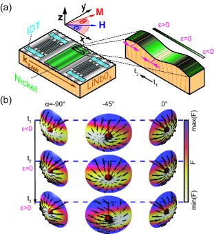
We study the hybrid device depicted schematically in Fig. 1(a). It consists of a thick polycrystalline ferromagnetic nickel film deposited onto the central part of a y-cut lithium niobate substrate. thick Aluminum interdigital transducers (IDTs) datta:SAW with a finger width of are employed to launch and detect a SAW. The complex forward transmission of the approximately long delay line is determined using vector network analysis with a time domain window to cancel the contributions of electromagnetic crosstalk and triple transit interference from the signal. For the description of the experimental and theoretical results we employ the cartesian coordinate system shown in Fig. 1(a), where is the angle between an external magnetic field applied in the Ni film plane and the SAW propagation direction . We first discuss the influence of the SAW on the magnetization vector based on magnetoelastic coupling. In the static limit, the magnetic free energy density of the Ni film normalized to the saturation magnetization is given by chikazumi:ferromagnetism
| (1) |
where with components {}. is the shape anisotropy and is a uniaxial in-plane anisotropy field along . In equilibrium, the magnetization is oriented along a minimum of . Due to the shape anisotropy, and as we only consider in the film plane here, the equilibrium orientation is in the film plane, at an angle between and .
The SAW generates an RF strain in the ferromagnetic thin film plane. Due to magnetoelasticity chikazumi:ferromagnetism , this strain results in an RF contribution to the magnetic free energy density
| (2) |
where is the magnetoelastic coupling constant and shear strains have been neglected for simplicity. The effective field acting on is given by Fidler:2000 ; Pechan:2001 , evaluated at the equilibrium orientation .
The qualitative effect of the SAW on the magnetization is illustrated in Fig. 1(b), where we exemplarily consider an in-plane magnetically isotropic nickel film (). The total magnetic free energy density is depicted by the color code in the caps close to the magnetization equilibrium position for and , and . The ”tickle field”, i.e., the components of perpendicular to , is depicted by the black arrows on top of the caps. One observes from Fig. 1(b) that the tickle field strongly depends on the external static magnetic field orientation and vanishes for and . Thus, for , the acoustic FMR signal will vanish for , resulting in a four-fold symmetry. This is in stark contrast to conventional FMR, in which the RF magnetic field is applied externally and does not depend on . Taken together, the above model suggests that the characteristic dependence on the orientation of the external static magnetic field can be used as a fingerprint to distinguish acoustically driven FMR from conventional FMR.
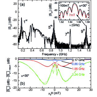
We next discuss our experimental results. Figure 2(a) shows the magnitude of the transmission measured in the nickel/lithium niobate hybrid as a function of frequency at zero external magnetic field. Several RF transmission maxima, corresponding to propagating SAWs, are observed. The first transmission maximum occurs at the SAW delay line fundamental frequency of . SAW transmission is also observed at odd harmonics, which allows choosing the magnetoelastic interaction frequency in a range from to . Here, we constrain our discussion to the fundamental frequency as well as the 5th, 9th and 13th harmonic frequency, as these frequencies exhibit the most intense SAW transmission for the chosen IDT metallization ratio of 0.5. Using appropriate IDT designs datta:SAW it is possible to excite SAWs at several almost arbitrarily chosen frequencies, or even a broad frequency range. The inset in Fig. 2(a) exemplarily shows the frequency dependence of around the 9th harmonic () for two different values of the external magnetic field. The series of transmission lobes is characteristic of a SAW delay line passband datta:SAW . As is changed from to the damping of the SAW increases by approximately . Figure 2(b) depicts the evolution of the SAW transmission as a function of magnetic field strength for a full magnetic field sweep from to and back to . The data correspond to the SAW transmission averaged over the FWHM of the central passband lobe . In addition to the hysteretic magnetization switching at already reported Feng:1982 ; Wiegert:1987 , two absorption maxima can be discerned as pronounced dips in Fig. 2(b). The latter show no hysteresis, are symmetric to zero external magnetic field, and are both present in the magnetic field up- as well as the downsweep. Furthermore, the maximal SAW attenuation increases with frequency from less than at to approximately at , and simultaneously shifts to larger . Due to the characteristic non-hysteretic behavior of the attenuation maxima together with their shift as a function of frequency, we attribute the attenuation maxima to FMR. The slight asymmetry in the attenuation maxima in Fig. 2(b) is observed for all orientations. Further work will be necessary to determine its origin.
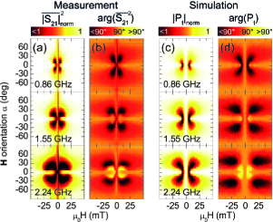
To identify the mechanism driving the FMR, a detailed study of the angular dependence is mandatory, as discussed in the context of Fig. 1(b). We thus performed a series of measurements to determine as a function of magnetic field magnitude and orientation. The orientation of the in-plane static magnetic field was varied in steps from to . Figure 3(a) shows the data obtained as a false color plot. The color code represents the normalized transmission , with black indicating maximal absorption. Figure 3(b) depicts the corresponding signal phase , setting , with black and yellow visualizing deviations of the signal phase from 90∘ (orange). As evident from Fig. 3, the SAW transmission exhibits a characteristic, approximately four-fold angular symmetry (four transmission minima as a function of for a given external magnetic field magnitude). Thus, in addition to the shift of the resonance field with frequency already discussed in the context of Fig. 2, the anisotropy of the SAW magneto-transmission exhibits the characteristic fingerprint of SAW-driven acoustic FMR. In particular, no attenuation occurs for and , as expected according to the picture shown in Fig. 1(b). The fact that the attenuation maxima are not located exactly at is due to a uniaxial in-plane magnetic anisotropy , as discussed in the following.
To model the SAW magneto-transmission, we use a Landau-Lifshitz-Gilbert (LLG) approach, taking into account RF magnetoelastic effects. We neglect spatial variations of the strains and restrict the calculations to the collective FMR mode. The LLG equation Landau:1935 ; Gilbert:2004
| (3) |
describes the evolution of the magnetization direction in an effective magnetic field , with and being the gyromagnetic ratio and the Gilbert damping parameter, respectively. We solve the LLG in a cartesian coordinate system with the first axis pointing along the equilibrium direction of , which in our case is in the film plane at an angle to the axis and the third axis pointing out-of-plane. In the following, the subscripts {1,2,3} refer to this frame of reference. Thus, , where and denote small deviations from equilibrium. The non-vanishing component of the effective RF magnetic field Fidler:2000 ; Pechan:2001 is given by
| (4) |
In contrast to classical FMR, where an external RF magnetic field is exploited to drive the resonance, Eq. 4 shows that acoustic FMR is excited by a purely internal RF magnetic field . The latter is due to RF spin mechanics, i.e., it is generated by the magnetoelastic interaction of the SAW elastic strain field with the ferromagnet. This coupling between and the SAW results in a resonant attenuation and phase shift of the SAW transmission when the condition for ferromagnetic resonance is met. We write the transmitted RF power density as
| (5) |
where the Polder susceptibility is a function of the static magnetic free energy density , is the power density transmitted off resonance and is the SAW angular frequency. The non-vanishing components of the Polder susceptibility tensor read as , and with , and . Eq. (5) corresponds to the conventional FMR formula Kobayashi:1973 , but employs the purely virtual defined in Eq. (4) instead of an externally applied, real RF magnetic field.
Figure 3(c) shows calculated using Eq. (5), with , , and along the -direction for the three frequencies investigated in the experiment. Figure 3(d) depicts the corresponding transmission phases . The simulation reproduces all the salient features observed in the experiment, in particular the angular dependence. Considering our rather simple model, the agreement is excellent. This demonstrates that the SAW absorption is indeed caused by acoustically driven ferromagnetic resonance, i.e., by RF magnetoelastic interactions, and not by conventional FMR. Moreover, it corroborates the use of a virtual, purely internal on the same footing as a real externally applied magnetic field in Eq. (5) a posteriori. We note that our damping constant is about a factor of ten larger than that expected from cavity FMR experiments Bhagat:1966 . This value was chosen to account for line broadening presumably due to the inhomogeneous tickle field periodic with the SAW wavelength at , corresponding to a wavevector . In coplanar waveguide FMR such non-uniform excitation fields are known to lead to a line broadening by 100% already for Counil:2004 . The much larger wavevectors in our case will therefore lead to considerably higher linewidths, i.e. . To circumvent such inhomogeneous broadening effects, one may miniaturize the ferromagnetic thin film to lateral dimensions much smaller than the SAW wavelength. In such samples, a determination of the influence of magnon-phonon interactions on magnetic damping should be possible.
In conclusion, we have consistently found both in experiment and in simulation that the magnetoelastic interaction of a SAW with a ferromagnetic thin film allows to excite FMR in the film. The FMR is driven acoustically in the sense that no external RF magnetic field is applied to the ferromagnet. Rather, a purely internal RF magnetic field arises due to magnetoelastic coupling between the SAW elastic strain field and the ferromagnet. Using a free energy approach as well as LLG calculations, we showed that the magnitude of the ”acoustic” RF magnetic field characteristically depends on the orientation of the magnetization. The angular dependence of the SAW transmission thus is a fingerprint of acoustic FMR, as observed in our experiments. Our experimental findings open a third alternative for the excitation of FMR, in addition to externally applied RF magnetic fields Kittel:1948 ; Bickford:1950 or the spin torque effect Slonczewski:1996 ; Myers:1999 ; Katine:2000 ; Stiles:2002 ; Zhang:2002 . More fundamentally, acoustic FMR can provide a pathway for the study of magnon-phonon interaction phenomena studied predominantly on theoretical grounds to date Tiersten:1964 ; Kobayashi:1973 ; Kobayashi:1973-1 ; Fedders:1974 , or also for mechanical spin pumping kovalev:2005 ; mosendz:2010 . The coupling between elastic and magnetic degrees of freedom will open additional channels for spin dephasing, so that the magnetization damping is linked to the magnon-phonon coupling strength. Furthermore, a detailed study of the interaction between magnonic and phononic dispersions, of the strength of the coupling, of the anticrossing of these branches and of the generation of strongly coupled elastic/magnetic states are appealing challenges for the future.
We gratefully acknowledge stimulating discussions with B. Botters, R. Huber and D. Grundler. This work is financially supported by the DFG via project nos GO 944/3-1, SFB 631 C3, and by the Cluster of Excellence Nanosystems Initiative Munich (NIM).
References
- (1) H. Zheng et al., Science 303, 661 (2004).
- (2) N. A. Spaldin and M. Fiebig, Science 309, 391 (2005).
- (3) W. Eerenstein et al., Nat. Mater. 6, 348 (2007).
- (4) C. Bihler et al., Phys. Rev. B 78, 045203 (2008).
- (5) A. W. Rushforth et al., Phys. Rev. B 78, 085314 (2008).
- (6) M. Weiler et al., New J. Phys. 11, 013021 (2009).
- (7) H. F. Tiersten, J. Math. Phys. 5, 1298 (1964).
- (8) T. Kobayashi et al., Phys. Rev. B 7, 3273 (1973).
- (9) T. Kobayashi, R. C. Barker, and A. Yelon, Phys. Rev. B 7, 3286 (1973).
- (10) P. A. Fedders, Phys. Rev. B 9, 3835 (1974).
- (11) H. Bömmel and K. Dransfeld, Phys. Rev. Lett. 3, 83 (1959).
- (12) A. K. Ganguly, J. Appl. Phys. 47, 2696 (1976).
- (13) I. Feng et al., J. Appl. Phys. 53, 177 (1982).
- (14) R. F. Wiegert and M. Levy, J. Appl. Phys. 61, 4270 (1987).
- (15) R. F. Wiegert and M. Levy, IEEE Trans. Magn. 37, 2708 (2001).
- (16) R. F. Wiegert, J. Appl. Phys. 91, 8231 (2002).
- (17) S. Datta, Surface Acoustic Wave Devices (Prentice Hall, Englewood Cliffs, 1986).
- (18) S. Chikazumi, Physics of Ferromagnetism (Oxford Univ. Press, Oxford, 1997), 2nd ed.
- (19) J. Fidler and T. Schrefl, J. Phys. D: Appl. Phys. 33, R135 (2000).
- (20) M. J. Pechan et al., J. Appl. Phys. 89, 7514 (2001).
- (21) L. Landau and E. M. Lifshitz, Phys. Z. Sowjet. 8, 153 (1935).
- (22) T. Gilbert, IEEE Trans. Magn. 40, 3443 (2004).
- (23) S. M. Bhagat, L. L. Hirst, and J. R. Anderson, J. Appl. Phys. 37, 194 (1966).
- (24) G. Counil et al., J. Appl. Phys. 95, 5646 (2004).
- (25) C. Kittel, Phys. Rev. 73, 155 (1948).
- (26) L. R. Bickford, Phys. Rev. 78, 449 (1950).
- (27) J. C. Slonczewski, J. Magn. Magn. Mater. 159, L1 (1996).
- (28) E. B. Myers et al., Science 285, 867 (1999).
- (29) J. A. Katine et al., Phys. Rev. Lett. 84, 3149 (2000).
- (30) M. D. Stiles and A. Zangwill, Phys. Rev. B 66, 014407 (2002).
- (31) S. Zhang, P. M. Levy, and A. Fert, Phys. Rev. Lett. 88, 236601 (2002).
- (32) A. A. Kovalev, G. E. W. Bauer, and A. Brataas, Phys. Rev. Lett. 94, 167201 (2005).
- (33) O. Mosendz et al., Phys. Rev. Lett. 104, 046601 (2010).