The LISA PathFinder DMU and Radiation Monitor
Abstract
The LISA PathFinder DMU (Data Management Unit) flight model was formally accepted by ESA and ASD on 11 February 2010, after all hardware and software tests had been successfully completed. The diagnostics items are scheduled to be delivered by the end of 2010. In this paper we review the requirements and performance of this instrumentation, specially focusing on the Radiation Monitor and the DMU, as well as the status of their programmed use during mission operations, on which work is ongoing at the time of writing.
pacs:
04.80.Nn, 95.55.Ym, 04.30.Nk,07.87.+v,07.60.Ly,42.60.MiKeywords: LISA, LISA Pathfinder, gravitational wave detector, charge deposition, Radiation Monitor, Data Management Unit
1 Introduction
LISA is a technologically sophisticated mission. So complex, in fact, that ESA decided to fly a precursor mission to ensure technology readiness and maturity have reached a safe status to start LISA. Launch for PathFinder is currently set for early 2013.
LISA PathFinder (LPF) has a reduced acceleration noise budget, both in magnitude and in frequency band with respect to LISA [1]:
| (1) |
in the frequency band between 1 mHz and 30 mHz.
This noise can be apportioned to different components, each of them individually interfering with the mission performance. Requirements are set on each of those so that the total sum is compatible with equation (1) [1]. Thermal, magnetic and charged particle flux are specifically monitored by dedicated hardware and software, forming what is known as the Data and Diagnostics Subsystem (DDS), which also includes the DMU (Data Management Unit), the LTP (LISA Technology Package, or mission payload) computer. The DDS has been designed and built in IEEC-CSIC in Barcelona, Spain, and Flight Models of each of its parts have been delivered, or will be by the end of 2010, after passing extensive tests to ensure their performance during mission operations.
In this paper we review the latest progress with the DDS parts, specially focusing on the Radiation Monitor and the DMU, which have been the subject of our work during the last few months. We will however give a quick summary of the other diagnostics items as well in the first sections; a more detailed description of them can be found in reference [2].
2 Thermal diagnostics
The thermal stability in the LTP Core Assembly (LCA) has to meet a very stringent requirement:
| (2) |
A set of 24 temperature sensors are scattered around the LCA which are intended to measure temperatures at as many strategic spots. More specifically, in the outer walls of the Electrode Housings of both Test Masses (TM), at both Optical Windows (OW), at the Optical Bench (OB) and in the suspension struts (SS). In order to be able to make significant measurements in an environment with such a degree of thermal stability as required by equation (2), an even more demanding requirement must be set on the performance of these sensors. This is [3]
| (3) |
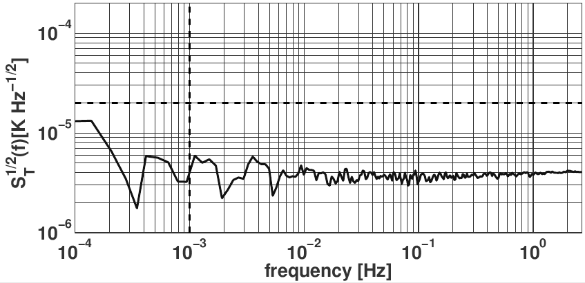
The temperature sensing in the DDS is done by means of NTC (Negative Temperature Coefficient) thermistors, because they have more pronounced slopes in the temperature–resistance plane than other devices such as Platinum resistors. In addition, an extremely quiet front-end electronics must be used to drive them and acquire data. This electronics is part of the DMU, and Figure 1 shows the performance of a differential temperature measurement between two NTCs as recorded in the latest tests done with Flight Model sensors and DMU. This was April-2010. A detail must however be clarified: because of mass and power budget limitations, not every one of the 24 thermistors can have its own electronic board; rather, they are multiplexed in six groups of four. While this makes the system globally compliant with those constraints, it introduces additional noise, as the real sampling frequency is divided by 4 in each thermistor. Therefore the multiplexed system noise is higher by a factor of 41/2 = 2 than shown in the plot. Note however that we are still fully within requirements. Actually, the (individual) NTC noise is below 10-5 K Hz-1/2 all the way down to 10-5 Hz, i.e., well within the LISA band. This means the current LTP thermal system can probably be transferred basically as is into LISA.
2.1 Precision heaters
It needs to be stressed that such marvellously working temperature sensors are not by themselves of much use for the purpose they will be embarked. As explained in the previous section, we need these monitors to record temperature fluctuations which affect the performance of the LTP. But how do we link a (known) temperature fluctuation with an (unknown) TM shake or an interferometer phase jitter? Although this link can be modelled, it has to also be established in flight by direct measurement —since the model may be inaccurate.
To the effect, a set of 14 precision heaters are also installed in the LTP at some suitable spots [4]. Their role is to inject controlled thermal signals in the system such that they are strong enough to be clearly seen in the LTP readout, i.e., with a signal-to-noise ratio around 100. Temperature measurements are taken as well and hence a relationship is established between the latter and the observed response of the interferometer and/or the Gravitational Reference Sensor (GRS). The analysis is done in frequency domain, so that a set of transfer functions is obtained relating temperature variations to LTP response. Finally, the hypothesis is made that the behaviour of the LTP is maintained when the heaters are switched off.
Heaters are driven with very low noise DMU electronics. There are two major groups of heaters: those in the GRS and those elsewhere [4]. The ones in the second group are rather conventional kapton heaters, consisting in a wire winding held together by an elastic resin. These heaters, however, cannot be attached to the walls of the Electrode Housing (EH) of the GRS due to their magnetic properties: they actually have some significant quantities of ferromagnetic elements, notably Nickel, which are likely to compromise the stability of the TM. It was therefore decided that NTCs should also be used as heaters in that part of the LTP.
These NTCs are a bit more difficult to drive than the others due to their changing electric resistance upon being heated up. Indeed, when a voltage is applied to an NTC the current through it will heat it up, hence its resistance will drop, hence the current and power it dissipates will increase. It has been shown [5] that, under suitable conditions of initial NTC temperature, thermal resistance between the heater and the attachment block, and voltage range, this process ends up in a stationary state in a matter of about 10 seconds. This is good enough for the time scales of the heating operations (normally a few thousand seconds), but the DMU has to be programmed such that these heaters be commanded to deliver the required power in the stationary state. In other words, the voltage may not be just , where is some nominal NTC resistance value, but rather , where is the NTC stationary state resistance, instead. Actually the relationship between voltage applied and stationary state power dissipation is somewhat involved:
| (4) |
where is the NTC temperature just prior to activation (measured with an adjacent sensor), is the above mentioned thermal resistance, and = is the thermistor’s temperature coefficient. The dependence of on is usually given by the Steinhart-Hart equation [6], again a somewhat involved mathematical expression.
The algebraic complexities of the above formulae make it impossible to invert equation (4) to obtain the voltage as a function of the power in a closed-form expression. This circumstance has motivated the use of Look-Up Tables (LUT) in the DMU software which commands the GRS heaters: for a given thermal resistance (measured on ground) and an NTC temperature (measured dynamically on flight), the SW looks for the tabulated power which is closest to the one required for injection, then reads off the LUT the activation voltage, and applies it [7].
3 Magnetic diagnostics
The LTP Test Masses are made of a 70 % Au + 30 % Pt alloy, a good combination to keep as low as possible their magnetic properties and, at the same time, to provide sufficient mechanical robustness to withstand launch shaking while caged. It is however impossible to avoid the presence of ferromagnetic residuals after the casting, hence some magnetic remanence will be there. Limits have been set on remnant magnetic moment and susceptibility as [2]
| (5) |
These parameters couple to the surrounding magnetic field, mostly created by spacecraft electronic boxes and other components, such as solar panels, FEEP (Field Effect Electric Propulsion, the satellite’s micro-thrusters), etc., thereby creating forces and torques on the Test Masses, and fluctuations thereof, i.e., magnetic noise. According to standard electromagnetic theory, forces and torques are respectively given by
| (6) |
and
| (7) |
The meaning of symbols in the above formulae is as follows:
| B | Magnetic induction field in the TM | |
| M | Density of magnetic moment (magnetisation) of the TM | |
| r | Vector distance to the TM centre of mass | |
| Volume of the TM | ||
| Magnetic susceptibility of the TM | ||
| Vacuum magnetic constant (410-7 m kg s-2 A-2) |
while indicates TM volume average of enclosed quantity. For example, for any magnitude , such average is defined by the volume integral
| (8) |
over the TM volume. Magnetic noise can be readily inferred from the above formulae. There is no specific requirement on either magnetic field or gradient fluctuations, there is only one on the total contribution of magnetic disturbances to the overall mission acceleration noise budget; magnetic is required to stay below 40% of that budget [1]. On the other hand, there are specific requirements on the DC values of magnetic field and gradient, which should be kept below 10 -Tesla and 5 -Tesla/m, respectively. This is because of the quadratic dependence of the force F on the magnetic field B, due to the presence of a non-zero susceptibility —see equation (7); when it comes to evaluating fluctuations, it is immediately seen that DC field values couple to gradient fluctuations, and also DC gradient values couple to field fluctuations.
Magnetic fields in the LTP are monitored by means of four tri-axial fluxgate magnetometers, located in the periphery of the LCA. These are not ideally suited to infer the magnetic field and gradient at the TMs, due to their distance to the latter. Classical interpolation methods have failed to produce acceptable results, but neural network algorithms have been developed and studied at IEEC which produce significant improvements in our ability to determine field values at the TMs [8]. The reader is also recommended to look into Marc Díaz’s contribution to this Proceedings for more in-depth analysis and details.
3.1 Alternative solutions
While it is not possible to make changes now to the general LPF plan, e.g., magnetometers cannot be replaced, it would be unwise to think of LISA carrying on board a set of a few high performance but distant and voluminous fluxgate magnetometers. Ongoing research at IEEC has revealed that alternatives to the LPF scheme seem to exist. These are based on both a new type of sensors and driving electronics. The new sensors are tiny AMR (anisotropic magneto-resistor), while the electronics resorts to periodic flipping voltages to apply set-reset signals to the devices, thereby enhancing their performance. In Figure 2 we see noise curves of various magnetic sensors and activation techniques which show the significant advantage which can be potentially drawn from the new AMRs. There are issues still to be properly addressed, perhaps most notably the possible magnetic back-action of the sensors, since they have tiny ferromagnetic cores. Analysis so far point towards a negligible such back-action, the reader will find much more detailed information in Ignacio Mateos’s contribution to this Conference Proceedings.

3.2 Control coils
Just like thermal diagnostics require precision heaters, so magnetic diagnostics require precision induction coils. Their purpose is very similar to that of the heaters, though with a difference: strong magnetic signals injected by the induction coils, together with the LTP response to them (again in the order of SNR 100) can be used to determine the remnant magnetic moment and the susceptibility of the TMs. More information can be found in [2].
4 The Radiation Monitor
LPF will be stationed for operations in a Lissajous orbit around the Earth-Sun Lagrange point L1. This is about 1.5 million kilometres from Earth, i.e., well beyond its radiation belts. The spacecraft will thus be exposed to particles in the solar wind, but also to others, mostly of galactic origin. The composition of these fluxes in charged particles is roughly 90% protons, 8% Helium ions, and 2% heavier nuclei (Carbon and higher ) and electrons. These will charge the spacecraft through both direct and indirect deposition, since secondary particles are generated as the primary ones travel across the various materials. What creates concerns about charging is actually only the TMs, as charge depositions in them generates spurious potentials, hence noise in the GRS readout due to the random character of those depositions.
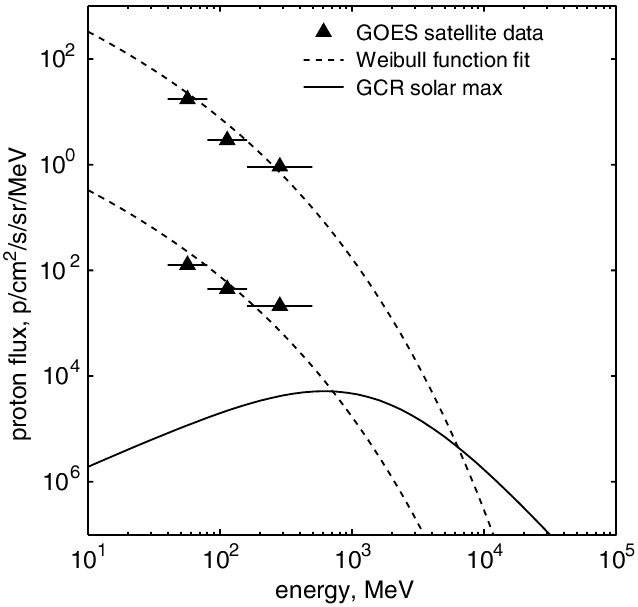
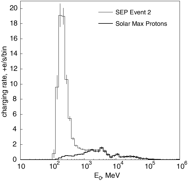
Extensive simulations done at Imperial College [9] with the public CERN tool Geant-4 show that only primary particles with energies roughly above 70 MeV can possibly make it to the TM; lower energy ones are deterred by the satellite structures surrounding the TMs, and hence can cause no harm to the experiment. The simulations also show that the charging rates of the TMs depends on whether the primary particles are Galactic Cosmic Rays (GCR) or correspond to flares in the Sun (SEP events, Solar Energetic Particles111 The solar wind contains mostly keV particles, only a relatively small fraction are above 100 MeV, hence the name SEP.). These two types of fluxes have different energy spectra, and the way to distinguish between them is therefore to do spectroscopy. Figure 3 shows quite clearly the above distinction: spectra of GCR are displayed on the left and deposition rates in the right panel. Data are due to Araújo et al [10]. See also Catia Grimani’s contribution to this volume,
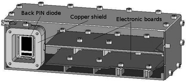
The Radiation Monitor’s role in LPF is to identify the charging rates in the TMs by short term monitoring of the charged incoming particles. For this, a sensor consisting in two PIN diodes in telescopic configuration are used. They are enclosed in a copper shielding which prevents primaries with energies above 70 MeV to reach them, thereby recreating the actual situation in the TMs, see Figure 4, left panel. The PINs are attached to electronic circuits capable of counting both single events in either diode as well as coincident events in the two of them. These coincidences are used to do spectroscopy based on the energy deposition, which is also measured. The RM data are stored in a histogram format as shown in Figure 4, right panel.
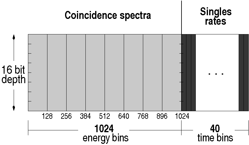
One such histogram is the RM telemetry unit. Bins are scanned and filled at 100 Hz. Data are accumulated in the DMU during 600 seconds (i.e., 10 minutes) and then sent to the On Board Computer (OBC) to be telemetered to Earth according to mission schedules. Data are subsequently analysed off-line to look for correlations with the Charge Management System, which takes much longer periods to produce data. We can thus use the RM to detect shorter term charging fluctuations as well as modulations which should be useful to more thoroughly assess the whole process [11].
At the time of writing, the LPF RM Flight Model is a few weeks from final delivery. Many tests have been done on it before that: extensive electronics tests, magnetic moment measurements, vibration, temperature stability of the RM performance and proton irradiation. The latter was carried out at the Paul Scherrer Institute (Switzerland) where a proton beam facility was used to generate low dose fluxes and assess its response for various energies and beam incidence angles. The prototype was also submitted to such test, except it was much more aggressive at that time, as many more things had to be checked then. Now we are reassured everything is in place and the test can be milder to avoid deterioration of the device before flying. Analysis of the irradiation results will soon be complete.
5 The DMU
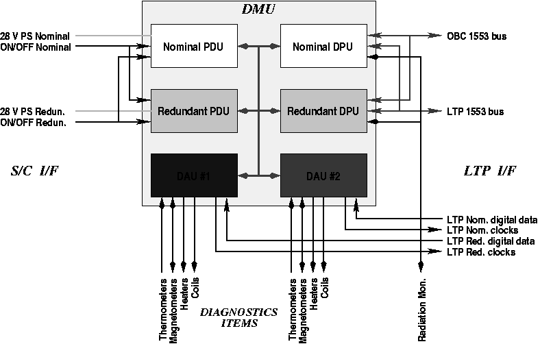
The Data Management Unit (DMU) is the LTP computer, and has been designed, developed, manufactured and delivered by IEEC, Barcelona. The latter happened on 11 February 2010. The DMU has three electronic boards: the Power Distribution Unit (PDU), the Data Acquisition Unit (DAU) and the Data Processing Unit (DPU), each of them duplicated for redundancy security. Redundancy is however not full in the DAUs, where some diagnostics items are connected to only one DAU, see Figure 5, again due to mass-energy quotas. Protection against possible DAU failure has been maximised by careful distribution of each DAU’s tasks.
The DMU fully controls of all the diagnostics items functionalities, including activation, acquisition, and telemetry as described in sections 2 and 3 above. With the exception, however, of the Radiation Monitor, which internally acquires its data and communicates with the DMU via a serial RS 422 line. But the DMU has many more interfaces with other parts of the LTP, as shown in Figure 5. Communications with the OBC and non-diagnostics parts of the LTP is done via two MIL-STD-1553 buses, respectively.
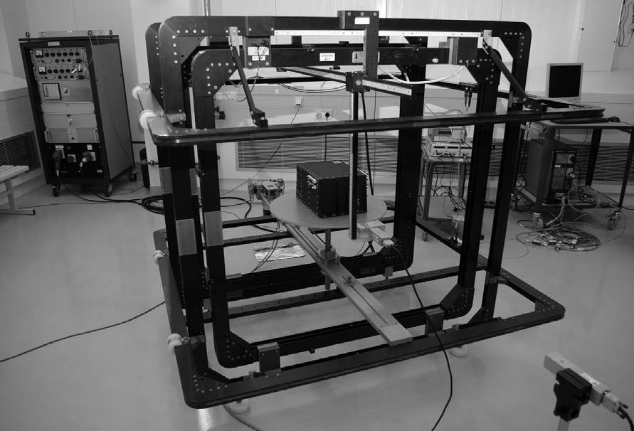
The DMU Flight Model hardware has undergone extensive testing before its formal acceptance by the Mission Architect:
-
•
All Diagnostics Items performance/functional tests
-
•
Mechanical tests: Centre of Gravity, vibration, and pyrotechnic shock
-
•
Thermal vacuum tests
-
•
Electromagnetic Compatibility tests
-
•
Dipole magnetic moment measurements
-
•
Magnetic stability tests
Some of them needed external facilities, such as magnetic tests done at ESTEC (see Figure 6), and EMC tests at a local industrial company. All the above tests, however, have also been passed by the rest of the DDS hardware, they are indeed not specific to the DMU.
5.1 The DMU Software
The DMU requires software to implement its functionalities and to communicate with its various interfaces. This software has been created from scratch at IEEC, too, and has two main bodies: the Boot Software (BSW) and the Application Software (ASW).
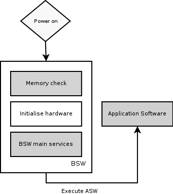
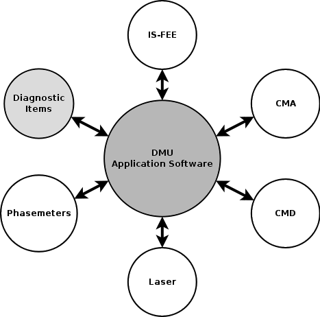
The BSW is a minimal, non-real time operating system, which occupies 61 kilobytes of memory. It contains some 30 000 lines of code, plus about 1 000 of Assembler code, and it was eventually burnt to a PROM, of course after extremely rigorous tests were passed, as the PROM cannot be either rewritten or replaced. The BSW starts the DMU and acts as scheduler, interrupt control and error detection and correction. A most important task for the mission which is also in charge of the BSW is to load the ASW, which understands and executes all the telecommands which are received from the Mission Operation Centre (MOC) following the mission Master Plan. The BSW can also patch the ASW should there be an upgrade deemed necessary for the continuation of the mission operations. The BSW has long been burnt to an FM PROM, hence is fully ready for flight.
The ASW is built on top of RTEMS (Real-Time Executive for Multiprocessor Systems), a real-time operating system, in order to cope with the hard real-time constraints (i.e. task deadlines must be met on time) of the mission. The ASW, as already mentioned, manages all the scientific and technological functions of the DMU. It supports real time tasks up to a maximum frequency of 100 Hz, and is encoded in some 70 000 lines of code, plus 300 of Assembler. In addition, it sends telemetry to the OBC via a MIL-STD-1553 bus. The ASW is stored in EEPROM (Electrically Erasable Programmable Read-Only Memory), which makes possible to receive upgrades from ground if necessary. It is executed from RAM. Stress tests done on the ASW show that it produces a maximum CPU load of 86%, therefore a bit tight on margin. Work is in progress to bring down that ratio by a few percentile points.
In addition to the mentioned stress tests, the ASW has undergone unit testing and validation, the latter by an independent entity which produced test scripts to check nominal test cases. Errors were filed and reported for debugging. The latest validated version is 2.3. ASW 2.4 was released in mid August 2010, with all functionalities in it. By the end of 2010 a validated and optimised version of ASW 2.4 will be ready.
The SW is a dynamic component of the DMU, and work on it is therefore envisaged all the way to mission completion.
6 Conclusions
We have briefly reviewed here the essential parts, as well as their functions, of the DDS. As shown, the Spanish hardware contribution to LPF is really complete, up to minor changes/details. The IEEC team keeps still active, and will be until the end of the mission. New tasks, not reported here, include the preparation of the mission operations, software (not to be confused with the DMU software) modelling of the system response to validate the PORs (Payload Operations Requests) which constitute the basis for the entire mission Experiment Master Plan, and which are being prepared in the Science and Technology Operations Centre (STOC) in ESAC, near Madrid. In addition, on-line response and off-line data analysis of the mission yield has a lot to do with the diagnostics subsystem, hence IEEC is very actively involved in these matters, too.
References
References
- [1] Vitale S 2005, Science Requirements and Top-level Architecture Definition for the LISA Technology Package (LTP) on Board LISA Pathfinder (SMART-2), report no. LTPA-UTN-ScRD-Iss003-Rev1
- [2] Cañizares et al 2009 Classical and Quantum Gravity 26, 094005
- [3] Sanjuán J, Lobo A, Nofrarias M, Ramos-Castro J and Riu P 2007 Rev Sci Instr 78, 104904
- [4] Lobo A 2010, LTP thermal response to periodic signals injected by heaters, report no. S2-IEC-TN-3059
- [5] Sanjuán J 2009, Development and validation of the thermal diagnostics instrumentation in LISA Pathfinder, PhD Thesis, Barcelona, Appendix B
- [6] Steinhart JS and Hart SR 1968, Calibration curves for thermistors, Deep Sea Res. 15, 497
- [7] Conchillo A and Lobo A, 2010 LTP Electrode Housing Heaters commanding, report no. S2-IEC-TN-3080
- [8] Díaz-Aguiló M, García-Berro E and Lobo A, 2010 Classical and Quantum Gravity 27, 035005
- [9] Wass PJ, Araújo HM, Shaul DNA and Sumner TJ 2005 Class Quantum Grav 22 S311
- [10] Araújo HM et al 2005 Astroparticle Physics 22, 451
- [11] Shaul D, Sumner T and Lobo A 2008, Analysis of Data from the Radiation Monitor on LISA Pathfinder, report no. S2-ICL-TN-3019