Quantifying the Stacking Registry Matching in Layered Materials
Abstract
A detailed account of a recently developed method [Marom et al., Phys. Rev. Lett. 105, 046801 (2010)] to quantify the registry mismatch in layered materials is presented. The registry index, which was originally defined for planar hexagonal boron-nitride, is extended to treat graphitic systems and generalized to describe multi-layered nanotubes. It is shown that using simple geometric considerations it is possible to capture the complex physical features of interlayer sliding in layered materials. The intuitive nature of the presented model and the efficiency of the related computations suggest that the method can be used as a powerful characterization tool for interlayer interactions in complex layered systems.
I Introduction
Single layers of atomically thin molecular structures have attracted vast attention in the past few years. Most commonly, they appear in quasi-one dimensional Iijima1991 ; Tenne1992 ; Rubio1994 ; Chopra1995 ; Loiseau1996 ; Tenne2004 ; Tenne2006 ; Golberg2007 ; saito_book ; dress-book and quasi-two dimensional Novoselov2004 ; Novoselov2005 ; Zhang2005 ; Berger2006 ; Zhi2009 ; Li2009 ; Bunch2007 ; Geim2007 forms. The physical properties of these unique structures depend on their specific geometry and chemical composition being organic, Iijima1991 ; saito_book ; dress-book inorganic, Tenne1992 ; Tenne2004 ; Tenne2006 ; Rubio1994 ; Chopra1995 ; Loiseau1996 ; Novoselov2005 ; Golberg2007 ; Zhi2009 ; Li2009 or mixed. Stephan1994 ; Miyamoto1994_I ; Miyamoto1994_II ; Weng-Sieh1995 ; Redlich1996 ; Terrones1996 ; Suenaga1997 ; Blase1997 ; Zhang1997 ; Yap2009 ; Ci2010 ; Rubio2010 When stacked together to form multi-layered structures, the physical properties of the individual layers may be considerably altered via interlayer interactions. Tanaka1997 ; Kwon1998 ; Palser1999 ; Paulson2000 ; Liu2003 ; Zhang2004 ; Kolmogorov2005 ; Novoselov2006 ; McCann2006 ; Ooi2006 ; Koskilinna2006 ; Charlier2007 ; Graf2007 ; Nagapriya2008 ; Marom2010 Due to the different nature of the intra- and inter-layer interactions, the resulting layered systems often present highly anisotropic properties. Within each layer covalent bonding usually results in relatively high strength and stiffness saito_book ; dress-book ; Yakobson2001 ; Golberg2007 along the direction of the layer and, in some cases, in efficient electronic saito_book ; dress-book ; Novoselov2004 ; Morozov2008 and heat Berber2000 ; Che2000 ; Tang2006 ; Balandin2008 ; Ghosh2008 ; Morooka2008 ; Ghosh2009 ; Hu2009 ; Lan2009 ; Jiang2009 ; Ouyang2009 ; Xu2009 ; Ouyang2010 transport. In contrast, between the layers long-range dispersion and electrostatic interactions produce weaker and more flexible mechanical properties Cumings2000 ; Kolmogorov2000 ; Zheng2002 ; Legoas2003 ; Fennimore2003 ; Deshpande2006 and result in reduced transport capabilities.
An important factor governing the physical properties of multi-layered materials is the registry matching between the layers. Depending on the nature of the interlayer interactions, different layered materials present different optimal stacking modes. As an example, the polar nature of the interlayer B-N covalent bond in hexagonal boron-nitride (-BN) results in considerable Coulomb interactions between atomic sites belonging to different layers. These, in turn, dictate an optimal stacking mode, where a boron(nitrogen) atom in one layer resides above a nitrogen(boron) atom in its adjacent layers (see Fig. 1). Graphite is iso-electronic to -BN and has the same hexagonal structure within each layer. It is therefore tempting to assume that both systems present a similar optimal stacking mode. Nevertheless, due to the lack of bond polarization in the homo-nuclear intralayer covalent bonds of graphene the dominant interlayer interactions in graphite and in few-layered graphene (FLG) are dispersion forces. These, in turn, lead to an optimal stacking mode, where a carbon atom in one graphene layer resides on top of a hollow site of the corresponding adjacent layers. The picture becomes even more complicated when considering multi-walled nanotubes. In such systems, apart from the specific chemical composition of the nanotube, which dictates the nature of the interlayer interactions, curvature differences and different rolling orientations (chiral angles) of adjacent layers result in complex registry matching and mismatching patterns often regarded as Moiré fringes. Nagapriya2008
It is therefore clear that registry matching plays an important role in dictating the electronic properties of layered materials and in the interlayer sliding physics of such systems. Drexler1986 ; Drexler1987 ; Mate1987 ; Drexler1992 ; Merkle1993 ; Falvo1998 ; Buldum1999 ; Schall2000 ; Yu2000 ; Liu2003 ; Rivera2003 ; Zhang2004 ; Zou2006 ; Marom2010 Nevertheless, previous studies concerning such effects have regarded the registry matching in qualitative terms labeling it as “bad”, “good”, or “optimal” according to the relative energetic stability of the different stacking modes as calculated by either force fields Kolmogorov2000 ; Zhang2007 or via electronic structure theories. Liu2003 ; Carlson2007
Recently, a quantitative measure of the registry matching in planar -BN was proposed. Marom2010 Based on intuitive geometrical considerations and common knowledge regarding the nature of the interlayer interactions in -BN, a simple model was derived, which predicts the relative stability of different stacking modes. It was shown that the main features of the interlayer sliding physics in this material can be captured by this simplified model thus shedding light on the main factors that govern this complex process. It is the purpose of this paper to give a detailed account of this registry index model, extending it to other planar layered materials such as graphite, and generalizing its applicability to multi-walled nanotube structures.
II Registry index in -BN
In order to define a quantitative measure of the registry mismatch in planar -BN it is important to understand the nature of the interlayer interactions in this system. Three important forces should be taken into account:
-
1.
Dispersion interactions: Van der Waals-London forces play a central role in the physics of molecular stacking. While being weaker than the intralayer covalent bonding, these induced dipole-dipole interactions are responsible for anchoring the different layers of a multi-layered material at the appropriate interlayer distance. Marom2010 Nevertheless, it was recently shown that dispersion forces are relatively insensitive to the specific interlayer arrangement of different stacking modes in -BN and thus have little effect on the interlayer sliding potential. Marom2010
-
2.
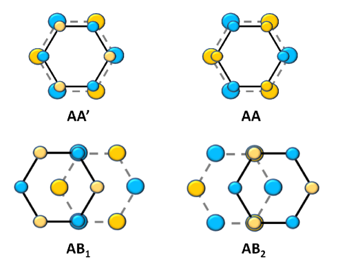
Electrostatic interactions between ionic cores: The dominant factor governing the interlayer sliding potential of -BN are electrostatic attractions and repulsions between the partially charged atomic centers on adjacent layers. Due to the difference in electronegativity of the two atoms, the boron bears a partial positive charge whereas the nitrogen has a partial negative charge. Yamamura1997 ; Liu2003 ; Marom2010 Based on these observations and on basic electrostatic considerations, one may deduce that optimal registry is achieved at the mode which maximizes the interlayer N-B Coulomb attractions and minimizes the corresponding B-B and N-N repulsions (see upper left panel of Fig. 1). Similarly, the worst stacking mode is the mode, where the -BN sheets are completely eclipsed and Coulomb repulsions between atomic centers are maximal (upper right panel of the figure).
-
3.
Charge densities overlap: Another factor that may influence the relative stability of different stacking modes is the electrostatic and Pauli repulsion due to partial overlap of the electron densities surrounding the boron and nitrogen atomic centers. Yamamura1997 ; Liu2003 ; Barreiro2008 ; Marom2010 The electron cloud associated with the boron atom is smaller than that of the nitrogen atom. one may therefore expect that the stacking mode with eclipsed boron atoms (lower left panel of Fig. 1), will be more energetically favorable than the corresponding mode with eclipsed nitrogen atoms (lower right panel of the figure). Interestingly, though the interlayer electron densities overlap is small Yamamura1997 it seems to have a considerable effect on the relative stability of the and stacking modes. Liu2003 ; Marom2010 ; Schon2010
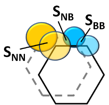
Having identified the main interactions involved in -BN interlayer coupling we may now turn to define a quantitative measure of the registry matching in this system. Similar to the total energy of the system, we are interested in a simple numerical index which will obtain a minimum value for the optimal stacking mode and a maximum value for the worst mode. To this end, we ascribe to each atom in the unit cell a circle centered around its position (see Fig. 2). Focusing on two adjacent layers, we see that the projection of a circle assigned to a specific atom located on one of the layers may overlap with circles associated with atoms of the same and/or opposite types on the other layer. We mark by the overlaps between two such circles, one associated with an atom on one layer and the other with a atom on the second layer, and being either B or N. It is now clear that the sum complies with our requirement of obtaining a minimum(maximum) value at the () stacking mode, where is maximal(minimal) and and are minimal(maximal). By normalizing this sum to be limited to the range [0,1] we obtain the registry index () for -BN:
| (1) |
Here, and are the corresponding overlaps at the and stacking modes, respectively.
This definition was obtained based on the knowledge that in -BN perfect(worst) registry is achieved at the () stacking mode due to electrostatic interactions between partially charged atomic centers. As stated above, the effect of interlayer overlap of charge densities influences the relative stability of the and configurations. In order to take this into account we assign different radii to circles associated with boron () and nitrogen () atoms. This may be viewed as a simplified representation of the difference in atomic radii between the partially negatively charged nitrogen and positively charged boron atoms. For simplicity, we fix the circle associated with the nitrogen atom to half the B-N bond length, and use the ratio as a free parameter. By choosing , obtains a lower value for the stacking mode with respect to the mode thus reproducing the physical requirement.
It is now possible to plot the at different stacking modes and compare the resulting surface obtained from simple geometric considerations with the sliding energy surface obtained from advance electronic structure calculations. Such a comparison was recently presented, Marom2010 showing a remarkable agreement between density functional theory (DFT) results obtain via the PBE density functional approximation pbe augmented with the Tkatchenko- Scheffler Van der Waals correction Tkatchenko2009 ; Marom2010_II and the model with . This exemplifies the fact that the -BN sliding process is governed by registry mismatch via electrostatic interactions and validates our assumption regarding the choice of different boron and nitrogen circle radii within the model. We therefore conclude that the , as defined above, can be used to characterize the different stacking modes of -BN. The question arises whether this simple geometric model can be extended to treat other layered materials such as graphite, and generalized to more complex structures such as nanotubes. Should the answer to this question be positive, one would be able to gain valuable physical intuition regarding such layered materials and characterize their relative interlayer configurations at a fraction of the computational cost of current electronic structure methods.
A clue to the answer to this question can be found in related recent studies using geometric considerations for the description of halogen atoms and rare gases adsorbed on (111) metal surfaces. Tkatchenko2006 ; Tkatchenko2006_II In what follows we show how the current model can be extended and generalized as suggested above.
III Registry index in graphitic materials
We start by showing that the model is not limited to the case of -BN and can be extended to treat other planar layered materials. We consider the case of graphite or FLG. As stated above, because of the homo-nuclear nature of the bonds in these systems no charge polarization occurs. Therefore, the main factors governing the sliding physics are dispersion forces and overlap of charge densities. Due to the lack of electrostatic forces, the stacking mode, which is equivalent to the stable mode in -BN, is found to be a maximum on the interlayer potential energy surface. Furthermore, the configuration, which minimizes charge densities overlap, is the optimal stacking mode of graphite. Interestingly, the interlayer distance, which is mostly influenced by dispersion interactions, Rydberg2003 ; Akdim2003 ; Ortmann2006 ; Marini2006 ; Spanu2009 ; Pakarinen2009 ; Marom2010 ; Marom2010_II is found to be very similar to that of -BN (3.35 vs. 3.33 in -BN).
Based on these observations one can now extend the registry index definition to treat graphitic materials. The graphitic should obtain a minimum value for the optimal stacking mode of graphene and a maximum value for the worst mode of this system. As for the case of -BN, we ascribe to each atom in the unit cell a circle of radius centered around its position, where is the intralayer carbon-carbon covalent bond length. The overlap between two such circles, one associated with a carbon atom on one layer and the other with a carbon atom on the second layer, is then marked by . Naturally, if the is chosen to be proportional to it will comply with the requirement of obtaining a minimum(maximum) value at the () stacking mode. By normalizing to be limited to the range [0,1] we obtain the following definition:
| (2) |
Here, and are the overlaps at the and stacking modes,respectively.
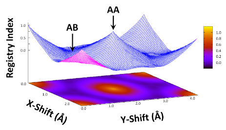
In Fig. 3 the registry index surface is presented as a function of relative interlayer sliding parallel to the basal planes of a bilayer graphene system. Comparing to recent molecular dynamics Zhang2007 and dispersion-augmented tight-binding calculations, Carlson2007 it is found that the landscape fully captures all the important features of the interlayer sliding physics of graphene. Furthermore, our results are consistent with recent experimental and theoretical investigations showing an orientation dependent sliding resistance in graphitic systems. Dienwiebel2004 ; Filippov2008 This proves that the concept is of general nature and can be readily extended to characterize the interlayer interactions in a variety of layered materials. We now turn to describe how this model can be further generalized to treat more complex structures.
IV Registry index in multi-walled nanotubes
Planar layered materials usually have a compact unit cell, which can be readily treated using standard electronic structure methods within periodic boundary conditions calculations. On the other hand, despite their reduced dimensionality, even achiral nanotubes present relatively large unit cells. This is especially true in the case of multi-walled nanotubes (MWNTs) where often one finds that, apart from the smallest bilayer systems, they are beyond the reach of state-of-the-art electronic structure methods. It is therefore desirable to generalize the defined above to treat tubular structures. Once such a generalization is established, it can be used as an efficient and reliable characterization tool for the relative stability of different inter-tube configurations.
Since nearest neighboring layers interactions are the most important factors governing the relative arrangement of the different layers within a MWNT, we generalize the to the case of double-walled nanotubes (DWNT). This allows the investigation of the isolated layer-layer interactions, which are at the basis of the multi-layered system behavior.
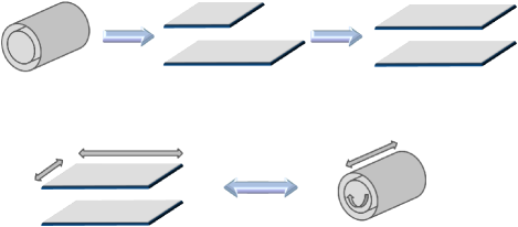
The procedure to calculate the in DWNTs is schematically presented in Fig. 4. We start by cutting the two layers along a given line parallel to the axis of the tube. Next the layers are unrolled to form planar sheets of different width. Then, the narrower sheet (unrolled inner tube) is stretched to match the width of the wider sheet (unrolled outer tube), thus taking into account the effect of curvature on the registry mismatch between the two layers. Finally, circles are placed around the atomic centers of the two layers and the is calculated using Eq. 1 (or Eq. 2) for different interlayer shifts parallel to the basal planes of the two layers. The resulting surface corresponds to relative telescoping and rotation of the two tubes within the DWNT.
Similar to the case of -BN, we can now compare the surfaces to the results obtained by DFT calculations. To this end, we perform a set of DFT calculations with the Gaussian suite of programs. gdv_short ; Gaussian The local spin density (LSDA), PBE, pbe and HSE06 Heyd2003 ; Heyd2006 exchange-correlation functional approximations are used together with the double- polarized 6-31G** Gaussian basis set Hariharan1973 . As discussed above, Dispersion interactions play a major role in anchoring the layers of -BN at the appropriate interlayer distance. Nevertheless, in the case of DWNTs, the interlayer distance is fixed by the differences of curvature between the two tubes which are set by the tubes indices. Hence, the effects of dispersion interactions on the interlayer sliding energy, which have been shown to be of minor importance in -BN, Marom2010 are neglected in the present work.
Results for three representative double-walled boron-nitride nanotubes (DWBNNT) are presented: , , and , where the notation stands for an inner tube placed within an outer tube. Unlike the case of planar -BN, DWNTs present a wide range of possible structures. The two tubes may differ in chiralities, a factor that may considerably alter their registry matching and result in orders-of-magnitude differences in their sliding energy corrugation. Interestingly, even for achiral tubes of the same kind (armchair or zigzag) two types of systems can be constructed: the first (type-I) resulting from rolling two -BN sheets in the stacking mode, and the other (type-II) resulting from rolling two stacked -BN layers. It should be noted that one such achiral DWNT may be obtained from its counterpart by switching the identities of the boron and nitrogen atoms in one of the layers. As shown below, once the chiralities and types of the two tubes are set, changing diameters of the tubes, even while fixing the inter-tube distance, has remarkable impact on the registry matching between the layers and their sliding energy surface corrugation.
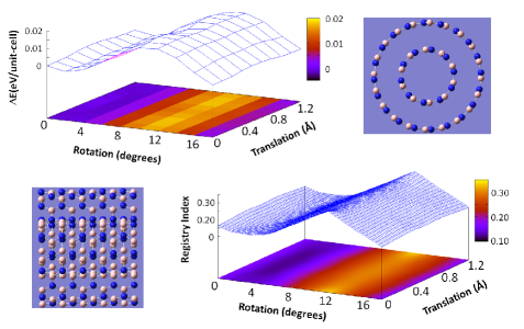
In Fig. 5 the results for the type-I system are presented. The tubes are formed by rolling two stacked layers, while fixing the B-N distance to be 1.44 . No geometry optimizations are performed. The resulting distance between the tubes is 3.44 which is similar to the equilibrium interlayer distance of -BN of 3.33 . Solozhenko1995 In the upper left panel of the figure results obtained at the PBE/6-31G** level of theory are presented. Similar results have been obtained using the LSDA and HSE06 functionals (not shown). The interlayer potential energy is found to be much more sensitive to relative rotations of the two armchair tubes than to telescoping parallel to the tubes axis. The corrugation energy, which is defined as the maximal amplitude of energy changes between different interlayer relative positions, is found to be eV/unit-cell. The corresponding surface presented in the lower right panel of the figure reproduces all of these effects while capturing even the fine details of the sliding energy surface landscape.
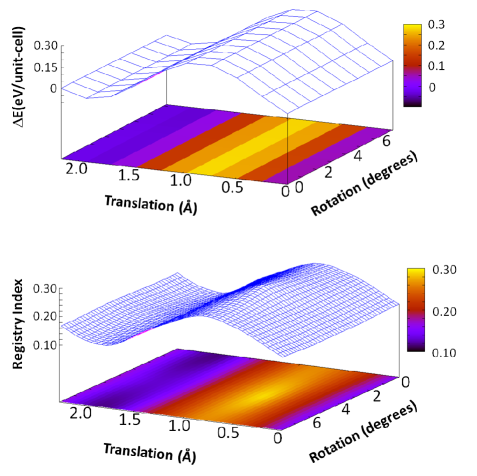
Fig. 6 presents similar results, obtained at the LSDA/6-31G** level of theory, for the type-I zigzag DWNT system. As can be seen from the upper left panel, the sliding energy surface is very similar to that obtained for the (5,5)@(10,10) armchair system. Two important differences are apparent: (i) the role of the axes is interchanged (ii) the corrugation energy for the zigzag system is found to be an order of magnitude larger than that of the armchair system. The reason for the latter difference is the smaller interlayer distance of 3.18 in the zigzag DWNT system. Nevertheless, as in the case of the armchair DWNT, the landscape fully captures all the details of the sliding energy surface obtained via DFT calculations.
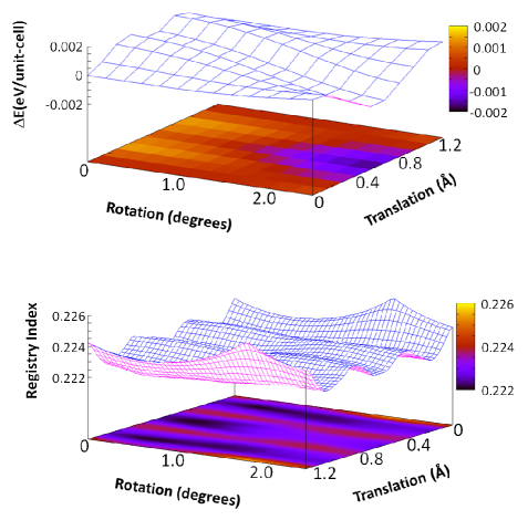
To exemplify the complexity of the sliding physics of DWBNNT systems, Merkle1993 the is considered as well. This armchair DWNT has the same interlayer distance as the system considered above. One may naively expect that the sliding energy landscape of the two systems, which have the same chirality, type, and interlayer distance, would be similar. As can be seen in the left panel of Fig. 7, this is not the case. The Corrugation energy of the is found to be an order of magnitude smaller than that of its counterpart. In fact, the energy differences between relative tube positions are calculated to be smaller than eV/unti-cell, which is beyond the accuracy of our DFT calculations. Accordingly, the agreement between the landscape (right panel of the figure) and the DFT results is not as good as those obtained for the and systems. Consistent with the reduction in the corrugation energy, the magnitude of the variations is reduces by more than an order of magnitude as well. It should be stated that the remains a valid quantity to describe the registry matching in this system. Furthermore, the amplitude of the variations may serve as an indication to the ability of DFT calculations to accurately describe the interlayer sliding landscape. It remains to be shown whether in such cases of extremely small corrugation energy the sliding physics is still dominated by the registry mismatch. An answer to this question can be given only with more accurate electronic structure calculations including the detailed effects of dispersion interactions, which may have an important contribution in these situations. Shtogun2010 ; Tkatchenko2007
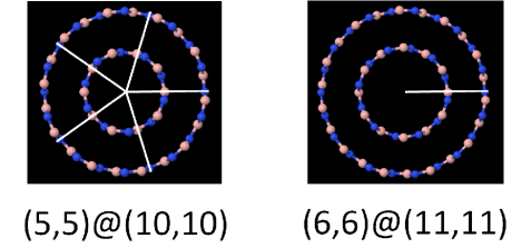
In order to better understand these differences in the corrugation energy and variations between the (5,5)@(10,10) and (6,6)@(11,11) DWBNNT we take a closer look at their symmetry characteristics. We choose an inter-tube arrangement which has a perfect on-top stacking between a given boron atom on one wall and a nitride atom on the other wall (see white lines in Fig. 8). It is now possible to define a recurrence frequency as the number of times such an on-top stacking appears along the tube circumference at that given geometry. Since a boron-nitride nanotube has a -fold rotational symmetry around the axis of the tube, the recurrence frequency of a system is given by , where stands for the greatest common divisor. For the two armchair DWNTs considered above, the recurrence frequencies are and for the and systems, respectively. Naturally, as the recurrence frequency grows, the (and the total energy) of the on-top configuration decreases, and the corrugation of the sliding energy surface increases, explaining why the system presents a considerably higher corrugation energy than the DWBNNT.
Similar considerations can be used to characterize DWNT of other chiralities showing the sensitivity of the sliding energy surface of a DWBNNT to the specific identity of its layers. Nevertheless, the extension of the model to treat tubular structures proves to be a reliable tool for the quantification of the registry matching between the layers. Therefore, it can be used to characterize the interlayer potential and identify optimal interlayer configurations of very large multi-walled nanotubes that are beyond the reach of current DFT calculations.
V Summary
A new methodology to quantify the registry matching in layered materials, based on simple geometric considerations, was presented. The registry index, which was originally developed to describe the stacking registry in planar -BN, was extended to treat graphitic materials and generalized to describe multi-walled nanotubes. Even in the challenging case of double-walled boron-nitride nanotubes, the model was able to capture the important physical features of the interlayer sliding up to fine details. This marks the method as a powerful characterization tool for interlayer interactions in complex layered systems while giving intuitive insights regarding the nature of the interlayer couplings.
VI Acknowledgments
The author would like to thank Prof. Leeor Kronik and Prof. Ernesto Joselevich from the Weizmann Institute of Science, Dr. Alexandre Tkatchenko from the Fritz-Haber Institute, Dr. Noa Marom from the University of Texas at Austin, and Prof. Michael Urbakh from Tel-Aviv University for many intriguing discussions on the subject. This work was supported by the Israel Science Foundation under grant No 1313/08 , and the Center for Nanoscience and Nanotechnology at Tel-Aviv University. The research leading to these results has received funding from the European Community’s Seventh Framework Programme FP7/2007-2013 under grant agreement No 249225.
References
- (1) S. Iijima, Nature 354, 56 (1991).
- (2) R. Tenne, L. Margulis, M. Genut, and G. Hodes, Nature 360, 444 (1992).
- (3) A. Rubio, J. L. Corkill, and M. L. Cohen, Phys. Rev. B 49, 5081 (1994).
- (4) N. G. Chopra et al., Science 269, 966 (1995).
- (5) A. Loiseau et al., Phys. Rev. Lett. 76, 4737 (1996).
- (6) R. Tenne and C. N. R. Rao, Phil. Trans. R. Soc. Lond. A 362, 2099 (2004).
- (7) R. Tenne, Nat. Nanotech. 1, 103 (2006).
- (8) D. Golberg, Y. Bando, C. C. Tang, and C. Y. Zhi, Adv. Mater. 19, 2413 (2007).
- (9) R. Saito, G. Dresselhaus, and M. S. Dresselhaus, Physical Properties of Carbon Nanotubes (Imperial College Press, London, 1998).
- (10) M. S. Dresselhaus, G. Dresselhaus, and P. Avouris, Topics in Applied Physics, Vol. 80 (Springer, Heidelberg, 2001).
- (11) K. S. Novoselov et al., Science 306, 666 (2004).
- (12) K. S. Novoselov et al., Proc. Natl. Acad. Sci. 102, 10451 (2005).
- (13) Y. Zhang, Y.-W. Tan, H. L. Stormer, and P. Kim, Nature 438, 201 (2005).
- (14) C. Berger et al., Science 312, 1191 (2006).
- (15) C. Y. Zhi et al., Adv. Mater. 21, 2889 (2009).
- (16) C. Li et al., Nanotechnology 20, 385707 (2009).
- (17) J. S. Bunch et al., Science 315, 490 (2007).
- (18) A. K. Geim and K. S. Novoselov, Nat. Mat. 6, 183 (2007).
- (19) O. Stephan et al., Science 266, 1683 (1994).
- (20) Y. Miyamoto, A. Rubio, M. L. Cohen, and S. G. Louie, Phys. Rev. B 50, 4976 (1994).
- (21) Y. Miyamoto, A. Rubio, S. G. Louie, and M. L. Cohen, Phys. Rev. B 50, 18360 (1994).
- (22) Z. Weng-Sieh et al., Phys. Rev. B 51, 11229 (1995).
- (23) P. Redlich et al., Chem. Phys. Lett. 260, 465 (1996).
- (24) M. Terrones et al., Chem. Phys. Lett. 257, 576 (1996).
- (25) K. Suenaga et al., Science 278, 653 (1997).
- (26) X. Blase, J.-C. Charlier, A. De-Vita, and R. Car, Appl. Phys. Lett. 70, 197 (1997).
- (27) Y. Zhang, H. Gu, K. Suenaga, and S. Iijima, Chem. Phys. Lett. 279, 264 (1997).
- (28) Yap, Y. K. (ed.) B-C-N Nanotubes and Related Nanostructures (Lecture Notes in Nanoscale Science and Technology, Springer, 2009).
- (29) L. Ci et al., Nature Materials 9, 430 (2010).
- (30) A. Rubio, Nature Materials 9, 379 (2010).
- (31) K. Tanaka et al., Carbon 35, 121 (1997).
- (32) Y.-K. Kwon and D. Tománek, Phys. Rev. B 58, R16001 (1998).
- (33) A. H. R. Palser, Phys. Chem. Chem. Phys. 1, 4459 (1999).
- (34) S. Paulson et al., Science 290, 1742 (2000).
- (35) L. Liu, Y. P. Feng, and Z. X. Shen, Phys. Rev. B 68, 104102 (2003).
- (36) S. Zhang, W. K. Liu, and R. S. Ruoff, Nano Lett. 4, 293 (2004).
- (37) A. N. Kolmogorov and V. H. Crespi, Phys. Rev. B 71, 235415 (2005).
- (38) K. S. Novoselov et al., Nat. Phys. 2, 177 (2006).
- (39) E. McCann and V. I. Fal’ko, Phys. Rev. Lett. 96, 086805 (2006).
- (40) N. Ooi, A. Rairkar, L. Lindsley, and J. B. Adams, J. Phys.: Condens. Mater. 18, 97 (2006).
- (41) J. O. Koskilinna, M. Linnolahti, and T. A. Pakkanen, Trib. Lett. 24, 37 (2006).
- (42) J.-C. Charlier, X. Blase, and S. Roche, Rev. Mod. Phys. 79, 677 (2007).
- (43) D. Graf et al., The European Physical Journal - Special Topics 148, 171 (2007), 10.1140/epjst/e2007-00237-1.
- (44) K. S. Nagapriya et al., Phys. Rev. B 78, 165417 (2008).
- (45) N. Marom et al., Phys. Rev. Lett. 105, 046801 (2010).
- (46) B. I. Yakobson and P. Avouris, Topics in Applied Physics 80, 287 (2001).
- (47) S. V. Morozov et al., Phys. Rev. Lett. 100, 016602 (2008).
- (48) S. Berber, Y.-K. Kwon, and D. Tománek, Phys. Rev. Lett. 84, 4613 (2000).
- (49) J. Che, T. Cagin, and W. A. Goddard-III, Nanotechnology 11, 65 (2000).
- (50) C. Tang et al., J. Phys. Chem. B 110, 10354– (2006).
- (51) A. A. Balandin et al., Nano Lett. 8, 902 (2008).
- (52) S. Ghosh et al., Appl. Phys. Lett. 92, 151911 (2008).
- (53) M. Morooka, T. Yamamoto, and K. Watanabe, Phys. Rev. B 77, 033412 (2008).
- (54) S. Ghosh, D. L. Nika, E. P. Pokatilov, and A. A. Balandin, New J. Phys. 11, 095012 (2009).
- (55) J. Hu, X. Ruan, and Y. P. Chen, Nano Lett. 9, 2730 (2009).
- (56) J. Lan, J.-S. Wang, C. K. Gan, and S. K. Chin, Phys. Rev. B 79, 115401 (2009).
- (57) J.-W. Jiang, J.-S. Wang, and B. Li, Phys. Rev. B 79, 205418 (2009).
- (58) T. Ouyang, Y. P. Chen, K. K. Yang, and J. X. Zhong, Europhys. Lett. 88, 28002 (2009).
- (59) Y. Xu, X. Chen, B.-L. Gu, and W. Duan, Appl. Phys. Lett. 95, 233116 (2009).
- (60) T. Ouyang et al., Nanotechnology 21, 245701 (2010).
- (61) J. Cumings and A. Zettl, Science 289, 602 (2000).
- (62) A. N. Kolmogorov and V. H. Crespi, Phys. Rev. Lett. 85, 4727 (2000).
- (63) Q. Zheng and Q. Jiang, Phys. Rev. Lett. 88, 045503 (2002).
- (64) S. B. Legoas et al., Phys. Rev. Lett. 90, 055504 (2003).
- (65) A. M. Fennimore et al., Nature 424, 408 (2003).
- (66) V. V. Deshpande et al., Nano Lett. 6, 1092 (2006).
- (67) Drexler K. E. 1986 Engines of Creation (New York: Doubleday).
- (68) Drexler K. E. 1987 Nanomachinery: atomically precise gears and bearings IEEE Micro Robots and Teleoperators Workshop (Hyannis, 1987).
- (69) C. M. Mate, G. M. McClelland, R. Erlandsson, and S. Chiang, Phys. Rev. Lett. 59, 1942 (1987).
- (70) Drexler K. E. 1992 Nanosystems: Molecular Machinery, Manufacturing and Computation (New York: Wiley).
- (71) R. C. Merkle, Nanotechnology 4, 86 (1993).
- (72) M. R. Falvo et al., Nature 397, 236 (1998).
- (73) A. Buldum and J. P. Lu, Phys. Rev. Lett. 83, 5050 (1999).
- (74) J. D. Schall and D. W. Brenner, Molecular Simulation 25, 73 (2000).
- (75) M.-F. Yu, B. I. Yakobson, and R. S. Ruoff, J. Phys. Chem. B 104, 8764 (2000).
- (76) J. L. Rivera, C. McCabe, and P. T. Cummings, Nano Lett. 3, 1001 (2003).
- (77) J. Zou, B. Ji, X.-Q. Feng, and H. Gao, Nano Lett. 6, 430 (2006).
- (78) C. Zhang, J. Phys. Chem. B 111, 6208 (2007).
- (79) A. Carlson and T. Dumitrică, Nanotechnology 18, 065706 (2007).
- (80) S. Yamamura, M. Takata, and M. Sakata, J. Phys. Chem. Solids 58, 177 (1997).
- (81) A. Barreiro et al., Science 320, 775 (2008).
- (82) J. C. Sch on, K. Doll, and M. Jansen, Phys. Status Solidi B 247, 23 (2010).
- (83) J. P. Perdew, K. Burke, and M. Ernzerhof, Phys. Rev. Lett. 77, 3865 (1996); J. P. Perdew, K. Burke, and M. Ernzerhof, Phys. Rev. Lett. 78 1396 (1997).
- (84) A. Tkatchenko and M. Scheffler, Phys. Rev. Lett. 102, 073005 (2009).
- (85) N. Marom, A. Tkatchenko, M. Scheffler, and L. Kronik, J. Chem. Theory Comput. 6, 81 (2010).
- (86) A. Tkatchenko, N. Batina, and M. Galván, Phys. Rev. Lett. 97, 036102 (2006).
- (87) A. Tkatchenko and N. Batina, J. Chem. Phys. 125, 164702 (2006).
- (88) H. Rydberg et al., Phys. Rev. Lett. 91, 126402 (2003).
- (89) B. Akdim, R. Pachter, X. F. Duan, and W. W. Adams, Phys. Rev. B 67, 245404 (2003).
- (90) F. Ortmann, F. Bechstedt, and W. G. Schmidt, Phys. Rev. B 73, 205101 (2006).
- (91) A. Marini, P. Garcia-Gonzalez, and A. Rubio, Phys. Rev. Lett. 96, 136404 (2006).
- (92) L. Spanu, S. Sorella, and G. Galli, Phys. Rev. Lett. 103, 196401 (2009).
- (93) O. Pakarinen et al., Phys. Rev. B 80, 085401 (2009).
- (94) M. Dienwiebel et al., Phys. Rev. Lett. 92, 126101 (2004).
- (95) A. E. Filippov et al., Phys. Rev. Lett. 100, 046102 (2008).
- (96) Gaussian Development Version, Revision H.01, Frisch, M. J.et al., Gaussian, Inc., Wallingford, CT, 2009.
- (97) Gaussian Development Version, Revision H.01, Frisch, M. J.et al., Gaussian, Inc., Wallingford, CT, 2009. gaussian 03, Revision E.01, M. J. Frisch et al., Gaussian, Inc., Pittsburgh, PA, 2003.
- (98) J. Heyd, G. E. Scuseria, and M. Ernzerhof, J. Chem. Phys. 118, 8207 (2003).
- (99) J. Heyd, G. E. Scuseria, and M. Ernzerhof, J. Chem. Phys. 124, 219906 (2006).
- (100) P. C. Hariharan and J. A. Pople, Theoret. Chimica Acta 28, 213 (1973).
- (101) V. L. Solozhenko, G. Will, and F. Elf, Solid State Communications 96, 1 (1995).
- (102) Y. V. Shtogun and L. M. Woods, J. Phys. Chem. Lett. 1, 1356 (2010).
- (103) A. Tkatchenko, Phys. Rev. B 75, 235411 (2007).