Simulations of coronagraphy with a dynamic hologram
for the direct detection of exo-planets
Abstract
In a previous paper[1], we discussed an original solution to improve the performances of coronagraphs by adding, in the optical scheme, an adaptive hologram removing most of the residual speckle starlight.
In our simulations, the detection limit in the flux ratio between a host star and a very near planet () improves over a factor 1 000 (resp. 10 000) when equipped with a hologram for cases of wavefront bumpiness imperfections of (resp. ).
We derive, in this paper, the transmission accuracy required on the hologram pixels to achieve such goals. We show that preliminary tests could be performed on the basis of existing technologies.
1 Introduction
In the framework of the astronomical instrumentation for space-based telescopes, coronagraphy plays a predominant role in the challenge for the direct detection of extra-solar planets[2]. This technique, initially developed for studying the solar corona masking the solar disk[3], evolved during the last years replacing the initial opaque mask in the focal plane by various kinds of phase masks[4, 5, 6], and/or apodizing the pupil[7].
Anyway, even a perfect coronagraph is limited by the residual speckles due to the bumpiness of the mirror and/or the imperfect AO. The relative flux between an exo-Earth and its parent star is typically .
Here, we present numerical simulations about the performances of this coronagraph design, studied to overcome the previous limitations[8]. The star flux is recuperated instead of being masked, and it is added, phase-shifted, to the coherent speckle halo, with the help of a dynamic hologram placed on the relayed pupil plane. This operation allows to remove most of the residual star light and increases the detectability of a faint planet.
Our simulations refine the tests on this design proposed by our group[8, 1], by introducing a transmission noise on the hologram. This will help us to understand the real performances of the hologram in the framework of a practical implementation. Moreover, an estimation of the error is given for all the simulations.
In Sect. 2 we describe another optical design different from the version proposed in our previous work[1] in order to provide a didactical explanation for implementing such a hologram in a lyot coronagraph. In Sect. 3 we show the results of the numerical simulations, with varying mirror bumpiness, and transmission noise on the hologram. We conclude in Sect. 4.
2 Traditional Lyot coronagraph and implementation with an adaptive hologram
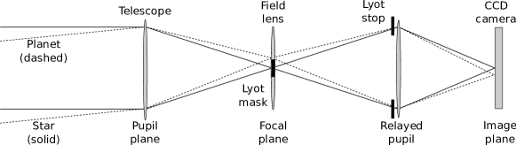
In a traditional coronagraph device (cfr. Fig. 1), the light of a star and its companion is focused by the telescope in the focal plane, where an opaque mask is placed. This element, called “Lyot Mask”, has a typical size designed to mask the light of the star without masking the light of the near planet. A lens in the focal plane provides the re-imaging of the field in a relayed pupil plane. Here, the residual light of the star is diffracted into a bright ring. An annular opaque mask, called “Lyot stop”, masks this light improving the nulling of the star. Finally, a convergent lens re-images the field in its focal plane, where the detector (for example a CCD camera) is placed.
In our implementation (cfr. Fig. 2), the opaque mask is replaced by a flat mirror with a central hole, so that the central part of the beam, i.e. the light of the star, is not absorbed but it is recuperated. It is referred to the “reference beam”. The residual light of the star’s Airy peak, which does not pass through the hole, is referred to the “direct beam”, and proceeds its path together with the light of the planet. The reference beam is deflected in such a way that it intersects the direct beam in the pupil plane, where the Lyot stop is placed.
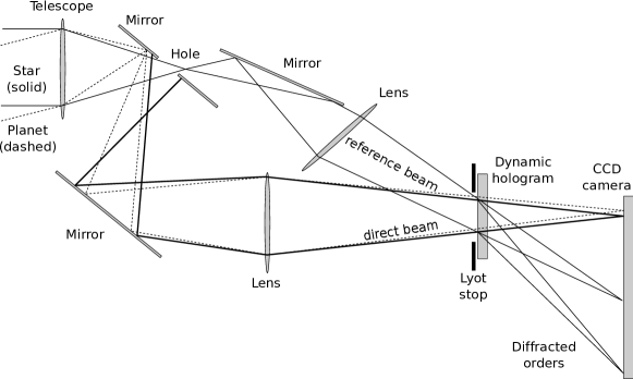
A dynamic hologram is located just behind the Lyot stop, and its functioning is basically summarized as follows:
-
•
The reference beam and the direct beam add in a coherent way, creating fringes in the speckles of the hologram. This process is called “recording the hologram”. The fringes of the recorded hologram act like a grating, diffracting several orders which become focused in the focal plane.
-
•
by illuminating the recorded hologram with the reference beam only, a reconstructed image of the star’s speckles appears on the detector, together with other diffracted orders. Using a reference beam phase-shifted by or a negative hologram, we obtain the same image phase-shifted by .
-
•
Our technique consists in creating an interference between the direct beam and the phase-shifted of the order +1 of the reference beam. Thanks to this phase shifting, the order 0 of the direct beam adds destructively with the reconstructed image of the star’s speckle, thus nulling the residual speckles of the star.
-
•
The planet’s light, being incoherent with respect to the reference beam is not reconstructed by the hologram, and not erased in the focal plane.
In a more performing design, the hole in the flat mirror can be replaced by a micro-prism. This approach is presented in our recent paper[1], while here we have presented a simpler concept.
3 Numerical simulations
First, we have re-computed a large number of simulations presented in our paper in order to display graphics with error bars: we simulated a space telescope (analogue to the James Webb Space Telescope, hereafter JWST), equipped with our coronagraphic system, and we imagined the telescope observing an analogue of the Sun-Earth system at from us. From that position, the angular separation between the star and the Earth-like planet would be such that the planet would lie on the fifth ring of the Airy pattern created by his parent star.
In our setup we maintained the optimizations already determined[1], and we tested the performances under different conditions. Each simulation was calculated under the assumption of mirror bumpiness of and .


-
•
Simulations without photon noise. Several kinds of coronagraphs were simulated: a classical Lyot coronagraph; a Lyot coronagraph with apodized pupil; an apodized coronagraph provided with hologram; and finally an apodized coronagraph provided with hologram and with the analytical subtraction of the twin wave (see our recent work[1] for more explanation about the twin wave). Under these conditions, the magnitude of the star is indifferent, as the absence of photon noise does not degrade the signal-to-noise ratio. The results are shown in Fig. 3.
Under such condition we are able to increase the performances by a factor (at ) and (at ) with respect to the apodized coronagraph. -
•
Simulations adding photon noise both on the final image (CCD) and on the hologram. We concentrated on the differences between our most performing coronagraph (apodized, provided with hologram and without twin wave) and its analogue without hologram (the apodized coronagraph). In this situation it is possible to test the limits of validity of our instrument as a function of the magnitude of the star. The results are shown in Fig. 4.
When the star is bright enough, we reach the maximum nulling power achievable with an hologram: this happens at magnitude (at ) and (at ), and improves the detection limit by a factor and respectively. When the star is too faint, the performances are not better than those of the apodized coronagraph: this happens at magnitude (at ) and (at ). -
•
Simulations adding transmission noise on the hologram. We simulated several levels of random transmission noises to create these transmission errors on the hologram pixels. The results are shown in Fig. 5.
The effect of this kind of noise is numerically approximately equivalent to the photon noise treated above (even if it is not the same phenomenon), and once again we show the limits of validity of our instrument, by varying the amount of the transmission noise: when this noise is less than of the value of the hologram pixels (at ) and (at ), the performances are not degraded. If the transmission noise is more than of the value of the hologram pixels (at ) and (at ), the performances match those of the apodized coronagraph.
Several sets of measurements were performed, in order to obtain different realizations of noise and calculate for the error (rms of the mean of the values at the level).
We performed a preliminary laboratory test using a static 2-layer hologram (a photo-polymerizable layer and a liquid crystal polymer layer). The results are encouraging but further tests are required.
4 Conclusions
Our simulations show that it is possible to override the current limits of coronagraphic systems by adding, in the optical scheme, a dynamic hologram able to remove the residual speckle starlight.
The tests presented in this paper indicate that, in the framework of a practical implementation, it is sufficient to control the “actuators” of the hologram with a precision better than – in order not to be limited by the transmission noise. This allows to improve the performances of the coronagraph by a factor 1 000–10 000, and make this technique suitable for being developed and successfully applied to the next generation of space telescopes.
In the near furure, we will experiment such a coronagraphic hologram on a laboratory test bench.
References
- [1] Ricci, D., Le Coroller, H., and Labeyrie, A., “Extreme coronagraphy with an adaptive hologram. Simulations of exo-planet imaging,” A&A 503, 301–308 (Aug. 2009).
- [2] Serabyn, E., Mawet, D., and Burruss, R., “An image of an exoplanet separated by two diffraction beamwidths from a star,” Nature 464, 1018–1020 (Apr. 2010).
- [3] Lyot, B., “The study of the solar corona and prominences without eclipses (George Darwin Lecture, 1939),” MNRAS 99, 580–+ (jun 1939).
- [4] Riaud, P., Boccaletti, A., Baudrand, J., and Rouan, D., “The Four-Quadrant Phase Mask Coronagraph. III. Laboratory Performance,” PASP 115, 712–719 (jun 2003).
- [5] Roddier, F. and Roddier, C., “Stellar Coronograph with Phase Mask,” PASP 109, 815–820 (jul 1997).
- [6] Riaud, P., Boccaletti, A., Rouan, D., Lemarquis, F., and Labeyrie, A., “The Four-Quadrant Phase-Mask Coronagraph. II. Simulations,” PASP 113, 1145–1154 (sep 2001).
- [7] Guyon, O., “Phase-induced amplitude apodization of telescope pupils for extrasolar terrestrial planet imaging,” A&A 404, 379–387 (jun 2003).
- [8] Labeyrie, A., “Removal of coronagraphy residues with an adaptive hologram for imaging exo-Earths,” in [EAS Publications Series ], Aime, C. and Soummer, R., eds., EAS Publications Series 12, 3–10 (2004).