Channel-coded Collision Resolution by Exploiting Symbol Misalignment
Abstract
In random-access networks, such as the IEEE 802.11 network, different users may transmit their packets simultaneously, resulting in packet collisions. Traditionally, the collided packets are simply discarded. To improve performance, advanced signal processing techniques can be applied to extract the individual packets from the collided signals. Prior work of ours has shown that the symbol misalignment among the collided packets can be exploited to improve the likelihood of successfully extracting the individual packets. However, the failure rate is still unacceptably high. This paper investigates how channel coding can be used to reduce the failure rate. We propose and investigate a decoding scheme that incorporates the exploitation of the aforementioned symbol misalignment into the channel decoding process. This is a fine-grained integration at the symbol level. In particular, collision resolution and channel decoding are applied in an integrated manner. Simulation results indicate that our method outperforms other schemes, including the straightforward method in which collision resolution and channel coding are applied separately.
Index Terms:
collision resolution, interference cancellation, channel-coded MUDI Introduction
An important issue in wireless random-access networks is how to deal with the collisions caused by simultaneous packet transmissions. Multiuser detection (MUD), first proposed by Verdu in the 1980s, is the traditional method to solve this problem. However, this method relies heavily on the crosscorrelation of the signature waves, thus it is mainly used in CDMA channels.
In this paper, we are interested in resolving the collisions in 802.11-like wireless local area network (WLAN). By collision resolution, we mean extracting the individual signals within an overlapped signals in a collision. In carrier-sense multiple-access (CSMA) WLAN, the carrier-sensing mechanism tries to avoid simultaneous transmissions by different users. However, collisions can still happen when the backoff process of two or more stations count down to zero at the same time. Collisions can also happen due to the hidden-node problem [1, 2] wherein two stations that cannot carrier-sense each other transmit simultaneously.
The signature waves of different users are the same in a WLAN, making collision resolution particular challenging. However, in a WLAN, when the signals of simultaneously transmitting stations reach a receiver, their symbols will most likely not be aligned. This introduces a certain degree of orthogality between the same signature waveforms. In particular, this symbol misalignment can be exploited for the extraction of individual signals. In [5] we proposed an algorithm named CRESM (Collision Resolution by exploiting Symbol Misalignment) to do so. CRESM has the same performance as the traditional Asynchronous MUD (A-MUD) [3] when the signature waveforms of users are the same, but with smaller complexity.
Although CRESM and A-MUD can minimize the probability of error optimally [3, 6], the BER is still unacceptably high. In this paper, we investigate the use of channel coding on top of CRESM to reduce the error probability. Channel-coded MUD applied on different signature waves can be traced back to a decade ago, when Wang and Poor et al. [4] combined the idea of Turbo coding with MUD. This method is mainly targeted for the CDMA system. We shall refer to this method as Turbo-SIC (Turbo Soft Interference Cancellation).
An insight from CRESM [5] and traditional MUD [3] is that joint decoding of the symbols may yield better results in the non-channel-coded case. An outstanding issue is whether joint decoding will also yield better results in the channel-coded case. In particular, can we integrate channel decoding and the exploitation of the symbol misalignment under one framework?
In this paper we present a scheme, named C-CRESM (Channel-coded CRESM), for this purpose. To illustrate our method, we focus on the use of the Repeat Accumulate (RA) channel code [8]. By constructing a virtual Tanner graph associated with the misaligned collided bit streams, we derive the message update rules in the associate belief propagation algorithm to extract the collided signals. Simulation results show that C-CRESM can perform better than Turbo-SIC. The improvement is particularly significant when the target BER is below .
The remainder of this paper is organized as follows: Section II gives the system model. Section III presents C-CRESM. Section IV compares C-CRESM with other channel-coded MUD methods. Section V gives simulation results that demonstrate the superiority of C-CRESM over these other schemes. Section VI concludes this paper.
II System Model
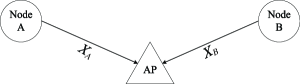
We consider the asynchronous multiple access channel with two end nodes (node A and node B) transmitting to one Access Point (AP), as shown in Fig. 1. Both end nodes employ BPSK modulation with the RA channel code, and the channel is assumed to be AWGN. Throughout this paper, we use capital letters to represent a packet. Specifically, , and denote the uncoded source packet, channel-coded packet, and received packet of node , respectively. The lowercase letters, , , and are the corresponding symbols in the packets, where and ( is the total length of the source packet and q is the repeat factor of RA code).
We represent a wireless packet by a stream of discrete complex numbers [11]. Specifically, we denote by complex numbers and the channel coded symbols of nodes A and B, respectively. The symbol duration is normalized to 1. The relative symbol misalignment between the collided signals is , where . The overlapped signals received at the AP can be expressed as follows
| (1) |
where is additive white Gaussian noise with power spectral density ; and are complex numbers representing the channel gains from A and B to the AP, respectively; is the largest integer no larger than ; is the carrier angular frequency.
We assume the channel is slow fading so that and stay constant within a packet duration, i.e., and . To ease exposition, we further assume that the transmit powers and the channel gains of the two nodes are the same, i.e., . We also assume perfect carrier phase synchronization. Note that this assumption is not absolutely needed, and we only use it to simplify the model for easier explanation. Simulation result in [5] shows that without carrier phase synchronization we can still decode the collision, albeit with a small SNR penalty.
We use the same digitalization method as in Fig. 3 of [5] we perform the matched filtering on the overlapped packet in every and periods alternatively, with a normalization factor and respectively. After oversampling the received signal we get two parts: the odd part, which is sampled over a duration of within a symbol, and the even part, which is sampled over the rest of the within a symbol. The sampled signals are as follows:
| (2) |
where , , and is a zero mean Gaussian noise with variance and respectively.
The above set-up is without channel coding. To incorporate channel coding, we consider the use of the RA channel code . We also focus on two-packet collisions in this paper. C-CRESM can be easily extended to deal with collisions with more than two packets.
III C-CRESM
In this section, we construct C-CRESM based on RA (repeat accumulate) code. This section is organized as follows: First we give a brief review of the RA code with its decoding algorithm. Interested readers who wish to learn more about RA code are referred to [7] for details. Then we construct a virtual Tanner graph, that reveals our C-CRESM can integrate channel coding with collision resolution. Finally, the message update rules of the associate belief propagation algorithm are derived to compute the source information of both nodes, based on the virtual Tanner graph.
III-A Review of RA code
The RA code can be decoded by applying the Belief Propagation (BP) algorithm [8]. The encoding (decoding) Tanner graph [9] is shown in Fig. 2 for a standard RA code. Generally speaking, the encoding process is like this (from left to right in Fig. 2): the source information is first repeated times ( in 2); then an interleaver is applied to de-correlate the adjacent repeated bits; finally the punctured bits are accumulated by an XOR operation (represented by nodes ) sequentially to get the channel coded bits (nodes ) for transmission.
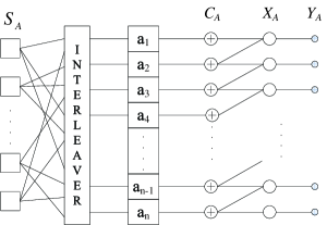
The decoding process applies BP on the Tanner graph. The observations are given. Based on that, first the channel coded bits are estimated. Message update rules of BP are then used to estimate the source information .The source information estimated in this first round are then used to refine the estimation . The right-to-left and left-to-right estimations are iterated until the estimated converges.
III-B Virtual Tanner Graph for RA coded CRESM
As with CRESM [5], we construct a virtual Tanner graph for resolving two-user channel-coded collisions under symbol misalignment. The difference with CRESM is that the transmitted data are channel-coded here but not in CRESM.
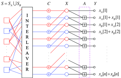
The collided symbols, after the application of the same oversampling and digitalization method as in [5], are , where and represent the repeated channel coded bits of the two end nodes. This representation ignores the noise terms that will be added back in our later discussion of the decoding process. The oversampled signals can be considered as the outputs of the virtual Tanner graph shown in Fig. 3. Note that in Fig. 3, the “square” add nodes (nodes A) are introduced to model the addition of collided signals when they arrive at the receiver simultaneously. There are actually no add nodes in the physical RA coders at the two transmitters. But together, the two RA coders appear to the receiver as a virtual coder that implements the code design corresponding to the virtual Tanner graph.
Based on the virtual Tanner graph in Fig. 3, we now discuss the decoding algorithm. It should be noted that although we assume BPSK modulation for simplicity, this algorithm can be generalized to other modulation schemes. We rewrite the oversampled signals in (2) as follows:
| (3) |
where is the i-th over-sampled symbol received minus the noise, and is the unmodulated mixture of signals from nodes A and B that corresponds to the i-th evidence node in the virtual Tanner graph.
III-C Definitions
Before discussing the decoding algorithm, let us first define some notations and terms. Define nodes S, C, X, A and Y to be the sets of source nodes, check nodes, code nodes, add nodes and evidence nodes, respectively. We refer to the line connecting any two nodes as an ‘edge’. Define to be the message from the k-th evidence node (a node in Y) to the k-th add node (a node in A), where and . We represent a message on a non-rightmost edge (i.e., an edge that is not between a node in A and a node in Y) by , , or .
is a probability vector, where . , and are also probability vectors, where , and are . Note that if k is odd, and if k is even.
III-D Message Update Rules
All messages associated with the non-rightmost edges in Fig. 3 are initially set to (1/2, 1/2). is computed based on the received signals and will not change throughout the iteration. and for are given as follows:
| (4) |
where is a normalized factor given by .
| (5) |
where is a normalized factor given by .
Without loss of generality, we omit the time index k for simplicity in the following discussion of message-update rules. We follow the principles and assumptions of the BP algorithm to derive the update equations, i.e., the output of a node should be consistent with the inputs while adopting a ’sum of product’ format of the possible input combinations [13].
Based on the above and the initial values of all other messages, the right-to-left messages in the Tanner graph are first updated (III-D1 to III-D3 below). After that, the left-to-right messages are updated (III-D4 to III-D6 below). The above updates are iterated until the message values converge. The procedure is similar to that in [10, 8] except for the modifications required to deal with the virtual add nodes A in Fig. 3.
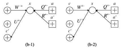
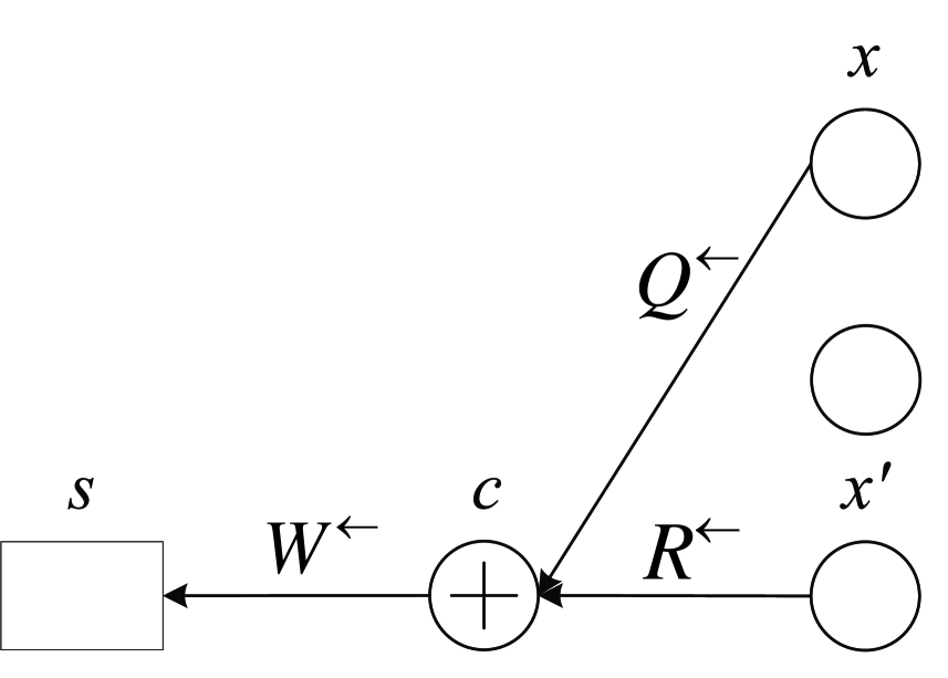
III-D1 From add nodes to code nodes
With reference to Fig. 4, we derive the update equations for a right-to-left message from an add node to a code node. The update is based on the existing value of the left-to-right message and the fixed message from the evidence node.
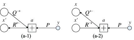
The symbol can only be 0 if or (i.e., for compatibility, must be ). Based on the sum-product principle of the BP algorithm, we have
| (6) |
Similarly, we have
| (7) |
Thus, the overall message update associated with the compatibility requirement of an add node is given by
| (8) |
Similarly, with reference to Fig. 4(a-2), we can obtain the update equation for message in the direction of to :
| (9) |
Note that in BP, the two messages in opposing directions on the same edge are distinct. In particular, the input values of in (8)and in (9) are the values obtained from the prior iteration for the messages in the ‘’ direction. For example, the used in (9) are NOT those obtained from (8), but those obtained from the prior iteration for a message from to .
We note from the virtual Tanner Graph in Fig. 3 that there is no add node in the top row. Thus, the message going into the node is simply set to (note: always).
III-D2 From code nodes to check nodes
With reference to Fig. 5(b-1), we now derive the update equations for the message from a code node to a check node. As shown in the figure, the three input messages are , and . Based on the compatible sum-product principle of the BP algorithm, we have
| (10) |
where is a normalization factor to ensure that the sum of probabilities, . Similarly,
| (11) |
So the overall message update associate with the compatibility requirement of a code node is given by
| (12) |
Similarly, with reference to Fig. 5(b-2), we can obtain the update equation for message :
| (13) |
III-D3 From check nodes to source nodes
With reference to Fig. 7, we now derive the update equations for the message from a check node to a source node. The symbol s can only be 0 if or (i.e., for compatibility, must be s). Based on the sum-product principle of the BP algorithm, we have
| (14) |
Correspondingly can be obtained in a similar way. So we have the messages going out from the check node:
| (15) |
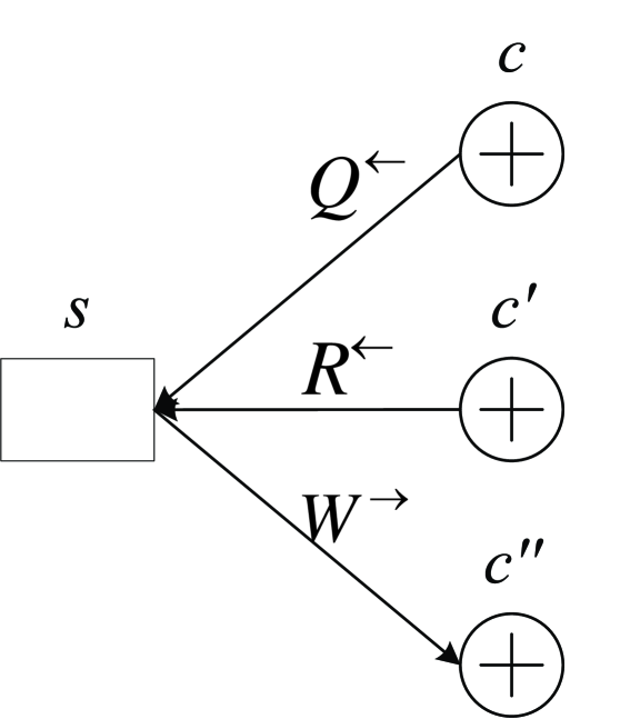
III-D4 From source nodes to check nodes
We now proceed to the updates of messages flowing from left to right. With reference to Fig. 7, we derive the message update rules for the message from a source node to a check node. Again, based on the compatible sum-product principle of BP, we have
| (16) |
where is a normalization factor to ensure . So we have the output message of the source node as follows:
| (17) |
Similarly we have
| (18) |
| (19) |
III-D5 From check nodes to code nodes
The update equations for the message from a check node to a code node are similar to those from a check to a source node in Part 3), except for the update direction. So we omit the details here.
III-D6 From code nodes to add nodes
The update equations for the message from a code node to an add node are similar to those from a code to a check node in Part 2), except for the update direction. So we also omit the details here.
After the above parts are iterated and the values of the messages converge, we declare that , where , , and are obtained from the three messages , and flowing into the source node.
IV Comparison of Different Methods
We consider three channel-coded collisions resolution methods, classified by how symbol misalignment is exploited in the channel-decoding process. The first method performs the channel decoding after the application of CRESM or A-MUD on the collided signal. Thus, the channel decoding and collision resolution process are decoupled. The second method is to apply Turbo-SIC to iteratively decode the collided packets by applying a BP algorithm, which is done in packet level. The third method is C-CRESM. As presented in the preceding section, C-CRESM jointly decodes the channel-coded misaligned signals at the symbol level.
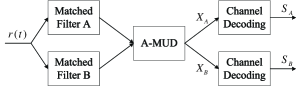
IV-A Independent Multiuser Detection and Channel Decoding (Independent MU-CD)
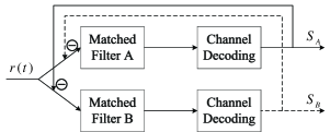
The structure of the decoding process is shown in Fig. 8. First the receive signals are passed through two matched filters; then A-MUD is applied on the MF outputs to get the channel coded packets; finally the channel coded symbols are decoded by standard channel decoding. It could be understood intuitively that separating the collision resolution and channel-decoding processes may not be optimal. The channel-coded bits are dependent on each other, but CRESM or A-MUD does not exploit this property in the collision resolution process. This method, however, is simple.
IV-B Turbo-SIC
Turbo-SIC was proposed in [4] to decode channel-coded packets in a CDMA system. The structure of the decoding process is shown in Fig. 9. Turbo-SIC digitalizes the signals by matched filtering, and thus relies heavily on the crosscorrelation of signature waves. In the CDMA system, the signature waves of different users are different (i.e., the matched filters A and B in Fig. 9 correspond to near-orthogonal signature waves). In the system of interest to us here, the signature waves are the same except for the symbol misalignment. The system will certainly not perform well when the symbol misalignment is zero. For non-zero symbol misalignment, the performance will improve.
With reference to Fig. 9 again, the structure of the decoding process is under the framework of successive interference cancellation (SIC) [12, 14]. The channel decoding is performed for each signal separately after matched filtering. The soft information of the separately decoded signals are then fed back to the front end for interference cancellation purposes. The process of matched filtering, channel decoding, and interference cancellation is iterated to reduce the error probability progressively. Within each iteration, the symbols from different branches of the decoder do not “interact”. So, this method is a packet-level joint MUD channel decoding.
IV-C Channel-coded CRESM (C-CRESM)
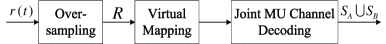
Symbol misalignment of collided signals result in a “virtual signal” with “virtual symbols” at twice the rate of the original symbols from each source, after being oversampled. These virtual symbols are correlated in two ways. First, adjacent virtual symbols are correlated via misalignment of original symbols. Second, they are correlated via the channel coding. The idea of C-CRESM is to make use of these correlations to better decode the underlying symbols embedded in the virtual symbols. In this paper, we assume the use of RA channel code. C-CRESM maps the virtual symbols to evidence nodes in the virtual Tanner graph shown in Fig. 10 and Fig. 3. It then uses BP to decode the underlying symbols.
V Simulation Results
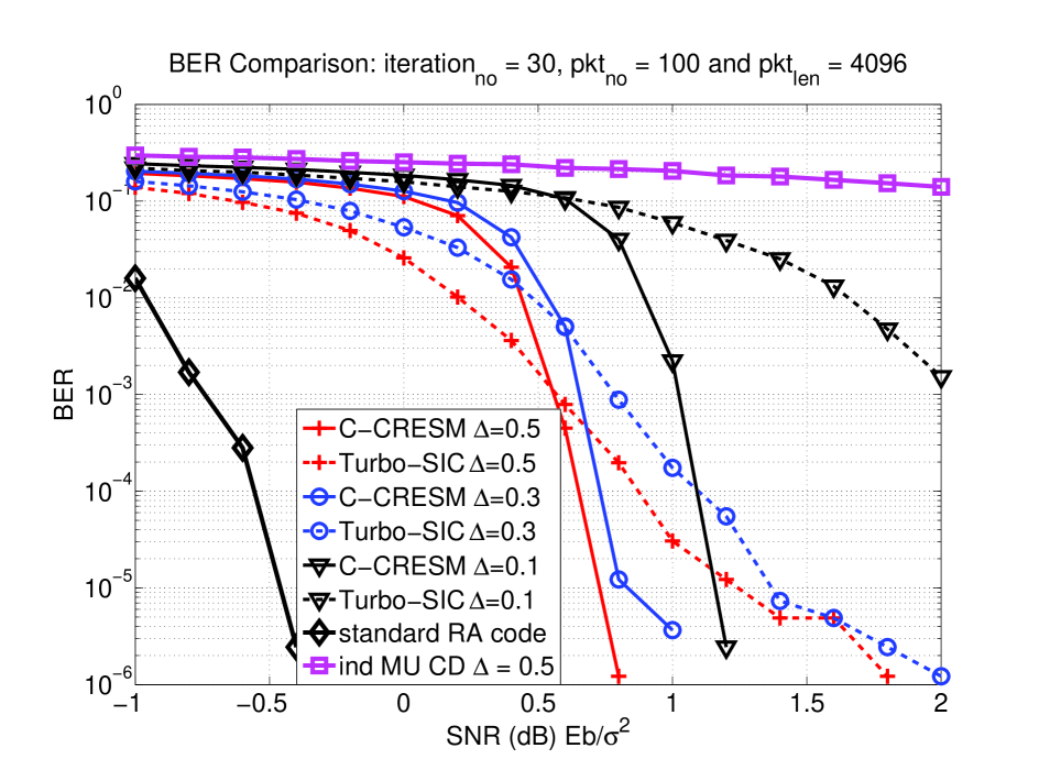
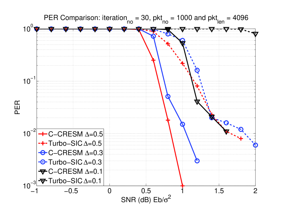
In this section we present simulation results to illustrate the performance of C-CRESM compared with Turbo-SIC (the Turbo-SIC method outperforms the traditional separate channel decoding and MUD method, which is represented by the magenta line with square markers on it in Fig. 13.). In all the simulations, we assume BPSK modulation with phase synchronization. The repeat factor for the RA code is with an interleaver that is randomly selected for each packet but identical for C-CRESM and Turbo-SIC. Note that here we only consider the average results of different interleavers, but in practice we should fix the system to a good interleaver. The choice of an interleaver is beyond the scope of this paper, however. We refer the reader to [8] for details.
We assume the noise is AWGN with variance and define the SNR as (i.e., the signals from both ends have unit power.). For our simulations, we modify Turbo-SIC in [4] to also use the RA code for fair comparison with C-CRESM. The Turbo iteration number (the outer loop in Fig. 9) is and the RA decoding iteration number is (the iteration within the channel decoding block in Fig. 9). Thus, the total number of iterations in Turbo-SIC is . We also set the iteration number in C-CRESM to be for fair comparison. The computation costs within each iteration of the schemes are the same, which can be easily derived from the message update rules and message set.
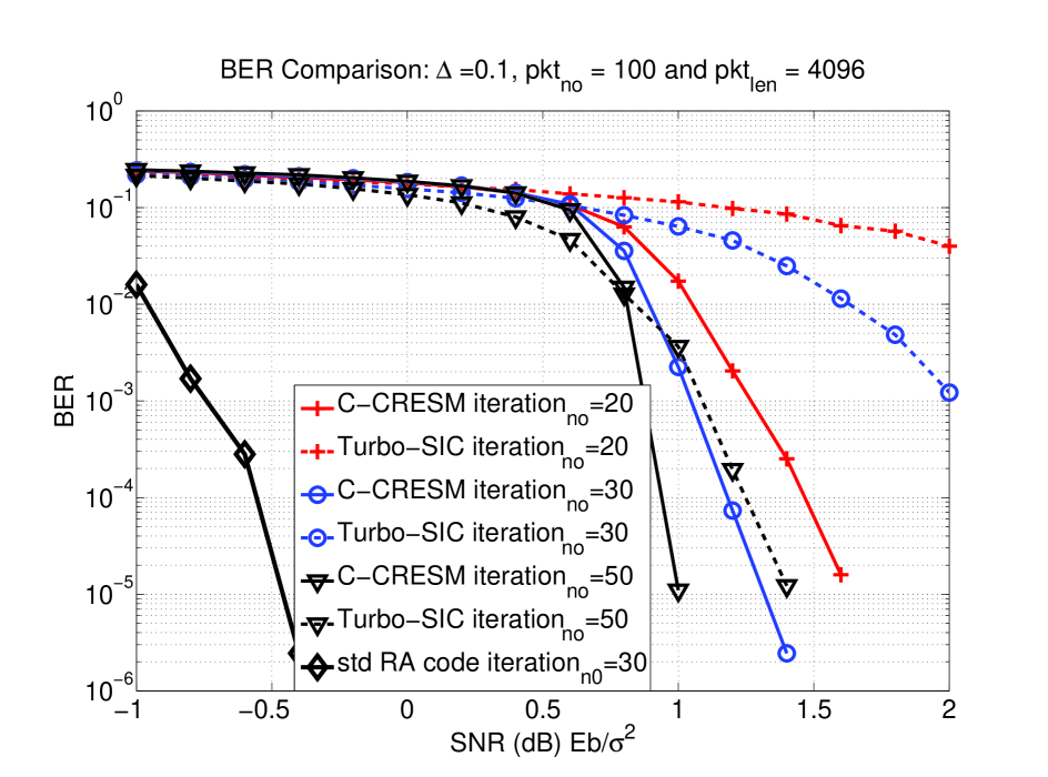
The black line with a ‘diamond’ marker in Fig. 13 and Fig. 13 is the standard one to one RA code communication result, served as a benchmark for comparison. Fig. 13 shows for the target BER below , C-CRESM performs better than Turbo-SIC by 0.25 to 1.5 dB for different . Fig. 13 compares C-CRESM with Turbo-SIC for different iteration numbers, fixing . For both schemes, the performance improves as iteration number increases, and C-CRESM has a 0.3 to 1 dB improvement at the BER of . Both figures reveal that as SNR increases, the SNR-BER curve of C-CRESM drops faster than that of Turbo-SIC. Fig. 13 presents the packet error rate (PER) for various . Again, C-CRESM performs better than Turbo-SIC by at least 0.75 dB for target PER below . For both BER and PER, the advantage of C-CRESM over Turbo-SIC is particularly striking when . Since C-CRESM can work effectively over a wider range or , it is robust when deployed in the field, where there is no deliberate synchronization to control .
VI Conclusion
This paper has proposed and investigated C-CRESM, a novel channel-coded collision resolution method, targeting at 802.11-like WLANs. This method integrates the collision resolution process and the channel decoding process into one mechanism. A key ingredient in this method is the observation that symbols of collided signals in a WLAN are most likely not aligned when they arrive at the receiver. This is because there is no deliberate attempt to synchronize the transmitters at the symbol level. It turns out that such symbol misalignment is good because it introduces a certain degree of orthogonality between the otherwise similar signal waveforms of the collided signals.
C-CRESM exploits the symbol misalignment in the channel decoding process. In particular, we show that when the RA channel code is used, the collided signals at the receiver (from multiple sources) can be thought of as a virtual signal (from single source). The virtual signal corresponds to a virtual RA channel code, which is a superposition of the overlapped, misaligned, RA codewords in a collision. This concept allows us to construct a virtual Tanner graph for an integrated collision-resolution-and-channel-decoding process.
The integrated decoding process in C-CRESM operates at the symbol level. Our simulation results show that it outperforms the straightforward method in which collision resolution and channel decoding are performed in an independent way, as well as the method in which collision resolution and channel decoding are integrated at the packet level (Turbo-SIC). Compared with independent collision resolution and channel decoding, C-CRESM have a more than 3dB gain. Compared with Turbo-SIC, C-CRESM has more than 0.75dB gain when the target PER is for typical packet lengths. C-CRESM is also more robust against the variation of the symbol misalignment compared with these other methods.
References
- [1] P.C. Ng, S.C. Liew, K.C. Sha, and W.T. To, “Experimental Study of Hidden Node Problem in IEEE 802.11 Wireless Networks,” in Proc. IEEE SIGCOMM 2005, Philadelphia, PA, Aug. 2005.
- [2] L. B. Jiang and S. C. Liew, “Hidden-node Removal and Its Application in Cellular WiFi Networks,” IEEE Trans. on Vehicular Technology, vol. 56, no. 5, pp. 2641-2654, Sep 2007.
- [3] S. Verdu, “Minimum Probability of Error for Asynchronous Gaussian Multiple-Access Channels,” IEEE Transactions on Information Theory, vol. IT-32, no. 1, pp. 85-96, Jan. 1986.
- [4] X. Wang and V. Poor, “Iterative (Turbo) Soft Interference Cancellation and Decoding for Coded CDMA,” IEEE Transactions on Communication, vol. 7, No. 7, July 1999.
- [5] L. Lu, S. C. Liew and S. Zhang, “Collision Resolution by Exploiting Symbol Misalignment,” to be submitted. A primary online version: http://arxiv.org/ftp/arxiv/papers/0810/0810.0326.pdf
- [6] S. Verdu, Multiuser Detection, Cambridge University Press, 1998.
- [7] D. Divsalar, H. Jin, and R. J. McEliece, “Coding theorems for Turbolike codes,” in Proc. 36th Allerton, Allerton, Illinois, pp. 201-210, Sept. 1998.
- [8] H. Jin, “Analysis and design of Turbo like code,” Ph.D Thesis of California Institute of Technology, May 2001.
- [9] F. R. Kschischang, B. J. Frey, H.-A. Loeliger, “Factor graphs and the sum-product algorithm,” IEEE Trans. on Inform. Theory, vol. 47, no. 2, Feb. 2001.
- [10] S. Zhang and S. C. Liew, “Joint Design of Physical-Layer Network Coding and Channel Coding,” to appear on IEEE JSAC.
- [11] B. Sklar, Digital Communications: Fundamentals and Applications (second editon) Prentice-Hall PTR, 2001.
- [12] D. Halperin, T. Anderson, and D. Wetherall, “Taking the String out of Carrier Sense: Interference Cancellation for Wireless LANs,” ACM MOBICOM 2008, San Francisco, USA.
- [13] J.S. Yedidia, W.T. Freeman, and Y. Weiss, “Understanding belief propagation and its generalizations,” Technical Report TR2001-22, MERL, 2001.
- [14] D. Tse and P. Viswanath, Fundamentals of Wireless Communication, Cambridge University Press, 2005