Rotational tuning of interaction in metamaterials
Abstract
We experimentally observe the tuning of metamaterials through the relative rotation of the elements about their common axis. In contrast to previous results we observe a crossing of resonances, where the symmetric and anti-symmetric modes become degenerate. We associate this effect with an interplay between the magnetic and electric near-field interactions and verify this by calculations based on the interaction energy between resonators.
Metamaterials created as an array of sub-wavelength, resonant elements can exhibit interesting electromagnetic properties, such as a negative refractive index Smith et al. (2000). Unlike the atoms in natural materials, the near-field patterns of metamaterial elements are quite complex, giving rise to strong interactions between them. Understanding this interaction is essential as it determines the overall resonant properties and effective parameters of the material. By controlling the relative arrangement of elements, it is possible to change this coupling and tune the properties of the structure Liu et al. (2009); Lapine et al. (2009); Powell et al. (2009). This allows us to alter the response of the material substantially without having to greatly alter the geometry or constituents.
An important building block of metamaterials is the Split Ring Resonator (SRR) Pendry et al. (1999), which can exhibit a negative magnetic response due to its strongly resonant magnetic polarizability. By coupling a pair of SRRs, chiral properties Liu et al. (2007) and trapped dark modesLi et al. (2009) can also be observed. In this Letter, we study the dynamics of two microwave SRRs broadside coupled to each other, varying twist angle between them, as shown in Fig. 1(a). A similar system operating at near infra-red frequencies was presented in Ref. Liu et al., 2009, however in this work we show a substantially different regime of interaction verified experimentally for microwaves.
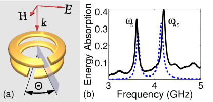
The rings used have an inner radius of 3.5mm, an outer radius of 4mm, and a gap of 1mm. They are copper, printed onto 1.6mm thick FR4 circuit board, and the rings are 3.6mm apart, with the dielectric boards located between the rings. The incoming microwaves are polarized so that the electric field is in the direction, as shown in Fig. 1(a). Numerical calculations were performed using CST Microwave Studio with the boards having a dielectric constant of 4.6.
The most meaningful definition of the resonant frequency is the frequency of maximum excitation of currents within the rings. This can be determined most readily by considering the absorption of the system, given by , where is the transmission coefficient, and is the reflection coefficient. A comparison of the experimental and numerical curves for is shown in Fig. 1(b).
Experimental results were measured using a Rohde and Schwarz ZVB network analyzer in a WR-229 rectangular waveguide, with varied from to in increments, while numerical results were calculated in increments. The resonant frequency for each angle was found from the maximum of the absorption curve, and the resulting numerical and experimental results are compared in Fig. 2.
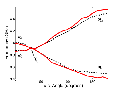
For , there are two resonances and , and by inspection of the currents in the rings we verify that these correspond to the expected symmetric and anti-symmetric modes. As increases, increases and decreases, reaching their maximum and minimum values respectively at . For our chosen parameters the resonances cross at , in contrast to Ref. Liu et al., 2009, where an avoided crossing of resonances was found which was attributed to the electric quadrupole and octupole moments of the rings.
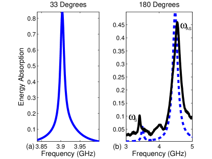
The numerical absorption curve at is shown in Fig. 3(a). This curve was calculated assuming loss free dielectric boards, so as to ensure the position of the crossing, given the low coupling of the asymmetric mode close to . It is quite clear here that there is only one resonance to be observed.
As can be seen in Fig. 3(b), the two resonances have different Q factors (widths), which can be attributed to conduction and radiation losses. The suppression of radiation losses in the symmetric mode is related to the magnetic and electric dipole arrangementsLi et al. (2009), where the electric dipole has much stronger radiation losses. The asymmetric mode has mostly an electric dipole response, causing greater radiation losses, whereas the radiation losses at the symmetric mode have been suppressed by a dominating magnetic dipole. The radiation distribution then changes with angle , as can be seen by comparing Figs. 1(b) and 3(b).
The tuning of the system by rotation can be explained by looking at the interaction between the rings. As the rings are twisted, the magnetic and electric near-fields of the two rings change, changing the coupling between the resonances. This is approached theoretically using the Lagrangian for a pair of coupled SRRs Powell et al. (2009):
| (1) |
where and are the dimensionless magnetic and electric interaction constants and is the time-dependent mode amplitude. By substituting Eq. (1) into the Euler-Lagrange equation we find that
| (2) | |||
| (3) |
This then allows the two resonances to be found - symmetric (when ), and asymmetric (when ):
| (4) |
In principle if is known, then by inverting Eq. (4) it is possible to fit and from and . However we found that this procedure is extremely sensitive to error and does not yield usable results. Instead, we start from the approach outlined in Ref. Powell et al., 2009 to evaluate the interaction energy between the fundamental modes of the rings.
For a pair of rings in a homogeneous dielectric background, the interaction constants are shown in Fig. 4(a). We find that the interaction constants are very well described by and with , and . These constants are dictated by the charge separation across the gap of the ring, the current circulating around the ring, and the inhomogeneity of the current distribution around the ring, respectively. For rings aligned on the same axis, we expect that the magnetic interaction should always be positive, as the intersecting magnetic field from one loop should always be normal to the other loop. In addition the electric interaction should be positive at as the charge distribution has the nature of parallel dipoles. All arrangement of rings on the same axis which we considered obeyed these considerations.
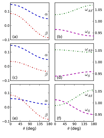
In Fig. 4(b) we plot the corresponding frequencies of the symmetric and anti-symmetric modes, normalized to . As our approach models the response of the resonators in a homogeneous dielectric background, the results are significantly different from those observed experimentally, where the dielectric is inhomogeneous and the effect of waveguide boundaries is also significant. In particular, the crossing of resonances cannot be reproduced for rings in homogeneous background. Therefore we consider the possible regimes of interaction which may occur, under the assumption that the interaction constants can be fitted as described above.
The case considered in Fig. 4(a-b) corresponds to the magnetic interaction always being larger than the electric interaction. This results in increasing splitting of and with increasing twist angle, however in principle there is no reason why the splitting cannot decrease. We show such a case in Fig. 4(c-d), where we have set , such that the inhomogeneity in the current has a stronger influence than the dipole-like charge distribution. Despite the apparent difference in frequency splitting curves, there is little difference between the interaction constants shown in Fig. 4(a) and (c).
The only other case allowed in our model of interaction under the afore-mentioned physical constraints on and is that for . An example of this is given in Fig. 4(e), where we have reduced the magnetic coupling such that at some angle , by setting . The corresponding resonant frequencies normalized to are plotted in Fig. 4(f). We see that for low twist angle, occurs at a higher frequency, but decreases with angle and crosses . Clearly this regime corresponds to what we observe in experiment, and we hypothesize that the inhomogeneous dielectric serves to enhance the electric interaction relative to the magnetic interaction in our system.
In Ref. Liu et al., 2009 it was claimed that the resonances converge, undergo an avoided crossing, then diverge, as increases. Utilizing both our analytical model and full numerical simulation, we could not find this regime in our system. We also note that for our structure the assumption of constant magnetic interaction with twist angle is not justified. However by taking the inhomogeneity of magnetic interaction into account, we find that we can neglect higher order electric interactions.
Equations (4) show that the tuning curves arise from competition between electric and magnetic interaction constants. This means that even when interaction is strong, the corresponding frequency splitting can still be weak. The experimentally-observed crossing angle represents a particularly interesting case, and it occurs when . In the lossless case the symmetric and anti-symmetric resonances become degenerate, and although both electric and magnetic interaction coefficients are strong, they effectively cancel each other out. However in the presence of losses, we need to consider the eigenfrequencies and as complex values, with imaginary parts corresponding to the losses. By examining Fig. 3(b) we see that the coupling of the modes to the waveguide is not identical, hence they have different radiation losses. Thus it becomes very unlikely that in the complex plane for any parameter value, and true degeneracy does not occur. Therefore it is not possible to cancel out the interaction between rings, and our numerical work verified this.
In conclusion, we have shown that by changing the relative rotation between two rings, we can significantly change the coupling, which causes the resonances to change. We have found that there is a crossing where the two resonances coexist, which corresponds to equal electric and magnetic coupling.
Acknowledgements.
We acknowledge funding from the Australian Research Council and useful discussions with Maxim Gorkunov and Andrey Miroshnichenko.References
- Smith et al. (2000) D. Smith, W. J. Padilla, D. Vier, S. Nemat-Nasser, and S. Schultz, Phys. Rev. Lett., 84, 4184 (2000).
- Liu et al. (2009) N. Liu, H. Liu, S. Zhu, and H. Giessen, Nat Photon, 3, 157 (2009).
- Lapine et al. (2009) M. Lapine, D. Powell, M. Gorkunov, I. Shadrivov, R. Marques, and Y. Kivshar, App. Phys. Lett., 95, 084105 (2009).
- Powell et al. (2009) D. A. Powell, M. Lapine, M. V. Gorkunov, I. V. Shadrivov, and Y. S. Kivshar, (2009), arXiv:0912.1152.
- Pendry et al. (1999) J. B Pendry, A. J Holden, D. J. Robbins and W. J. Stewart, IEEE Transactions on Microwave Theory and Techniques, 47, 2075 (1999).
- Liu et al. (2007) H. Liu, D. Genov, D. Wu, Y. Liu, Z. Liu, C. Sun, S. Zhu, and X. Zhang, Phys. Rev. B, 76, 073101 (2007).
- Li et al. (2009) T. Q. Li, H. Liu, T. Li, S. M. Wang, J. X. Cao, Z. H. Zhu, Z. G. Dong, S. N. Zhu, and X. Zhang, Phys. Rev. B, 80, 115113 (2009).