Tunneling limit of heavy-fermion point contacts
Abstract
We present results for a multichannel tunneling model that describes point-contact spectra between a metallic tip and a superconducting heavy-fermion system. We calculate tunneling spectra both in the normal and superconducting state. In point-contact and scanning tunneling spectroscopy many heavy-fermion materials, like CeCoIn5, exhibit an asymmetric differential conductance, , combined with a strongly suppressed Andreev reflection signal in the superconducting state. For Andreev reflection to occur a junction has to be in the highly transparent limit. Here we focus on the opposite limit, namely that of low transparency leading to BCS-like curves. We discuss the consequences of a multichannel tunneling model for CeCoIn5 assuming itinerant electron bands and localized electrons.
1 Introduction
Point contact spectroscopy (PCS) and scanning tunneling spectroscopy (STS) have been widely used to study the electronic properties of heavy-fermion superconductors (HFS). A general problem in this field has been the interpretation of tunneling data, which show asymmetric conductances in the normal state and significant deviations from the standard BTK formalism (Blonder-Tinkham-Klapwijk) [1]. In the past, the BTK formalism has been very successful in describing tunneling conductances between metal tips and conventional superconductors, while resulting in unphysical parameterizations of the HFS tunneling conductances.
Here we present results for a multichannel tunneling model between a metallic tip and a heavy-fermion superconductor. These results are discussed with respect to the anomalous properties observed in CeCoIn5 [2, 3, 4, 5, 6], but are readily applied to other heavy fermions (HF) like CeCu2Si2, URu2Si2 and many others [7, 8, 9, 10].
2 Tunneling model
We model the HF material by two itinerant bands and additional localized surface states, which may be caused by broken -electron bonds at the surface due to the broken translation symmetry,
| (1) |
The heavy-fermion Hamiltonian represents two bands of itinerant conduction electrons with band index and localized electrons near the surface with site index . The operators () create (destroy) an itinerant electron with momentum and spin in band , while operators () create (destroy) an electron at site with spin . are the respective electronic dispersions and is the energy level of the localized electrons.
A simple description of a tunneling experiment is comprised of Hamiltonians for the heavy-fermion material, the counter electrode, and the transfer or tunneling processes between them: . The counter electrode is given by normal conduction electrons
| (2) |
and the tunneling Hamiltonian describes all possible transfers
| (3) |
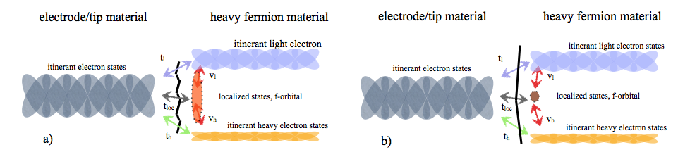
In addition to the standard overlap integrals between the conduction band in the point contact and itinerant heavy-fermion bands there is a finite overlap, , from the point contact to the localized states in the HF. We also account for weak coupling between the localized surface electrons and itinerant electrons through scattering terms (see Fig. 1). In general, to get a Fano resonance in the conductance one needs interference between different tunneling paths [11]. The resulting differential conductance calculated from this model will have an asymmetric Fano line shape. Figure 1 shows the processes that are active in tunneling between a metallic point contact and the HF material. Here we extend the picture of conduction through individual quantum channels to a tunneling model to account for point contacts on a HF material. When deriving the general tunneling expression, we consider strong overlap between electron states in the contact and the HF compound and thus go beyond the strict tunneling limit.
We calculate the tunneling current through a quantum channel by employing the standard non-equilibrium Green’s function technique [12, 13, 14, 15]. To further simplify our calculations, we make several assumptions: (1) The itinerant microscopic Green’s functions are described by quasiclassical Green’s functions near the Fermi energy. (2) It is essential to keep the full energy dependence of the localized Green’s function. We assume a single localized level at energy . (3) Only the heavy electrons undergo a superconducting transition at , while the light electrons remain uncondensed. For details of this model and formalism see Ref. [16].
3 Tunneling conductance
For a multiband tunneling model the differential conductance of a single quantum channel was derived in Ref. [16]. It leads to a generalized Fano expression for the conductance
| (4) |
In Eq. (4) is the transparency of the junction, is the tunneling-renormalized position of the localized energy relative to the Fermi level, is the half-width of the resonance, and with . The conventional Fano parameter controls the resonance shape. The additional parameter is present for multiband models only, when tunneling through a resonant localized state couples differently to the HF conduction bands (see below). The term adds a Lorentzian to the conventional Fano resonance.
For notational convenience, we introduce the following parameterization of the microscopic parameters and
| (5) |
where , are the effective tunneling elements with the density of states at the Fermi level in the heavy fermion (contact) material. The factor is the fraction of localized surface states and give the relative fraction of heavy and light electrons. The angles and give the relative overlap integrals between the direct tunneling and the hybridization matrix elements. For simplicity, we assume , which results in [16]. Finally, the angle quantifies the relative proportion of tunneling into a localized state relative to direct tunneling. The four non-zero phenomenological model parameters introduced in Eq. (4) now depend on the microscopic parameters and the three fractions .
3.1 Tunneling limit in the normal state
In the tunneling limit, , we keep the coupling term between localized and itinerant states at arbitrary strength and obtain
| (6) | |||||
| (7) | |||||
| (8) | |||||
| (9) |
Here is the itinerant fraction. It quantifies the relative weight of direct tunneling into light and heavy bands. The parameter is the effective hybridization matrix element at the surface, which is temperature independent.
In this limit the point-contact spectra measure a curve with a Fano line shape and allow us to directly relate the model parameters to the bulk state of the HF material. At temperatures low compared to the coherence temperature of the Kondo lattice, , the HF state can be described as a renormalized Fermi liquid [17, 18]. The density of state factors can be related to the ratio of the bare mass with the effective mass as and [17]. The temperature dependence of can be obtained, for example, from experiment. For qualitative purposes, we model it as , with . The factor describes the fraction of localized states and its physical meaning and value are under debate, see for example the discussion by Yang [19, 20].
We can gain some physical insight by considering three special scenarios on how the measured peak width of the Fano resonance
should depend on temperature if it was entirely due to the effective mass.
For simplicity, we keep only leading order tunneling terms and drop terms proportional to :
(1) The localized states or moments at the interface are not connected to the HF physics of the bulk. In this case, the fraction , giving the number of surface states, is temperature independent. We obtain
| (10) | |||||
| (11) |
where decreases with increasing temperature, while increases,
which is inconsistent with PCS measurements for CeCoIn5, see Ref. [16].
(2) Localized states or moments at the interface originating from the Ce 4f states at energy , which are the same as
in the bulk of CeCoIn5. In this case, it is reasonable to assume that
is proportional to the number of unscreened moments, i.e., . We obtain
| (12) | |||||
| (13) |
where both and increase with for . The increase
of is consistent with the PCS measurements, while that of is not
[16].
(3) The dominant temperature behavior of is caused by inelastic scattering processes like spin fluctuations. Resistivity experiments on CeCoIn5 show that may be described by a
self-consistent spin-fluctuation theory [21]. Similarly, spin-lattice relaxation rates
suggest the importance of spin fluctuations [22, 23, 24].
In a spin-fluctuation scenario the inelastic broadening
increases as , where , whereas to leading order
is temperature independent.
Therefore, broadening due to electrons scattering off spin fluctuations is a reasonable interpretation for the
temperature dependence of found in CeCoIn5 [16]
and more recently in URu2Si2 [9, 10].
We conclude that the self-consistent incorporation of inelastic scattering processes into our calculations,
similar to Ref. [25],
is an important next step to account for the observed line broadening.
3.2 Tunneling limit in the superconducting state
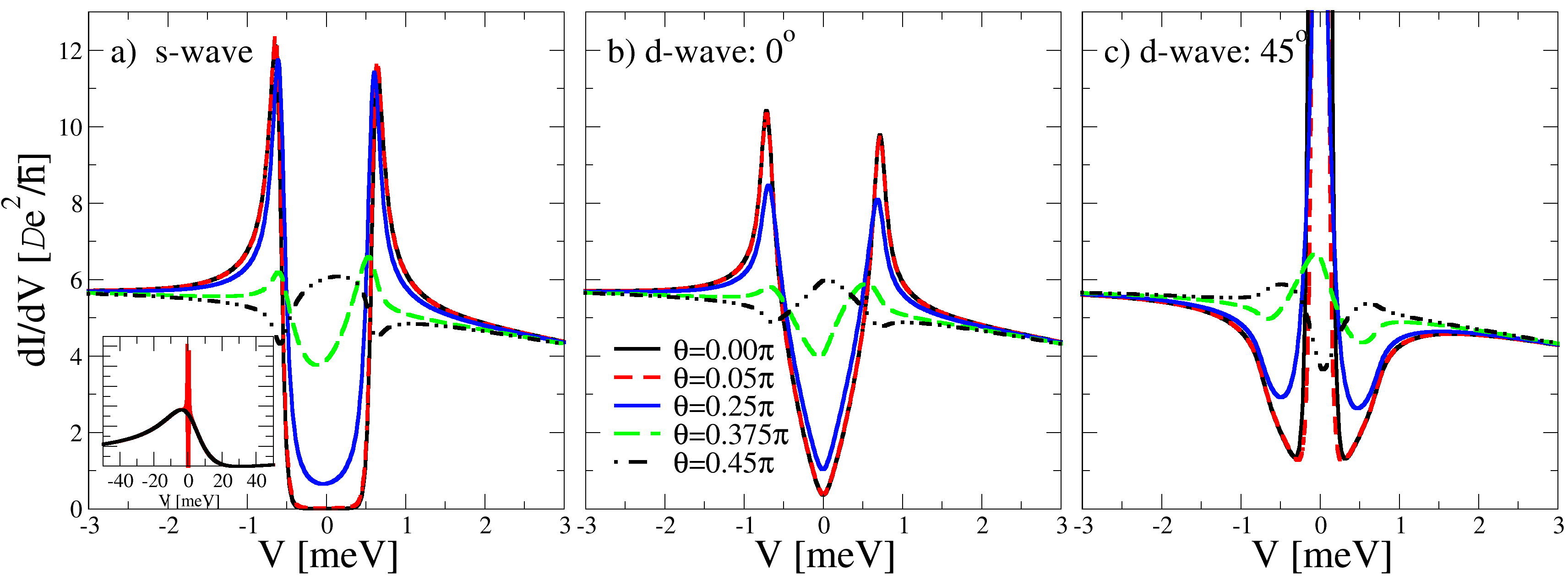
It is necessary to study tunneling in the superconducting state, where Andreev reflection processes modify the conductance, because one can extract additional information about the microscopic origin of the Fano conductance. The unknown relative ratio of tunneling into heavy or light bands can be determined as the depends in a non-linear way on . At very low temperatures, , one can assume that has saturated to its low- limit . Thus we write for defined in the previous section and study the superconducting conductance as a function of and fixing the numerical value of to . For simplicity, we assume that only heavy electrons become superconducting, while light electrons remain uncondensed. In our model, we consider both an s-wave and d-wave superconducting order parameter. For the d-wave case we show results for two principal orientations. The orientation of the HF crystal lattice relative to the interface normal is either antinodal () or nodal () leading to strikingly different tunneling conductances important for order parameter spectroscopy of the nodes.
In Fig. 2 we plot the conductances in the superconducting state calculated in the tunneling limit by setting . The Fano parameters are chosen to fit experimentally observed curves just above K in CeCoIn5. Hence we set , , and in agreement with PCS measurements with a Au-tip on CeCoIn5, see Fig. 3 in Ref. [16]. Since the curve is only weakly dependent on the tunneling angle in the superconducting state, we set in our calculations , i.e., stronger tunneling through the localized state compared to the itinerant bands. In the case of the ideal one-band superconducting tunneling model, i.e. , we recover the known for all three cases considered. In Fig. 2(a) we see the usual BCS superconducting density of states on top of a Fano background. In the inset of panel (a) we show the voltage dependence of the over a large voltage range. In panels (b) and (c) the case of reproduces the -shaped for the -junction (panel b), while for the -junction we see the hallmark zero-bias peak (panel c). Note that for tunneling into the heavy band only, , the condensate suppresses the normal state by 100% for voltages below the gap, .
Incorporating the additional possibility of tunneling into a band of uncondensed light electrons has two main effects on the characteristics. First, we see that the coherence peaks in the curves are reduced from a 100% effect for small to a 10%-effect, when . Second, the curves are qualitatively changed in shape from their ideal one-band appearance. In panel (a) we see that the sub-gap conductance below can even be increased above its normal-state value, resembling a high-transmission sub-gap conductance but with a strongly suppressed Andreev reflection signal. Next, turning to the d-wave conductances we see that in general, for a fixed set of microscopic parameters, there is a strong dependence on the junction orientation. This property may be used as a smoking gun to identify a d-wave symmetry. However, if we assume that PCS junctions are made on surfaces with different crystal orientations and that these PCS junctions have very different characteristics with different sets of microscopic parameters, then examining the curves in panels (b) and (c) may not be as distinctive as expected. In this situation one can find cases where the zero-bias peak is strongly suppressed making the distinction between principal nodal/antinodal orientations less striking. In fact, it may even be difficult to convincingly discriminate between an s-wave and d-wave superconducting state based on a few tunneling curves alone.
4 Conclusions
We presented results for a multichannel tunneling model for a superconducting heavy-fermion material. On the large voltage scale the derived conductances have the features of Fano-like characteristics. This allows us to extract the microscopic model parameters that describe the relevant tunneling processes. Assuming a modified Fermi-liquid state at low temperatures and a tunneling contact in the tunneling limit, i.e., low transparency, we find for the normal state of CeCoIn5 that the extracted Fano parameters are most likely describing localized surface states and not directly probing the formation of the heavy-fermion state and the temperature behavior of the effective mass. In the superconducting state, the calculated curves demonstrate that additional microscopic information can be obtained about tunneling into heavy vs. light bands, which is not possible from studying the normal state alone. Finally, we investigated how the characteristics depend on the pairing symmetry of the superconducting state. We found that in order to reliably extract information from tunneling experiments about the symmetry of the superconducting order parameter detailed modeling of the tunneling processes is required, which goes beyond a conventional BTK analysis.
Acknowledgments
We benefited from discussions with T. Löfwander, W. K. Park. L. H. Greene, G. Goll, A. V. Balatsky, Y. Dubi and P. Wölfle. M. F. was supported by the Swedish Research Council. M. J. G. was supported in parts by the U.S. DOE at Los Alamos National Laboratory under contract No. DE-AC52-06NA25396 and the Office of Science for BES.
References
References
- [1] Blonder G E, Tinkham M and Klapwijk T M 1982 Phys. Rev. B 25 4515
- [2] Goll G 2005 Adv. Sol. State Phys. 45 213
- [3] Goll G, Brugger T, Marz M, Kontermann S, v. Löhneysen H, Sayles T, Maple M B 2006 Physica B 378-380 665
- [4] Park W K, Sarrao J L, Thompson J D, Greene L H 2008 Phys. Rev. Lett. 100 177001
- [5] Park W K, Bauer E D, Sarrao J L, Thompson J D, Greene L H 2009 J. Phys: Conf. Ser. 150 052207
- [6] Ernst S, Wirth S, Steglich F, Fizk Z, Sarrao J L, Thompson J D 2010 preprint arXiv:1002.2878
- [7] Groschke R A, Gloos K, Geibel C, Ekino T, Steglich F 1996 Czechoslovak J. Phys. 46 Suppl. 2 797
- [8] Steglich F, Ahlheim U, Rauchschwalbe U, Spille H 1987 Physica B 148 6
- [9] Schmidt A R, Hamidian M H, Wahl P, Meier F, Balatsky A V, Garrett J D, Williams T J, Luke G M, Davis J C 2010 Nature (London) 465 570
- [10] Aynajian P, da Silvia Neto E H, Parker C V, Huang Y, Pasupathy A, Mydosh J, Yazdani A 2010 PNAS (USA) 107 (23) 10383
- [11] Fano U 1961 Phys. Rev. 124 1866
- [12] Schrieffer J R and Wilkins J W 1963 Phys. Rev. Lett. 10 17
- [13] Caroli C, Combescot R, Nozieres P, Saint-James D 1971 J. Phys. C: Solid State Physics 4 916
- [14] Cuevas J C, Martín-Rodero A and Yeyati A L 1996 Phys. Rev. B 54 7366
- [15] Cuevas J C and Fogelström M 2001 P͡hys. Rev. B 64 104502
- [16] Fogelström M, Park W K, Greene L H, Goll G and Graf M J 2010 Rev. Phys. B 82 014527
- [17] Hewson A C 1993 The Kondo Problem to Heavy Fermions (Cambridge Univ. Press)
- [18] von Löhneysen H, Rosch A, Vojta M, Wölfle P 2007 Rev. Mod. Phys. 79 1015
- [19] Yang Y-F and Pines D 2008 Phys. Rev. Lett. 100 096404
- [20] Yang Y-F 2009 Phys. Rev. B 79 241107(R)
- [21] Bianchi A, Movshovich R, Vekhter I, Pagliuso P G, Sarrao J L 2003 Phys. Rev. Lett. 91 257001
- [22] Kawasaki Y, Kawasaki S, Yashima M, Mito T, Zheng G Q, Kitaoka Y, Shishido H, Settai R, Haga Y, Onuki Y 2003 J. Phys. Soc. Jpn. 72 2308
- [23] Curro N J, Sarrao J L, Thompson J D, Pagliuso P G, Kos S, Abanov A, Pines D 2003 Phys. Rev. Lett. 90 227202
- [24] Curro N J and Pines D 2007 J. Phys. Chem. of Solids 68 2028
- [25] Löfwander T and Fogelström M 2005 Phys. Rev. Lett. 95 107006