The electron spectrum of epitaxial graphene monolayers
Abstract
Epitaxial graphene on SiC possesses, quite remarkably, an electron spectrum similar to that of freestanding samples. Yet, the coupling to the substrate, albeit small, affects the quasiparticle properties. Combining ab initio calculations with symmetry analysis, we derive a modified Dirac-Weyl Hamiltonian for graphene epilayers. While for the epilayer on the C-face the Dirac cone remains almost intact, for epilayers on the Si-face the band splitting is about 30 meV. At certain energies, the Dirac bands are significantly distorted by the resonant interaction with interface states, which should lead to mobility suppression, especially on the Si-face.
pacs:
73.22.Pr,72.80.Vp,73.20.-r,81.05.U-Continuing improvement of epitaxial graphene on SiC Seyller08 ; Hass08 that culminated in observations of the quantum Hall effect Wu09 ; Jobst10 and of a very high mobility at the Dirac point Orlita08 have raised the ranking of this material dramatically. Apart from the capability to emulate freestanding graphene, epitaxial graphene has a number of specific qualities making it an intersting material in its own right. These features stem from the interaction with the underlying substrate - the Si or C terminated SiC surface. Interestingly, the growth of graphene differs drastically on both surfaces. On the Si-face the growth is slow thus facilitating the fabrication of a single monolayer.Seyller08 The subsequent C-layers arrange in the common graphite-type AB (Bernal) stacking. On the C-face, the much faster growth typically yields multilayer stacks of mutually rotated C-layers.Hass08 The rotation is very important since it decouples individual layers electronically, such that the whole stack behaves effectively as a single graphene sheet.Hass08 ; Shallcross10 Recently also monolayer graphene has been achieved on the C-face.Wu09a Compared with the C-face, the electron mobility in Si-face graphene is much lower. Along with the preference for Bernal stacking of the latter, this indicates a stronger coupling to the substrate.
In fact, the graphene monolayer does not reside directly on SiC but rather on some buffer layer, as first realized theoretically Mattausch07 ; Varchon07 and then confirmed experimentally.Seyller08 ; Riedl09 The currently accepted buffer model for the Si-face is a corrugated graphene layer, that is covalently bonded to the substrate fitting into a R30 surface reconstruction.Kim08 The reconstruction unit cell almost exactly coincides with a (1313) graphene unit providing the commensurable base for subsequent graphene layers. The strong covalent interaction with the substrate completely erases all Dirac-Weyl features of the buffer. Hence it is the second carbon layer, which exhibits the graphene-like band structure and is referred to as “monolayer graphene”.Mattausch07 ; Varchon07 This scenario was convincingly confirmed in recent experiments with hydrogen intercalation.Riedl09 Diffusing underneath the buffer H atoms cause its release and as a result, the formation of a quasi-freestanding Bernal-stacked bilayer was observed.
The situation on the C-face is less clear. A distinct buffer layer has not yet been identified and it was speculated, that already the very first carbon sheet might be graphene-like. However, this contradicts calculations Mattausch07 ; Varchon07 which clearly show the extinction of the Dirac spectrum of the first C-layer on both SiC surfaces. Si adatoms Magaud09 or a corrugated C-layer Mattausch07 ; Varchon08 were considered as buffer models on the C-face. Generally, the much weaker graphene-substrate coupling on a C-face suggests, that in this case the particular interface structure is not as important as on the Si-face.
The graphene-substrate coupling, and especially its effect on the electron spectrum in the vicinity of the Dirac point, is of particular interest for electron transport. It has been a subject of a long debate whether the graphene-substrate interaction opens an energy gap with experimental estimates ranging from zero to 0.3 eV.Seyller08 ; Zhou07 ; Vitali08
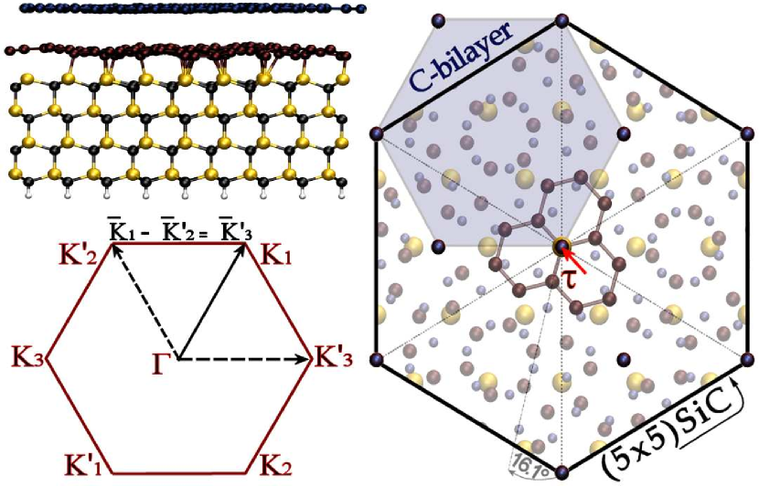
In this article we consider the electronic structure of graphene monolayers on SiC combining ab initio calculations with symmetry analysis. We derive the low energy Hamiltonian, that replaces the Dirac-Weyl Hamiltonian of a freestanding graphene. Instead of the computationally demanding structure, we adopt a strain free, commensurable (55) interface model with a corrugated carbon layer as a buffer (cf. Fig. 1). The (55) reconstruction is observed, although more rarely, on the Si-face.Riedl07 With the same buffer model for the C-face we find a much weaker graphene-SiC coupling than on the Si-face.
Backfolding of the graphene K and K′ points to the -point in the (55) Brillouin zone produces four closely lying energy branches. On the Si-face, we find that the Dirac cone is split by about 30 meV, whereas on the C-face two branches of an essentially unperturbed cone exist and the other two are separated by a very small gap ( meV). The splitting of the Dirac cones is not due to the corrugation of the graphene layer, but arises from the interaction with the substrate. We verified this by calculating the freestanding carbon layer with the same atomic positions, for which we found a perfect Dirac cone.
The buffer layer is commensurate with the SiC surface when rotated by , such that the resulting structure possesses a (55) periodicity relative to the SiC substrate (cf. Fig. 1). The following graphene epilayer can be either rotated by with respect to the buffer or aligned in AB-stacking. As seen in the right panel of Fig. 1, the (55) structure naturally results from a commensuration of the twisted carbon bilayer and the SiC surface. The (55) SiC unit cell is almost perfectly commensurate with the () graphene cell. Notably, the rotation angle of dominates in the multilayered graphene stacks Hass08 and a -rotation of the graphene bilayer relative to the SiC cell is a common feature for both Si- and C-terminated surfaces.Seyller08 ; Hass08
We used the VASP density functional packageKresse96 to obtain the interface geometry by relaxing atomic positions in the (55) unit cell and to calculate the band structures.111The calculations utilized a plane wave basis (358 eV cut-off), ultrasoft pseudopotentials [D. Vanderbilt, Phys. Rev. B 41, 7892 (1990)], LDA approximation [D. M. Ceperley and B. J. Alder, Pys. Rev. Lett. 45, 566 (1980).] and a -centered 771 k-point grid. All structures were relaxed until forces amounted less than eV/ keeping the bottom SiC bilayer at bulk position. The buffer layer shows a significant corrugation (cf. Fig. 1), that is partly transmitted into the top C-layer.
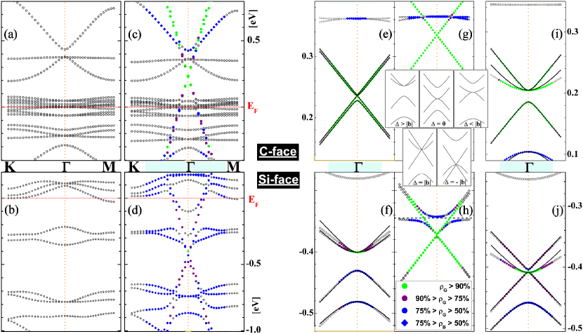
The calculated large-scale band structure is depicted in Fig. 2(a)-(d). The graphene-type linear bands appear with the second carbon layer [Fig. 2(c),(d)]. The buffer does not possess that feature, but supplies a number of flat interface states, which pin the Fermi level E [Fig. 2(a),(b)]. Owing to Fermi level pinning, the epilayer is either n- or p-doped on the Si- and C-face respectively, in accord with the measurements. Seyller08 ; Hass08 ; Miller09 It is also visible, that the resonant interaction with the interface states causes a significant distortion of the Dirac bands.
Figures 2(e)-(j) show the high-resolution energy spectra close to the Dirac point. Regardless whether the twisted or the Bernal-type structure is chosen, the energy spectrum resembles a modified single layer spectrum (with folded K and K′ points) and not a graphene bilayer spectrum. This again confirms, that the buffer does not possess the Dirac states at the K-point, i.e. it is completely passivated by the substrate. The substrate potential is rather weak, especially on the C-face, causing the band splittings in the range of . As pointed out above, the slight warping of the epilayer does not affect its band structure within an accuracy of 2 meV. Hence it should be possible to obtain the low-energy spectra by accounting for the substrate as a perturbation of the ideal graphene states. In the following we use symmetry considerations to construct the effective Hamiltonian for the graphene monolayer. The derived Hamiltonian reproduces the calculated ab initio energy spectra and can serve for the description of the quasiparticle dynamics.
Commonly, the graphene spectrum is introduced via the tight-binding modeling of the -bands. Neto09 Yet, the symmetry underlying the spectrum is much more transparently expressed within the empty lattice approach. The three states (), that correspond to the plane waves at equivalent corners of the Brillouin zone, combine into the K-point eigenstates and similarly for the time-reversed states at points . The trigonal symmetry dictates the Hamiltonian matrix
| (4) | |||||
| (5) |
where the mixing of the basis states is expressed via the symmetrized operator of a -rotation: , with the angular momentum operator in the Hilbert space . The diagonal elements in Eq. (4) are linear invariants of a small displacement from the K-point and the unit vectors . The phase of the matrix elements depends on the choice of the coordinate origin. For ideal graphene takes the values or . In an epitaxial layer, however, the inversion symmetry and hence the mirror planes of the small group are lost. This implies a reduction to and allows arbitrary values of . By time reversal the Hamiltonian at the -point is
| (6) |
Replacing by its eigenvalues () we obtain the energy levels at the K-point
| (7) |
Of special interest are the two states, that form the tip of the Dirac cone in ideal graphene. Depending on these can be any two of the levels in Eq. (7). The choice for the coordinate origin in the center of the graphene hexagon selects and .
The states and are coupled by the Umklapp process due to the substrate potential . Since we account for perturbatively, we can assume that it preserves (within the intervalley matrix elements) point symmetry of a pristine surface. However, the point group centers of the epilayer and of the substrate (i.e. of the last Si or C atomic layer) are displaced by the vector , which connects two adjacent graphene atoms (cf. Fig. 1). This displacement generates a phase factor of the intervalley matrix elements
| (8) | |||||
The shift of the coordinate origin in Eq. (8) enables us to exploit the trigonal symmetry, which requires .
Given and (cf. Fig. 1) one finds, that the phase in Eq. (8) takes values or 0. For and the phase factors can be made complex conjugated by shifting phases of the basis K-functions: , , . This, however, changes the phases in Eq. (4), such that the K-Hamiltonian takes the form
| (9) |
After this phase transformation the intervalley interaction Eq. (8) acquires a structure similar to Eqs. (6) and (9):
| (10) |
In the diagonal representation () the Hamiltonian matrix reads
| (17) |
where with the Fermi velocity . Note, that the phase shift in Eq. (9) leads to a cyclic permutation of the K-point eigenvalues. The “Dirac part” of Eq. (17) comprises the energy levels, which merge for . Introducing parameters and we obtain
| (22) |
The eigenvalues of are
| (23) |
with for different combinations of signs. Equation (23) describes the four bands originating from the K and K′ states of an ideal graphene layer subject to a symmetry lowering potential of the substrate. The spectrum of Eq. (23) takes qualitatively different forms for , and (cf. insets Fig. 2). By fitting Eq. (23) to the ab initio bands, we determine the Hamiltonian parameters as given in Tab. 1. The -twisted buffer/epilayer pair on the Si-face and the Bernal stacking on the C-face matches the case, whereas the twisted C-termination and the Bernal stacking on the Si-face correspond to the case.
| buffer/epilayer | -twisted | Bernal-type | ||
|---|---|---|---|---|
| [meV] | ||||
| Si-face | 12.7 | 21.7 | 13.5 | 11.0 |
| C-face | 2.1 | 2.1 | 20.3 | 29.9 |
The fitted bands of Eq. (23) are shown in Fig. 2(e),(f) and (j),(i). A noticeable deviation of the fit from the ab initio data occurring for some bands originates in the repulsion by the closely lying interface states (see below).
Setting in Eq. (22), becomes similar to the Hamiltonian of the freestanding twisted bilayer, where the spectrum is formed by the K-states of the two graphene layers. Due to the inequivalence of neighboring atoms, the intervalley scattering in Eq. (10) has the same structure as in the case of the “odd sublattice exchange” of the twisted bilayer.Mele10
In graphene epilayers the quasiparticle dynamics is described by the effective Hamiltonian , which replaces the Dirac-Weyl Hamiltonian of ideal graphene. An important effect, apparent in Fig. 2, is the strong resonant interaction of the Dirac bands with the interface states. This interaction should mediate a quasiparticle scattering by interface phonons. By artificially increasing the top layer separation we can trace the transition from an epitaxial to a freestanding graphene spectrum [cf. Fig. 2(g),(h)]. The band splitting as well as the resonant interaction decrease sharply, yet, the typical pattern of the resonant coupling is clearly seen in Fig. 2(h). Moreover, it is apparent in Fig. 2(h), that the resonant interaction is subject to certain selection rules: while one Dirac branch strongly couples with the interface state, the interaction matrix element vanishes for the other. Hence, the dispersion of only one Dirac band is significantly affected at equilibrium separation of the top layer [cf. Fig. 2(f),(i),(j)]. The resonant interaction is much more pronounced on the Si-face, where the coupling matrix element is about 50 meV [as estimated from Fig. 2(f)]. This is in accord with the lower carrier mobility observed on the Si-face in comparison to the C-face.Seyller08 ; Hass08 ; Orlita08 As visible in Fig. 2(c),(d), the resonant coupling also occurs close to the Fermi energy.
For a R30 SiC() surface a similar substrate-mediated interaction of the Dirac bands has to be considered, albeit with a different translational symmetry. Due to the weak coupling of the graphene layer one expects a qualitatively similar scenario. Indeed, the gap opening as well as the formation of flat interface “midgap states” were found by ab initio modelingKim08 of photoemission spectra for a R30 substrate.
The authors acknowledge financial support by the International Center for Molecular Materials (ICMM) at the University of Erlangen-Nürnberg and by the European Science Foundation (ESF) under the EUROCORES Program EuroGRAPHENE CRP GRAPHIC-RF (DFG-grant PA 516/8-1).
References
- (1) T. Seyller et al. Phys. stat. sol. (b) 245, 1436 (2008)
- (2) J. Hass, W. A. de Heer, and E. H. Conrad, J. Phys.: Condens. Matter 20, 27 (2008)
- (3) X. Wu et al. Appl. Phys. Lett. 95, 223108 (2009)
- (4) J. Jobst et al. Phys. Rev. B 81, 195434 (2010)
- (5) M. Orlita et al. Phys. Rev. Lett. 101, 267601 (2008)
- (6) S. Shallcross, S. Sharma, E. Kandelaki, and O. A. Pankratov, Phys. Rev. B 81, 165105 (2010)
- (7) X. Wu et al., arXiv:0908.4112v1
- (8) A. Mattausch and O. Pankratov, Phys. Rev. Lett. 99, 076802 (2007)
- (9) F. Varchon et al. Phys. Rev. Lett. 99, 126805 (2007)
- (10) C. Riedl et al. Phys. Rev. Lett. 103, 246804 (2009)
- (11) S. Kim, J. Ihm, H. J. Choi, and Y.-W. Son, Phys. Rev. Lett. 100, 176802 (2008)
- (12) L. Magaud et al. Phys. Rev. B 79, 161405 (2009)
- (13) F. Varchon, P. Mallet, J.-Y. Veuillen, and L. Magaud, Phys. Rev. B 77, 235412 (2008)
- (14) S. Y. Zhou et al. Nature Materials 6, 770 (2007)
- (15) L. Vitalia et al. Surface Science 602, L127 (2008)
- (16) C. Riedl et al. Phys. Rev. B 76, 245406 (2007)
- (17) G. Kresse and J. Furthmüller, Phys. Rev. B 54, 11169 (1996)
- (18) The calculations utilized a plane wave basis (358 eV cut-off), ultrasoft pseudopotentials [D. Vanderbilt, Phys. Rev. B 41, 7892 (1990)], LDA approximation [D. M. Ceperley and B. J. Alder, Pys. Rev. Lett. 45, 566 (1980)], and -centered 771 k-point grid. All structures were relaxed until forces became less than eV/ keeping the bottom SiC bilayer at bulk position.
- (19) D. L. Miller et al. Science 324, 924 (2009)
- (20) A. H. Castro Neto et al. Rev. Mod. Phys. 81, 109 (2009)
- (21) E. J. Mele, Phys. Rev. B 81, 161405 (2010)