Image Inpainting Based On Coherence Transport With Adapted Distance Functions
Abstract
We discuss an extension of our method Image Inpainting Based on Coherence Transport. For the latter method the pixels of the inpainting domain have to be serialized into an ordered list. Up till now, to induce the serialization we have used the distance to boundary map. But there are inpainting problems where the distance to boundary serialization causes unsatisfactory inpainting results. In the present work we demonstrate cases where we can resolve the difficulties by employing other distance functions which better suit the problem at hand.
keywords:
Image Processing, Image Inpainting, Distance FunctionsAMS:
65D18, 51K991 Introduction
Non-texture image inpainting, also termed image interpolation, is the task of determining the values of a digital image for a destroyed, or consciously masked, subregion of the image domain.
The simple idea of the generic single pass method – which forms the basis for our method Image Inpainting Based on Coherence Transport published in [4] – is to fill the inpainting domain by traversing its pixels in an onion peeling fashion from the boundary inwards and thereby setting new image values as weighted means of given or already calculated ones.
Telea has been the first to use such an algorithm in [12]: the pixels are serialized according to their euclidean distance to the boundary of the inpainting domain and the weight is such that image values are propagated mainly along the gradient of the distance map. By his choices of the weight and the pixel serialization, the method of Telea is not adapted to image.
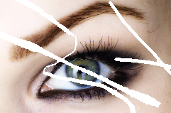
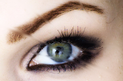
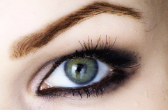
In [4], we addressed the adaption of the weight: our method uses an image dependent weight such that image values are propagated along the estimated tangents of color lines which have been interrupted by the inpainting domain. That way we could improve the quality of the inpainting results compared to Telea (see figure 1). Beyond that, we have illustrated in [4] that our method matches the high level of quality of the methods by [3], [10], [9], and [13] while being considerably faster.
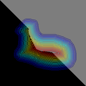
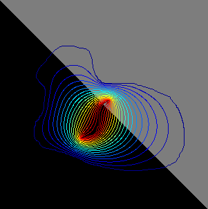
But serializing the pixels by their distance to the boundary, as Telea and we in [4] did, is not always a good idea as figure 2 illustrates. The image in the middle shows the result which we obtain by using our method with distance to boundary serialization. The diagonal is not restored and the contours of the distance to boundary map indicate that this is due to the bad location of the skeleton which consists of the ridges of the distance map. Before reaching the skeleton, however, the performance is good and the diagonal is continued tangentially. The right image of figure 2 shows the result which we get if we use another distance function (for pixel serialization) that suits the problem at hand better (see §3.1, figure 3).
The way of serializing the pixels is an important degree of freedom and in this paper we use this freedom to resolve some obstructions which the distance to boundary serialization entails. The pixel serializations that we discuss are all induced by a more general type of distance function, so the new parameter of the method is in fact the user’s choice of the distance function.
Outline of the Paper
In section 2 we summarize the existing results and give a complete description of the basic algorithm. In section 3 we turn to concrete distance functions which are used to serialize the pixels of the inpainting domain. We describe three approaches: distance by harmonic interpolation (§3.1), modified distance to boundary (§3.2), and distance to skeleton (§3.3). Section 4 closes with a discussion.
2 Summary of Existing Results
Our starting point is the generic algorithm for gray tone images. We assume that all gray tone images, seen as functions, take values in the real interval and we assume that gray tones are mapped onto such that the natural order on the interval reflects the order of the shades of gray by their brightness from black () to white (). Moreover, we will distinguish between discrete (digital) notions by using the index and continuous (analog) notions where we omit the index. Continuous notions are thought of as the high-resolution limit of the corresponding discrete ones. Finally, we identify pixels with their midpoints.
Notation
-
a)
is the image domain, the matrix of pixels for the final, restored image .
-
b)
is the inpainting domain whose values of have to be determined.
-
c)
is the data domain whose values of are given as .
-
d)
is the discrete boundary, i.e., the set of inpainting pixels that have at least one neighbor in the data domain.
Continuous quantities are defined correspondingly. Finally, we define discrete and continuous -neighborhoods by
Generic Algorithm
The basic idea is to fill the inpainting domain from its boundary inwards by using weighted means of given or already calculated image values. We assume that the pixels which are to be inpainted have already been serialized, i.e. is an ordered list. The following set
denotes the neighborhood of the pixel consisting only of known or already inpainted pixels. Then, the algorithm reads as follows:
| (1) | ||||
Here, are called the weights of the algorithm and we assume that
Pixel Serialization
In the generic algorithm, any serialization of the pixels can be used which geometrically goes from the boundary inwards in an onion peeling fashion. Now, let be a map with , , and which strictly grows into the interior of . We define the onion peels to be the level lines of . Using such a map or rather a discretized version , we serialize the pixels of by
into an ordered list .
Clearly, there are different possible choices of a suitable , but in the article [4] this degree of freedom has been fixed by setting , where is the euclidean distance to the boundary ,
As pointed out in the introduction is not always a good choice and in the next section we will use generalized distances .
Weights
Here again, different choices for the weights are possible. We consider weights of the form
| (2) |
with a kernel :
-
a)
Normal Transport (Telea’s method). Telea, in [12], uses the kernel
Tough Telea has taken , the kernel carries over to more general .
-
b)
Coherence Transport (our method of [4]). For a given guidance field called we use the kernel
(3) The guidance vector , supposed to be an approximate tangent, is computed by employing structure tensor analysis. The set-up of the structure tensor is as follows:
where and is a Gaussian kernel. The coherence vector which enters as guidance is the eigenvector of w.r.t. the minimal eigenvalue. Since depends on the image , the weight does here, too.
A Note on the Theory Behind
Because continuous theory is not an issue of this paper, we want at least make some comments. For weights of the form (2) we have shown in [4] and [6] that the high-resolution () vanishing-viscosity () limit yields transport/advection PDEs of the form:
-
a)
Normal Transport.
-
b)
Coherence Transport.
(4)
In both cases the set denotes the set where is singular. The side condition is the continuous counterpart of the pixel serialization: the function here plays the role of a Lyapunov function and this condition says that the characteristics of the advection PDE evolve strictly into the interior of and stop at . The general existence and well-posedness theory for such type of equations can be found in [8] and [7]. This theory is applied to the analog inpainting model above in [6, chapter 6].
Finally, in order to better understand the role of the parameter of the kernel , we cite two results of [4]. Firstly, according to [4, theorem 1] every weight of the form (2) corresponds to a transport field . Secondly, in [4, theorem 2], when using the coherence transport kernel , we have proved an asymptotic expansion of , w.r.t. , which implies the following limit behavior
| (5) |
That means the coherence vector guides in fact the coherence transport (4) and is the strength of this guidance.
Interface of the Algorithm
In the next section the algorithm will be performed only in its coherence transport version. That is, the weight function has the form of (2) with the kernel given by equation (3). The execution of the coherence transport algorithm depends on the choice of four parameters:
-
•
, the averaging radius,
-
•
, the guidance strength of ,
-
•
and , the scale parameters of the smoothing operations in the structure tensor .
Finally, the algorithm is supplied with the data image and a sorted list of the pixels which are to be inpainted. Any item of this list has the form
whereas are the pixel coordinates. The list is sorted in ascending order of the values.
3 Concrete Distance Functions
The generic algorithm of section 2 depends on a prescribed pixel serialization, which orders the pixels from the boundary inwards. In all previous experiments of [4] the pixels were serialized by their euclidean distance to boundary. The advantage in practice is that for all types of domains the approximate distance to boundary map is easy to generate by the Fast Marching Method (see [11] and [5]). But the disadvantage is that it is not always the best choice if one wants to get a nice looking inpainting result. Here, we present three other ways of setting up a generalized discrete distance function . We show a few synthetic examples where they yield better inpaintings than the distance to boundary.
3.1 Distance by Harmonic Interpolation
The broken diagonal is our first example. Figure 3 (b) shows the result when using the distance to boundary . The desired inpainting result would be the restored diagonal but the diagonal is only partly continued correctly. Figure 3 (c) – with the contours of overlaid – demonstrates that the undesired effect is due to the wrong location of the stop set. Figure 3 (e) shows the result when using which we obtain by prescribing a better located stop set and harmonic interpolation. Here, the algorithm is able to restore the diagonal. For both cases we have used the same set of parameters .

(a) damaged image
(b) inpainted image

(c) with contours of
(d) damaged image
(e) inpainted image

(f) with contours of
Now, we describe the construction of the discrete distance function . Here, we can prescribe the location of the stop set arcs and their distance values.
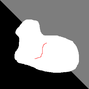
Because the boundary is the start set, the discrete distance function shall equal zero on . In addition, we take at least one or more discrete curves , , which are contained in and should belong to the stop set . Moreover, for every we specify a distance value . The remainder of then, is calculated by harmonic interpolation. That is, we solve the discrete Laplace equation
Hereby, the discretization of the Laplacian is due to the five-point-stencil
Since harmonic interpolation provides a minimum and maximum principle, our construction of can be imagined as the setting up a tent roof over the domain where are the locations of the tent poles, and every tent pole of has the length .
(a) white: , red: with
(b) contours of
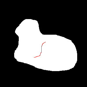
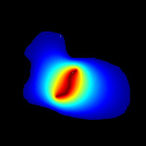
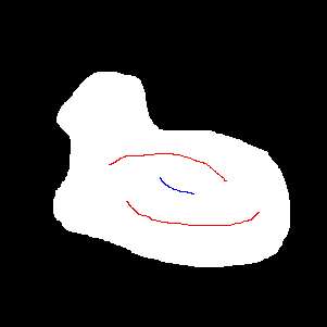
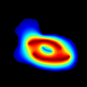
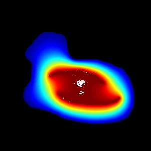
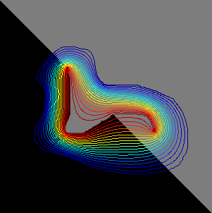
Unfortunately, not every choice of curves , with time values , results in a valid distance function: might have local minima and so would not strictly increase into the interior of . In the case of a single curve the resulting is a valid distance because of the minimum and maximum principle, see figure 4. If there are two or more curves , the question whether the resulting is valid or not depends on the location of the curves in relation to each other and the differences of their prescribed values . Figure 5 (b) shows an example with three curves , and with
Here, all points of are local minima of . But, if we keep the geometry of , and , and change the prescribed distances to
then does not have any minima (see figure 5 (c)). So, the resulting is admissible. Generally speaking, if we have two or more curves , with different prescribed distances , and if the values are chosen unfavorably, then the resulting might possess local minima on some of the .
(a) white
(b) non-valid
(c) valid
Let us review our first example. Figure 3 (e) illustrates that our – which is that shown in figure 4 (b) – works fine. More generally, if we think of as an initial scratch, which has been dilated to all of over the time , then the backward filling-in process, if is well located, makes the matching opposite sides come together. Clearly, if we deliberately place badly, then the method must fail (see figure 6, the parameters are , as before).
(a) damaged image
(b) inpainted image
(c) with contours of
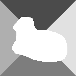
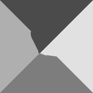
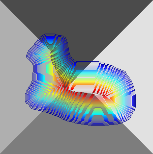
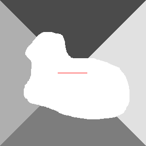
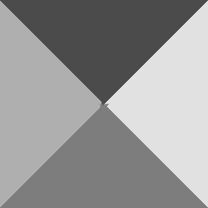
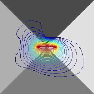
Now, we discuss two further examples. Figure 7 (a) shows two broken diagonals with the same inpainting domain as in figure 3 (a). We emphasize here that the appearance of an undesired effect depends on how the edge that needs to be continued is located in relation to the inpainting domain. In figure 7 (b) – which is inpainted using distance to boundary – the bottom-left-to-top-right diagonal is continued as desired, while the continuation of the top-left-to-bottom-right diagonal suffers from a badly located stop set. In Figure 7 (d) we have the damaged image with the single curve , shown in red. Figure 7 (e) shows the result inpainted using , the distance by harmonic interpolation. Again, a good location of makes for a good result. For both cases we have used the same set of parameters .
(a) damaged image
(b) inpainted image
(c) with contours of
(d) damaged image
(e) inpainted image
(f) with contours of
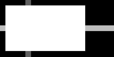
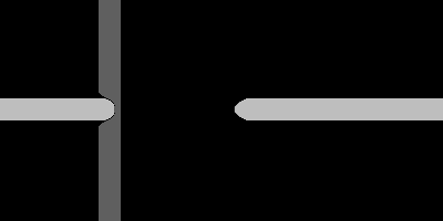
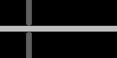
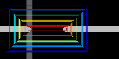
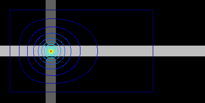
Figure 8 (a) shows a damaged cross junction. A cross junction would, in any case, geometrically be the simplest object for completion. Using the distance to boundary we obtain the result shown in figure 8 (b). Here, the stop set which is the central arc of the skeleton (see figure 8 (c)), has an unfavorable location because the bar coming from the right-hand side can never reach its counterpart. Setting as the center of the cross junction (see figure 8 (d)) and using the distance by harmonic interpolation, we are able to restore the cross junction (see figure 8 (e)). Which of the bars is closed in the end depends on the coherence strength. The brighter bar has the higher contrast w.r.t. the black background and is thus of stronger coherence. This is the reason why this bar is closed. For both cases we have used the same set of parameters .
(a) damaged image
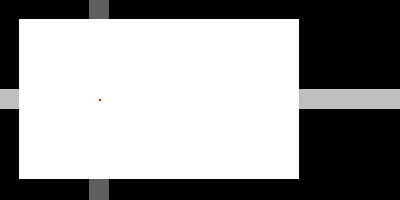
(d) damaged image, red
(b) inpainted image
(e) inpainted image
(c) with contours of
(f) with contours of
3.2 Modified Distance to Boundary
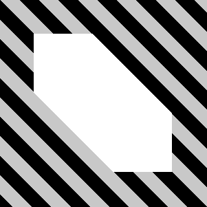
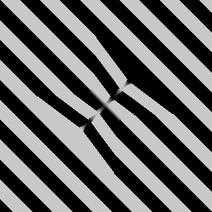
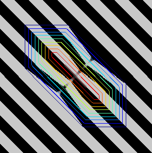
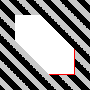
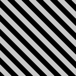
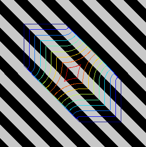
Figure 9 (a) shows a damaged stripe pattern. Performing the algorithm with distance to boundary and the set of parameters yields the result shown in figure 9 (b). The difficulty, is that the coherence vector which is tangent to the edges is orthogonal to the lower left and the upper right segment of . Thus, the transport vector switches to the normal as in the exceptional case of equation 5. Figure 9 (c) confirms the switch of the transport to .
(a) damaged image
(b) inpainted image
(c) with contours of
(d) red active boundary
(e) inpainted image
(f) with contours of
To combat this we suggest a modification of the distance map set-up. The euclidean distance to boundary map is the viscosity solution of
The modification is that we search for the euclidean distance to a subset of the boundary , i.e.,
We classify the points which shall not belong to . Assume satisfies , then the boundary normal is given by . Now, if we have at
whereas is the guidance vector, then either there is no guidance () or the guidance vector does not point inwards. Such a boundary point shall not belong to . In fact, we use the stronger condition
with a threshold parameter . Complementarily, the set of active boundary points is given by
Clearly, the new parameter must be chosen such that is not empty.
We have applied this idea to the stripe pattern: the red lines in figure 9 (d) are the active boundary points and the result is shown in figure 9 (e). Our standard parameters are , while the additional parameter is set to . The discrete approximation was computed using the fast marching method. The overlaid contour plot of in figure 9 (f) shows that the guidance vector always points inwards.
3.3 Distance to Skeleton
The third approach to obtaining a serialization is to use the distance to a prescribed stop part of the skeleton. Let , be curves in the image domain . Those curves which are contained in will later belong to the skeleton . Let, then, be the viscosity solution of
and let
The desired distance function is defined by
Warning: as in the case of harmonic interpolation (see §3.1) one must check if is admissible, i.e., if is free of local minima.
(a) damaged image
(b) inpainted image
(c) with contours of
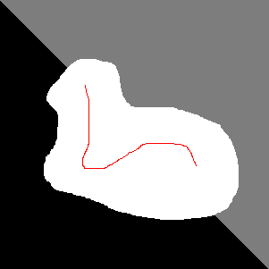
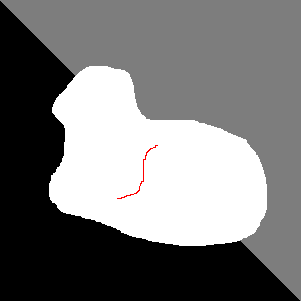
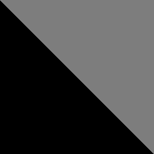
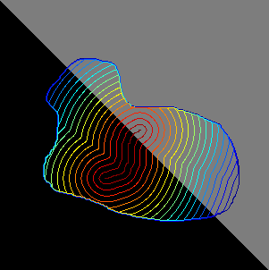
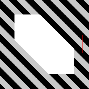
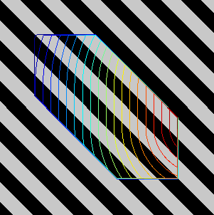
Figure 10 shows the result for the example of the broken diagonal. The red curve in figure 10 (a) defines (discrete) which shall belong to the skeleton. The discrete approximation was computed using the fast marching method and the set of parameters is , the same as we used for figure 3 (e). The inpainted result here (figure 10 (b)) is the same as in figure 3 (e), but the distance function has changed (compare figures 10 (c) and 3 (f)). If there is only one curve which is completely contained in , then distance by harmonic interpolation (with ) and distance to skeleton will yield very similar results. If there are two or more curves, then distance by harmonic interpolation allows for different distance values on , while distance to skeleton has exactly one distance value on all of the curves . In contrast to distance to skeleton, the distance by harmonic interpolation method requires .
(a) damaged image
(b) inpainted image
(c) with contours of
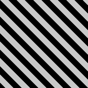
Moreover, since is defined on , we can place outside of the inpainting domain . We use this possibility to restore the stripe pattern in figure 11. The parameters are , the same as we used for figure 9. It is obvious from the level lines of (see 11 (c)) that the guidance vector always points inwards. Thus, we get the desired result again here.
Remark: The construction here, as well as that of §3.2 produces distance functions whereas not the whole boundary belongs to the start set. Besides that, it is possible that parts of the boundary belong in fact to the stop set.
4 Discussion
In the previous section we have demonstrated that there are inpainting problems where a distance to boundary induced serialization of the pixels is not favorable and we have constructed other distances which are able to resolve the difficulties which appear.
So far we have considered synthetic images, because their image geometry is easy to understand. Thus, we were able to construct distances which are adapted to the image or rather to an expected result. When we face natural inpainting problems, as shown in figures 1 (left) and 12 (a), it is not as easy to set up an adapted distance function. This is because
-
•
the geometry of the image is harder to understand,
-
•
the damaged region is complicated.
Moreover, if the damaged region consists of many connected components and one wants to use our distance by harmonic interpolation technique (§3.1 ), one must prescribe arcs for every single component of connectivity; for the example of figure 12 (a) that means for every single letter. This can be time consuming (for the user, not for the computer).
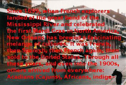
(a) original image (courtesy of [3, figure 6])
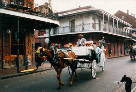
(b) inpainted:
In contrast, the distance to boundary map can be computed fast and easily for every type of inpainting domain. And, inpainting using distance to boundary often produces results of high quality when applied to natural inpainting problems (see figures 1 (right) and 12 (b)). This is because for natural inpainting problems the damage often is such that color lines have been broken by scratches (By scratches we mean rather thin and lengthy damages). If the damage is of this type, the skeleton of , being a simplified version of the scratch, is well placed and so the filling-in process makes the matching opposite sides come together. The images shown in figures 1 (right) and 12 (a), like many other natural inpainting problems, have this type of damage. Thus, our inpainting method using distance to boundary is able to produce results pleasing to the eye.
5 Acknowledgements
The author would like to thank Folkmar Bornemann for his advice and the inspiring discussions.
References
- [1] T. Aach, C. Mota, I. Stuke, M. Mühlich, and E. Barth, Analysis of superimposed oriented patterns, IEEE Trans. Image Process., 15 (2006), pp. 3690–3700.
- [2] L. Alvarez, F. Guichard, P.-L. Lions, and J.-M. Morel, Axioms and fundamental equations of image processing, Arch. Ration. Mech. Anal., 123 (1993), pp. 199–257.
- [3] M. Bertalmio, G. Sapiro, V. Caselles, and C. Ballester, Image inpainting, in SIGGRAPH ’00: Proceedings of the 27th Conference on Computer Graphics and Interactive Techniques, New Orleans, New York, 2000, ACM Press/Addison-Wesley, pp. 417–424.
- [4] F. Bornemann and T. März, Fast image inpainting based on coherence transport, J. Math. Imaging Vision, 28 (2007), pp. 259–278.
- [5] R. Kimmel, Numerical Geometry of Images, Springer-Verlag, New York, 2004.
- [6] T. März, First Order Quasi-Linear PDEs with BV Boundary Data and Applications to Image Inpainting, PhD thesis, Technische Universität München, http://nbn-resolving.de/urn/resolver.pl?urn:nbn:de:bvb:91-diss-20100429%-977864-1-6, 2010.
- [7] , On the dirichlet problem for first order hyperbolic pdes on bounded domains with mere inflow boundary: Part ii quasi-linear equations, Preprint, arXiv:1008.5110, (2010).
- [8] , On the dirichlet problem for first order linear hyperbolic pdes on bounded domains with mere inflow boundary, Preprint, arXiv:1008.3480, (2010).
- [9] S. Masnou, Disocclusion: a variational approach using level lines, IEEE Trans. Image Process., 11 (2002), pp. 68–76.
- [10] S. Masnou and J. Morel, Level lines based disocclusion, in ICIP ’98: Proceedings of the 1998 IEEE International Conference on Image Processing, Chicago, New York, 1998, IEEE Press, pp. 259–263.
- [11] J. Sethian, Level Set Methods and Fast Marching Methods, Cambridge University Press, Cambridge, 2nd ed., 1999.
- [12] A. Telea, An image inpainting technique based on the fast marching method, J. Graphics Tools, 9 (2004), pp. 23–34.
- [13] D. Tschumperle, Fast anisotropic smoothing of multi-valued images using curvature-preserving pde’s, Int. J. Comput. Vision, (2006), pp. 65–82.
- [14] J. Weickert, Anisotropic Diffusion in Image Processing, B.G. Teubner, Stuttgart, 1998.