Measurement of the neutron electric dipole moment via spin rotation in a non-centrosymmetric crystal
Abstract
We have measured the neutron electric dipole moment using spin rotation in a non-centrosymmetric crystal. Our result is . The dominating contribution to the systematic uncertainty is statistical in nature and will reduce with improved statistics. The statistical sensitivity can be increased to in 100 days data taking with an improved setup. We state technical requirements for a systematic uncertainty at the same level.
keywords:
electric dipole moment , CP violation , perfect crystal , neutron , diffraction , three-dimensional polarisation analysisPACS:
14.20.Dh , 61.05.fm , 04.80.Cc1 Introduction
Electric dipole moments (EDMs) of elementary particles belong to the most sensitive probes for CP violation beyond the Standard Model of Particle Physics [1]. Constraining or detecting EDMs of different systems allows to gather experimental information about models for new physics that is complementary to high energy physics data.
For the neutron EDM (nEDM), the most sensitive results [2, 3] were obtained using ultracold neutrons and Ramsey’s resonance method. See [4] for a recent review of measurements using free neutrons. Measurements using the interaction of neutrons with the atomic electric field in absorbing matter were pioneered by Shull and Nathans [5]. Abov and colleagues [6] first discussed a spin-dependent term in the scattering amplitude for neutrons in non-centrosymmetric non-absorptive crystals. This term is caused by the interference of nuclear and spin-orbit structure amplitudes. Forte [7] proposed to search for nEDM related spin rotation in non-centrosymmetric crystals due to such interference. In [8] it was pointed out that such interference leads to a constant interplanar electric field affecting the neutron during all time of its passage through the crystal. This field was measured first in [9]. The interference of nuclear and spin-orbit structure amplitudes was tested by Forte and Zeyen [10] by spin rotation in a non-centrosymmetric crystal.
Here we present the first measurement of the nEDM based on an improved version of this method. Preliminary results and a detailed description of our method with references to earlier work have been published in conference proceedings [11, 12].
The statistical sensitivity of any experiment to measure the nEDM is determined by the product , where is the value of the electric field, the duration of the neutron’s interaction with the field and the number of counted neutrons. New projects to measure the nEDM with UCNs aim to increase the UCN density and thus by orders of magnitude and exploit in some cases the higher electric field obtainable in liquid helium compared to vacuum [13, 14]. In contrast, experiments with non-centrosymmetric crystals exploit the interplanar electric field. For quartz, this field was measured to be V/cm [9], several orders of magnitude higher than the electric field achievable in vacuum or liquid helium. Furthermore, the statistical sensitivity of the method profits from the higher flux of the used cold neutrons, compared to UCNs available today. These factors compensate the shorter interaction time of the neutrons with the electric field, ultimately limited by the absorption in the crystal. In [15] we have demonstrated that a statistical sensitivity of can be obtained, comparable to the most sensitive published UCN experiments [2, 3].
2 Method
We consider spin rotation for neutrons close to the Bragg condition for the crystallographic plane in a non-centrosymmetric crystal. These neutrons are exposed to an electric field where is the interplanar electric field for plane and describes the deviation of the neutron from the exact Bragg condition (see [11] for details). A nonzero nEDM results in neutron spin rotation by the angle
| (1) |
where is the length of the crystal and the component of the neutron velocity perpendicular to the crystallographic plane ( is the time the neutron interacts with the field). By changing the deviation from the exact Bragg condition, , value and even sign of the effective electric field and the resulting spin rotation can be selected.
On the other hand, the electric field causes a Schwinger magnetic field in the rest frame of the neutron, , resulting in the spin rotation angle
| (2) |
where is the neutron magnetic moment and the neutron velocity component parallel to the crystallographic plane.
As and are perpendicular to each other, and can be separated by three-dimensional (3D) polarisation analysis. Furthermore, vanishes for Bragg angles of ( in Eq. (2)). This is used to suppress the effect due to Schwinger interaction: The crystal is aligned such that the interplanar electric field is parallel to the central neutron velocity, defining the direction of a coordinate system. The incident neutron polarisation is aligned in (or ) direction. is measured in the - plane. A residual Schwinger magnetic field (for neutron trajectories deviating from the direction or in case of a slight misalignment of the crystal) has its largest component in the - plane, thus creating a polarisation component in direction. Thus, can be derived from the component of the outgoing polarisation vector. In summary, we measure from the component of the polarisation tensor and the residual Schwinger effect from the components and . , and serve for control purposes.
In first order, the difference of the polarisation tensors for positive and negative effective electric fields is:
| (3) |
where , , and and are the times the neutrons stay in the crystal for the positive and the negative electric field, respectively (the neutron velocity is slightly different for ). are the components of the residual magnetic field and the components of the Schwinger magnetic field . is the neutron gyromagnetic ratio, the effective magnetic field corresponding to the electric field . For V/cm and , G.
3 Experimental setup and procedure
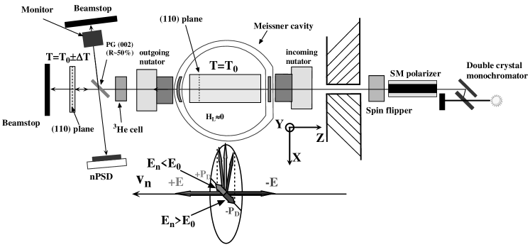
The experiment was carried out at the cold neutron beam facility PF1B [17] of the Institut Laue-Langevin. A scheme of the setup is shown in Fig. 1. Neutrons were wavelength-preselected by a pyrolytic graphite monochromator (adjusted to 4.91 Å, resolution about 1%) and spin polarised to about 98% by a super mirror polariser. A resonance spin flipper permitted to flip the neutron polarisation. Cryopad [18, 19] was used for 3D polarisation analysis. The direction of the incident beam polarisation was oriented and the measured projection of the outgoing polarisation vector selected by nutators (in the - plane) and precession coils (inside the Meissner screen, for the component). The polarisation of the transmitted beam was analysed by a 3He spin filter cell [20] (measured polarisation value of the unperturbed beam between 75% and 87%, depending on the 3He cell). The currents in the precession coils were optimised experimentally for the wavelength of the used neutrons.
We used the (110) reflection of a perfect quartz crystal of 14 cm length. The effective angular mosaic spread of the crystal was . The neutrons with a well-defined deviation from the Bragg condition for this crystal were selected behind the 3He spin filter cell by back-reflection at a second quartz crystal oriented parallel to the first one and at a slightly different temperature. A shift of the neutrons by one Bragg width ( for the (110) plane of quartz) corresponds to a temperature difference K (linear coefficient of thermal expansion for quartz ). Note that the absolute temperature of the crystals is not important. The crystals were temperature stabilised in individual housings connected by a common water circuit. The temperature of the second crystal was varied by Peltier elements.
The back-reflected neutrons were separated from the beam by a pyrolytic graphite monochromator (PG (002)) with a reflectivity of about 50% and directed to a position sensitive detector (nPSD). The nPSD allowed us to analyse data depending on the deviation of the neutron’s path from the direction: Larger deviations correspond to larger and thus . This monochromator unavoidably reflects about 50% of the neutrons after the spin filter, before the second quartz crystal. These neutrons were used to monitor intensity and polarisation.
During installation, the crystals were pre-aligned optically using an autocollimator. Final alignment was performed with neutrons, allowing for the possibility of slightly different lattice constants of the crystals at the same temperature: The intensity of the neutron beam backscattered by the second crystal has a minimum if the Bragg condition of the second crystal (varied by the temperature difference) corresponds to the Bragg condition of the first one. If the crystal planes of both crystals are parallel, this minimum has the smallest width. The alignment with the minimum width was found by scanning the temperature difference for different angles (in and direction) of the second crystal. Data show that the lattice constants were equal for K [11], which can be attributed to slightly different impurities of the two crystals. From previous measurements [21] we selected the working points with maximal electric field magnitude K and K.
The different measured combinations of electric field direction and components of the polarisation tensor are , where the index refers to the temperature difference of the crystals . The indices and indicate the directions of the incident and outgoing neutron polarisation selected by Cryopad. Each component was measured for 40 s by flipping the incident neutron polarisation every 1-4 s with the resonance flipper (states off, on), in a drift-compensating scheme . The different states were measured in drift-compensating cycles, one for the EDM effect, , , , , , , ,, and one for the Schwinger effect, , , , , , , , . EDM data were taken 2/3 of the total time, Schwinger data due to the smaller required statistics only 1/3. The dominating drift originated from the depolarisation of the 3He cells with time (time constants large compared to a single cycle).
4 Results
From the measured data we determined the elements of the difference of the polarisation matrices, . The Schwinger data showed the expected linear variation over the nPSD: neglecting the spatial extension of the beam, the deviation of a neutron from the centre of the nPSD is proportional to . Fig. 2 shows a linear fit to the data . This allows us to derive the electric field acting on the neutrons:
| (4) |
This value is consistent with our preliminary result obtained for the Bragg angle [21].
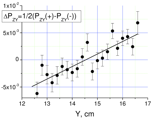
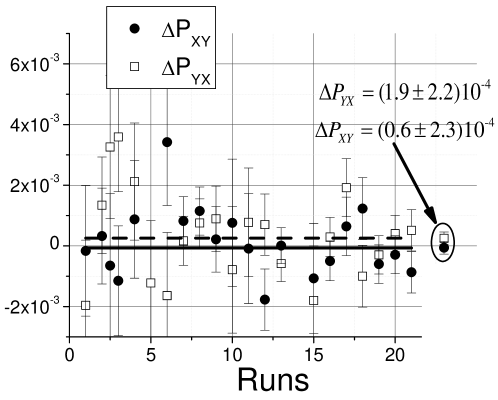
Fig. 3 (top) shows an example for the spatial dependence of the matrix element sensitive to the nEDM. The summary of all accumulated data for the nEDM is presented in Fig. 3 (bottom). The average value for the nEDM spin rotation is
| (5) |
corresponding to the nEDM (see Eq. (1)) .
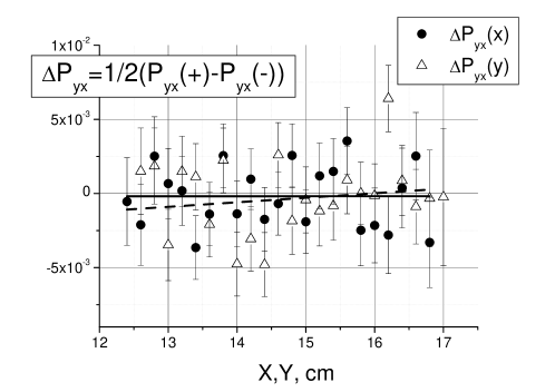
The slope of the spatial dependencies of and is related to the Schwinger effect. It was found to be consistent with zero and used to estimate a related systematic uncertainty of . Note that this uncertainty is smaller than the statistical uncertainty of the nEDM taken from the same data and would reduce with better statistics. It includes the error caused by imperfect angular accuracy of the 3D polarisation analysis (if the analysed component is not perpendicular to the - plane, the corresponding projection of the Schwinger effect would contribute to and ).
The residual magnetic field inside Cryopad was mG. The reversal of the electric field leads to a small change of the neutron wavelength and thus to a difference of the time the neutron stays inside Cryopad. This time difference was measured directly: . The combination of the residual magnetic field and the time difference results in a systematic uncertainty of .
The time stability of the experiment was controlled by the beam monitor, which registered neutrons behind Cryopad without interaction with the second quartz crystal. The average electric field acting on these neutrons was about zero (taking into account the wavelength distribution in the neutron beam, it was times less than the field for the neutrons that would be selected by the second quartz crystal). The difference in polarisation measured by the beam monitor between the two working points, , can be used to limit a possible systematic effect due to beam fluctuations in time, .
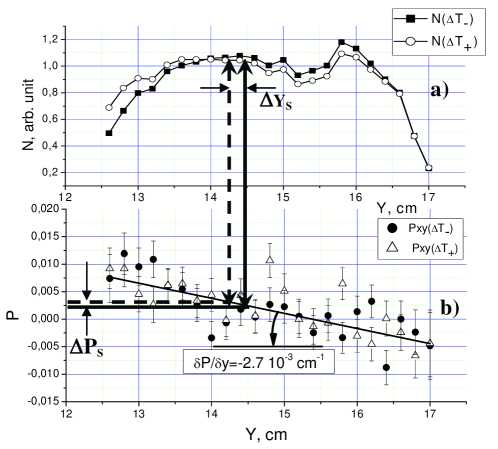
We have observed a spatial shift of the neutron beam at the nPSD correlated with the working point (see Fig. 4a), caused by an imperfect alignment of the two quartz crystals, and a spatial dependence of the polarisation (see Fig. 4b), probably due to the cylindrical shape of the outgoing window of Cryopad and the presence of a residual magnetic field. The combination of both effects causes a systematic error of . For the final crystal alignment cm this corresponds to and .
Spin rotation caused by the weak interaction cancels for the two crystal temperatures in first order. The cancellation is incomplete because of a cross term of weak and Schwinger rotation, but the uncompensated part is below of the weak spin rotation and can be neglected.
Summing these independent systematic errors we obtain the final result
| (6) |
Note that the systematic error is mainly statistical in nature. This result is about two orders of magnitude less precise than present experiments using UCNs and Ramsey’s resonance method.
5 Outlook
The statistical sensitivity of the experiment described above was . In [11] we have shown that the sensitivity can be improved by a factor 65 to about , essentially by increasing the divergence acceptance of the installation, the beam size, and the crystal length. This improved sensitivity is comparable to state-of-the-art nEDM measurements using UCNs and permits a statistical uncertainty at the level in a beam time of 100 days. A further improvement may be possible by using crystals with higher interplanar electric fields. However, these crystals are presently not available in the required quality and size.
In Table 1 we list the experimental parameters that are required for an adequate systematic uncertainty. The values are achievable. Note that a variation of the interplanar distance in the crystal of the order of the Bragg width or larger does not simulate an nEDM but reduces the magnitude of the effective electric field.
| Parameter | Value | |
|---|---|---|
| Interplanar distance variation | ||
| Residual magnetic field | ||
| Value | G | |
| Time stability | G/h | |
| Accuracy of 3D polarisation analysis | rad | |
| Angular crystals alignment | ||
| Precision of temperature control | K | |
| Flatness of Cryopad windows | rad | |
We conclude that neutron spin rotation in quartz in Bragg geometry permits to measure the nEDM with a precision comparable to existing UCN experiments but using a completely different method. Efforts are now being made to produce larger crystals and a version of Cryopad optimised for that kind of measurements.
Acknowledgements
The authors would like to thank the personnel of the ILL reactor (Grenoble, France) for technical assistance in the experiment. This work was supported by RFBR (grants No 09-02-00446).
References
- [1] M. Pospelov and A. Ritz, Annals of Physics 318 (2005) 119.
- [2] C.A. Baker, D.D. Doyle, P. Geltenbort, et al., Phys. Rev. Lett. 97 (2006) 131801.
- [3] I.S. Altarev, Yu.V. Borisov, N.V. Borovikova, et al., Yad. Fiz. 59 (1996) 1204.
- [4] S.K. Lamoreaux and R. Golub, J. Phys. G 36 (2009) 104002.
- [5] C.G. Shull and R. Nathans, Phys. Rev. Lett. 19 (1967) 384.
- [6] Yu.G. Abov, A.D. Gulko, and P.A. Krupchitsky, Polarized Slow Neutrons, (Atomizdat, Moscow, 1966) 256p. (in Russian).
- [7] M. Forte, J. Phys. G 9 (1983) 745.
- [8] V.L. Alekseev, E.G. Lapin, E.K. Leushkin, et al., JETP 67 (1988) 1727.
- [9] V.L. Alexeev, V.V. Fedorov, E.G. Lapin, et al., Nucl. Instr. and Meth. A 284 (1989) 181; JETP 69 (1989) 1083.
- [10] M. Forte and C.M.E. Zeyen, Nucl. Instr. and Meth. A 284 (1989) 147.
- [11] V.V. Fedorov, M. Jentschel, I.A. Kuznetsov, et al., Nucl. Instr. and Meth. A 611 (2009) 124.
- [12] V.V. Fedorov, M. Jentschel, I.A. Kuznetsov, et al., Nucl. Phys. A 827 (2009) 538.
- [13] M.G.D. van der Grinten, Nucl. Instr. and Meth. A 611 (2009) 129.
- [14] I. Altarev, G. Ban, G. Bison, et al., Nucl. Instr. and Meth. A 611 (2009) 133.
- [15] V.V. Fedorov, E.G. Lapin, E. Lelièvre-Berna, et al., Nucl. Instr. Meth. B 227 (2005) 11.
- [16] V.V. Fedorov, E.G. Lapin, S.Y.Semenikhin, et al., Int. Journ. Mod. Phys. A 23 (2008) 1435.
- [17] H. Abele, D. Dubbers, H. Häse, et al., Nucl. Instr. and Meth. A 562 (2006) 407.
- [18] E. Lelièvre-Berna, P.J. Brown, F. Tasset, et al., Physica B 397 (2007) 120.
- [19] E. Lelièvre-Berna, Novel polarized neutron tools, in I. Anderson and B. Guerard (eds.), Advances in Neutron Scattering Instrumentation, Proceedings of SPIE 4785 (2002), ISBN 0-8194-4552-5, pp. 112-125.
- [20] A.K. Petoukhov, K.H. Andersen, D. Jullien, et al., Physica B 385 (2006) 1146.
- [21] V.V. Fedorov, I.A. Kuznetsov, E.G. Lapin, et al., Nucl. Instr. and Meth. B 252 (2006) 131.