Cherenkov Light Imaging – Fundamentals and recent Developments
Abstract
We review in a historical way the fundamentals of Cherenkov light imaging applied to Ring Imaging Cherenkov Counters. We also point out some of the newer developments in this very active field.
keywords:
RICH , History1 Introduction
In the early 1930’s Pavel A. Cherenkov, under the guidance of his adviser Sergey I. Vavilov, investigated the nature of light emitted by radioactive minerals. Eventually it became clear that he observed a new phenomena, later called Cherenkov or Vavilov-Cherenkov radiation. The electrons from the -decay with a velocity larger than the velocity of light in a medium (in Cherenkov’s case water) with refractive index emit light under a fixed (Cherenkov)-angle given by [1]
| (1) |
Shortly afterwards Ilja M. Frank and Igor Y. Tamm brought forward a theory explaining not only the emission angle, but also the intensity and wavelength (or energy) dependence [2]:
| (2) |
Cherenkov, Frank, and Tamm shared the 1958 Nobel Price for this discovery.
2 Fundamentals of Ring Imaging
The basic components of a detector or detector system utilizing the Cherenkov effect are: (1) a radiator (2) a photon detection system, and (3) optional some focusing elements like mirrors or lenses. Examples of Cherenkov detectors include water tanks lined with large photomultipliers like SuperKamiokande [3] or SNO [4], working in an effective Proximity Focusing mode; Ring Imaging Cherenkov Counters (RICH) with gas radiator and mirrors like in SELEX [5], and DIRC (detection of internally reflected Cherenkov light) counters like in BaBar [6].
The first mentioning (altough not with this name) of a Ring Imaging Cherenkov Counter is an article by Arthur Roberts “A new type of Cherenkov detector for the accurate measurement of particle velocity and direction”, published in 1960 [7]. The abstract reads:
…The image is a ring, whose diameter measures accurately the Cherenkov cone angle, and thus the particle velocity. In addition the coordinates of the center of the circular image accurately indicate the orientation of the particle trajectory (though not its position)…
Only in the 1970’s larger area photon detection became possible thanks to the work of Tom Ypsilantis and Jaques Sequinot [8], using TEA and later TMAE as photo-sensitive agents within multiwire- or drift-chambers to detect the released electron(s).
In addition to the huge PMT’s employed in the Water Cherenkov detectors, during the 1980’s small photomultipliers (as small as diameter) were employed in RICH detector prototypes in Protvino [9].
2.1 Ring Imaging Cherenkov – The Basics

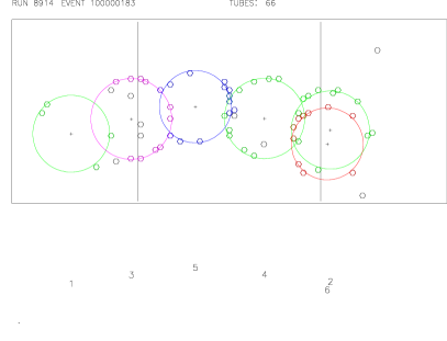
As shown in fig. 1 the Cherenkov photons emitted under an angle with respect to the particle trajectory in a radiator with refractive index are focused (in the small angle approximation) by a spherical mirror of radius onto a focal sphere of radius (thus the focal length ) where the photons form a ring of radius given by
| (3) |
while is given by equation 1. The number of detected photons is usually expressed in the form
| (4) |
where is the radiator length (usually , but folding the light path with flat mirrors is possible), and is the “figure of merrit” describing the quality and wavelength interval of the photon detection system, first introduced in [8]. In fig. 2. the final ring images in a multitrack event are shown111This image was used within the RICH2004 conference poster..
In the small angle approximation, equation 3 yields
| (5) |
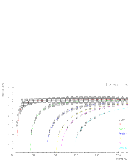
where is the mass and is he momentum of the particle producing the Cherenkov light. Thus, knowing (measured in a magnetic spectrometer) can be obtained, e.g. the particle can be identified; also possible is the opposite, knowing (or assuming) or can be obained.
The first RICH detector showing a scatter plot of ring radius versus momentum with real experiment data is the E605 RICH detector [11] in 1983, with , where the curves for and can barely be seen. 20 years later, in 2003, SELEX published [12] a plot with all 16 stable particles clearly visible in the scatter plot. Figure 3 shows the plot for postive tracks.
The angular separation between two particles of masses and is given by
In hadro-production experiments this means that usually pions and kaons are the particles which are most difficult to separate in a RICH detector, because electrons and muons are identified by other means; but really the smallest separation is between muons and pions, which is actually used as a key feature in the velocity spectrometer concept pioneered by CKM [13, 14] and used in NA62 [15, 16]. After all these preliminary statements it looks like that a RICH Detector is as simple as a radiator box, some mirrors, and a few phototubes. This is obviously not the case, and we will elaborate on this in the following parts.
2.2 Short History of RICHes in Experiments
As mentioned earlier, a first generation of RICH detectors were employed in experiments in the early 1980’s. Examples include Fermilab E605 [11], experiments WA69 [17] and WA82 [18] at the CERN Omega-Spectrometer, and Fermilab E665 [19]. These detectors suffered from operational problems, and only had a limited contribution to the physics results of the experiments. Second generation detectors, based on the (positive and negative) experiences gained earlier, were used at the end of the 1980’s and beginning of 90’s. Examples include an upgraded Omega RICH [18] used by WA89 [20] and WA94 [21], Delphi [22], SLD-GRID [23, 24], CERES [25, 26], and SPHINX [27]. These detectors reached about half of the originally expected number of detected photons, but all the losses could be eventually accounted for by carefully determining all the operational parameter; one large problem was the TMAE quantum efficiency and electron attachment length depending on the cleaning proceedure of the TMAE [28, 29]. These detectors still presented some operational challanges, but generally contributed to the physics ouput of the experiments. The third generation, build and used during the mid-90’s, like SELEX [5], Hermes [30, 31, 32, 33], and Hera-B [34, 35, 36], reached their designed performance parameters from the very beginning, were reasonable easy and stable to operate, and made essential contributions to the physics results. The fourth generation detectors, like BaBar–DIRC [6, 37], CLEO–III [38, 39, 40], COMPASS [41, 42, 43], are all well understood devices, do not present too much operational problems, and are part of the physics analysis of the experiment. Newer generation devices, like the RICHes in LHCb [44, 45, 46] and ALICE [47, 48, 49], are just starting operation, and at this conference first results will be presented. There are two more RICH projects which were cancelled due to internal politics in the USA; we should have been able to see first results from the BTeV [50] and CKM [13, 14] RICHes. There is a long list of detectors in different stages of planning and construction, like the RICHes for BELLE II [51], NA62 [15, 16], Panda [52], CBM [53, 54], and many more.
2.3 RICH – The Reality
In this section we will discuss some of the obstacles encountered while designing and operating a RICH detector. Most of these points are now (today) well understood, but earlier generation RICHes suffered with them.
2.3.1 Detector surface
Obvious from fig. 1 (and also mentioned by A. Roberts) is the fact that the ring center is given by the track angle and not by the track position. Since most RICH detectors are placed downstream of a magnetic field used the measure the track momentum, the photon detector has to cover a large surface area, as shown in fig. 4.

But still the photon position should be measured with sufficient accuracy (given by equation 2.1), so in general one ends up with a huge number of “pixels” of some kind of photon detector.
2.3.2 How to select the refracive index ?
Most (but not all) photon detectors operate in the ultraviolet or even VUV region, because due to the higher photon energy it is generally easier to effectively detect the photon. Since the RICHes are usually placed downstream of a magnetic field and lower momentum particles are deflected and do not reach the RICH detector, a typical selection for the pion threshold (and thus ) is the minimum momentum of the particles reaching the detector. But also the contrary is used, for example in the hadron-blind CERES RICH [25]. Tables for the refractive indexes for different materials are readely available (see for example [56]). In case the desired is not directly available, one can use (over- and under-)pressure or mixtures to obtain it. One has to be extremely carefull in matching the choice of (gas-)radiator with the sensitive wavelength range of the photon detection system. The refractive index depends on the wavelength (), and diverges close to an absorption line of the gas, leading to a smearing of the Cherenkov angle and to a loss of resolution (called “chromatic dispersion”). Early measurements of this wavelength dependence in the VUV region were not very accurately done, but correct parametrizations are now available and can be found in [57, 58]. At the very end one has to find an equilibrium between the number of photons detected (usually meaning extending the range to lower wavelengths) and the cost of larger chromatic dispersion. Once the refractive index (or the gas) is selected, one has to check if the resolution at high momentum (see equation 2.1) is good enough for the experiment. If not, there are several possible solution, all of them adding additional complications and costs to your detecter: smaller (and more) pixels (only if pixel size is resolution limit); larger mirror radius (focal length), which mean larger area of the photon detector with more pixels; more than one radiator to cover different momentum regions (examples: Delphi, SLD, Hermes, LHCb). In any case you should try to seal the radiator system so the refractive index will not change over time. This is not always possible, for example when large windows separate the radiator from the detection volume.
2.3.3 Proximity Focusing
If the radiator material has a large refractive index (like glas or liquid) the number of photons emitted is large (equation 2, ). A “thin” radiator yields a small width ring; if the width is small enough for the desired resolution, no focusing elements are needed. An extrem application of this method are the Water Cherenkov Detectors which separate muon from electrons without any focusing elements.
2.3.4 Mirrors
The mirror radius is usually twice the radiatior length, but also other geometries with tilded flat mirrors are possible. Mirrors have to be “thin” (small interaction and radiation length) to avoid interactions and conversions; but remember that the radiator itself also is material! The surface quality has to be “good enough” as not to be the resolution limit. Typically the surface quality can be worse than needed for astronomical applications, and allows to produce thinner mirrors. The parameters (average radius, quality) of every single mirror has to measured; we recommend the Ronchi Method [59, 60, 61] to determine a complete map of the mirror surface. The reflectivity has to be high and has to cover the full range of the wavelength sensitivity of the photon detection system, usually extending to the VUV; reflectivities above at can be achieved. Best would be a single mirror, but usually this is not possible due to size restrictions at the production or coating facilities, or the thickness and surface quality requirements. But several mirror segments can be mounted to form one larger mirror, with some effort on alignment (hardware and software). The optimum size for a mirror seems to be the radius of a ring; this facilitates the alignment during operation of the detector.
2.3.5 Photon Detection System
The general design of RICH detectors seems to be that the number of detected photons for a ring is around 15. For the photon detection we have to be aware that Cherenkov photons are single photons; noise sources in the system have to be below the one photon equivalent. The general way to detect a photon is via the photoelectric effect, converting the single photon into a single electron, or (in semi-conductor devices) into an electron-hole pair. Early RICH detectors used photon-sensitive vapors like TEA or TMAE for the conversion, and a MWPC, a TPC or TEC to detect the electron. A window separating the radiator from the photon detector is necessary, and has to be transparent to the photons which have enough energy to ionize the vapor. Also the counting gas in the chamber has to transparent for the relevant photons. In the classical geometry (see fig. 1) the charged particle itself could pass thru the chamber, leaving a huge signal (typically a few hundred electrons) in the chamber and disturbing the measurement of the only photo-electron.

An example for this is the online event display from the WA89 (upgraded Omega) RICH in figure 5. The classic photon detector, the photomultiplier, is used in sizes up to diameter in Water Cherenkov detectors; and as small as 13mm in RICH detectors. PMTs are used when the number of pixel required is not too large; the largest PMT system (BaBar) has about 10000 channels. Other photon detectors used or planned to be used are: Multi-Anode PMTs, Microchannel Plates, Hybrids (photocathode with Silicon Strip/Pixel Detector), CsI photocathode with a “GEM” to detect the electron, and solid state (silicon) devices. All of them have dedicated talks or full sessions within this conference.
2.4 Contributions to total resolution
All the parts making up the full Cherenkov detector system have some influence on the performance, usually expressed as the single hit or the ring radius resolution. From there we can deduce the separation between two particle hypotheses at a given momentum, usually expressed in units of the ring radius resolution, which is assumed to be Gaussian. The sum of the single pieces has to coincide with the measured total resolution or separation; only when the sum comes out correct the detector system is fully understood. In the first RICH detectors the so-called plot was used to calibrate and evaluate the performance of the detectors. The procedure is the following: Predict the ring center location using the track parameters obtained independently; assume that all tracks a pions; assume all hits in your detector belong to this track and calculate with equation 5 the apparent , and fill a histogram. An example is shown in fig. 6.

3 Recent Developments
Before we give a summary of new developments for Cherenkov detectors,
we will take a short detour and ask ourself if Cherenkov detectors are still
employed actively and used in new experiments. As an indicator we
used papers contained in the
SPIRES database222http://www.slac.stanford.edu/spires.
We searched for
all titles containing the words
RICH or Ring Imaging or cherenkov or tscherenkov
or cerenkov
for every year since 1970. The results we
divided by hand into the following Categories:
Water (and Ice) Cherenkov Detectors
Threshold (and similar like DISC) Counters
Atmospheric Cherenkov and Astronomy
Calorimeters (lead glass and similar)
Physics Results from Cherenkov detectors
Cherenkov Theory
Ring Imaging Cherenkov
and we excluded papers about accelerator techniques333Pavel Cherenkov
was active in this field as well..
As shown in fig. 7 the total number of publications is
increasing (with some peaky structure discussed later),

indicating that the field is still interesting and in active development. If we separate the publications in the different fields mentioned above (fig. 8),
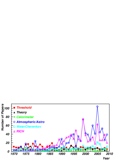
we can see that Atmospheric Cherenkov and RICH papers have the largest numbers of publications, with the peaks in astronomy coinciding with the International Cosmic Ray conferences; and the (not as prominent) peaks for RICH papers with the RICH and other detector conferences. The number of paper treating “conventional” detectors, like Threshold Counters, is small but constant. Most (but not all!) are (highly sophisticated!) “optimizations” of the “basics” discussed before, but there are also new developments which we will discuss in the following. The description of the new developments will be short, because all of them have talks or even full sessions assigned at this conference.
3.1 News on Mirrors
The main problem to be solved for the mirrors is still the same: they have to be thin (small , ) but mechanically stable. 20 years ago CERES [25] had (one!) mirror made of carbon fibre, but there seems still problems to be solved, like in the case for the LHCb Mirrors.
3.2 News on Radiators
Radiator gases and liquids seem to be well understood, including Freon [62]. Aerogels are widely used, and some new developments are presented at this conference. Solid radiators (for new DIRCs) are in disussion for the detectors at the SuperBFactory and at GSI.
3.3 News on Photon Detection
This is the field were there are a lot of exciting developments. 4 summary talks at this conference [63, 64, 65, 66] are presenting the newest results, in addition to several contributed talks. The newest photon detection devices are extremely fast detectors with high quantum efficiency, opening up new possibilites like using the timing information for TOF identification, and suprressing noise by applying tight timing windows to the signals.
4 Summary
RICHes were extensively studied and used in the last years, and are now very well understood devices, allowing for optimizing design parameters in a controlled way. Their use and sophistication is still incrementing, and the field is very active as seen from the publication study. In particular, the newest photon detectors open new possibilities in Cherenkov Ring Imaging.
Acknowledgment
We would like to thank the organizers and the members of the International Scientific Advisory Committee for the invitation to give this review. This work was supported by CONACyT and FAI-UASLP.
References
- Cherenkov [1937] P. Cherenkov, Visible radiation produced by electrons moving in a medium with velocities exceeding that of light, Phys. Rev. (1937) 378.
- Frank and Tamm [1937] I. Frank, I. Tamm, Coherent visible radiation of fast electrons passing through matter, C. R. Acad. Sci. URSS 14 (1937) 109.
- Fukuda et al. [2003] Y. Fukuda, et al., The Super-Kamiokande detector, Nucl. Instrum. Meth. A501 (2003) 418–462.
- Boger et al. [2000] J. Boger, et al., The Sudbury Neutrino Observatory, Nucl. Instrum. Meth. A449 (2000) 172–207.
- Engelfried et al. [1999] J. Engelfried, et al., The SELEX phototube RICH detector, Nucl. Instrum. Meth. A431 (1999) 53–69.
- Adam et al. [1999] I. Adam, et al., The DIRC detector at BaBar, Nucl. Instrum. Meth. A433 (1999) 121–127.
- Roberts [1960] A. Roberts, A new type of Cerenkov detector for the accurate measurement of particle velocity and direction, Nucl. Instrum. Meth. 9 (1960) 55–66.
- Seguinot and Ypsilantis [1977] J. Seguinot, T. Ypsilantis, Photoionization and Cherenkov Ring Imaging, Nucl. Instr. Meth. 142 (1977) 377.
- Ronzhin et al. [1986] A. I. Ronzhin, V. I. Rykalin, V. I. Solyanik, On the Detection of Cherenkov Radiation Rings with the Help of Hodoscopes and small Size PMS, Nucl. Instrum. Meth. A248 (1986) 190–202.
- Muller et al. [1994] U. Muller, et al., Particle identification with the RICH detector in experiment WA89 at CERN, Nucl. Instrum. Meth. A343 (1994) 279–283.
- Adams et al. [1983] M. Adams, et al., Pi / K / p Identification with a Large Aperture Ring Imaging Cherenkov Counter, Nucl. Instrum. Meth. 217 (1983) 237–243.
- Engelfried et al. [2003a] J. Engelfried, et al., SELEX RICH performance and physics results, Nucl. Instrum. Meth. A502 (2003a) 285–288.
- Engelfried et al. [2003b] J. Engelfried, et al., Two RICH detectors as velocity spectrometers in the CKM Experiment, Nucl. Instrum. Meth. A502 (2003b) 62–66.
- Cooper and Engelfried [2005] P. S. Cooper, J. Engelfried, Redesign of the CKM RICH velocity spectrometers for use in a 1/4-GHz unseparated beam, Nucl. Instrum. Meth. A553 (2005) 220–224.
- Bucci [2008] F. Bucci, A RICH detector for the NA62 very rare kaon decay experiment at CERN, Nucl. Instrum. Meth. A595 (2008) 47–50.
- Lenti [????] M. Lenti, The NA62 RICH detector, in: these proceedings.
- Buys [1996] A. Buys, RICH in operating experiments, Nucl. Instrum. Meth. A371 (1996) 1–7.
- Siebert et al. [1994] H. W. Siebert, et al., The Omega RICH, Nucl. Instrum. Meth. A343 (1994) 60–67.
- Coutrakon et al. [1988] G. B. Coutrakon, S. Dhawan, P. Schuler, The Ring imaging Cherenkov detector for Fermilab experiment 665. Fermilab FNAL-665 experiment, IEEE Trans. Nucl. Sci. 35 (1988) 470–473.
- Muller et al. [1999] U. Muller, et al., The Omega RICH in the CERN hyperon beam experiment, Nucl. Instrum. Meth. A433 (1999) 71–76.
- Abatzis et al. [1996] S. Abatzis, et al., Study of charged particle production using Omega RICH in WA94 experiment, Nucl. Instrum. Meth. A371 (1996) 22–26.
- Adam et al. [1994] W. Adam, et al., The Ring imaging Cherenkov detector of DELPHI, Nucl. Instrum. Meth. A343 (1994) 68–73.
- Abe et al. [1994] K. Abe, et al., Performance of the CRID at SLD, Nucl. Instrum. Meth. A343 (1994) 74–86.
- Va’vra [1999] J. Va’vra, Long-term operational experience with the barrel CRID at SLD, Nucl. Instrum. Meth. A433 (1999) 59–70.
- Baur et al. [1994a] R. Baur, et al., The CERES RICH detector system, Nucl. Instrum. Meth. A343 (1994a) 87–98.
- Baur et al. [1994b] R. Baur, et al., In beam experience from the CERES UV detectors: Prohibitive spark breakdown in multistep parallel plate chambers as compared to wire chambers, Nucl. Instrum. Meth. A343 (1994b) 231–240.
- Dorofeev et al. [1994] V. A. Dorofeev, et al., The Search for heavy pentaquark exotic baryons with hidden strangeness in the p + N (p Phi) + N and p + N (Lambda (1520) K+) + N reactions at E(p) = 70-GeV, Phys. Atom. Nucl. 57 (1994) 227–237.
- Hallewell [1994] G. D. Hallewell, Long term, efficient RICH detector operation with TMAE, Nucl. Instrum. Meth. A343 (1994) 250–257.
- Martens et al. [1994] K. Martens, et al., Aging effects observed in the CERN Omega RICH, Nucl. Instrum. Meth. A343 (1994) 258–262.
- Ryckbosch [1999] D. Ryckbosch, The HERMES RICH detector, Nucl. Instrum. Meth. A433 (1999) 98–103.
- Jackson [2003] H. E. Jackson, The HERMES dual-radiator RICH detector, Nucl. Instrum. Meth. A502 (2003) 36–40.
- Jackson [2005] H. E. Jackson, The HERMES dual radiator RICH: Performance and impact, Nucl. Instrum. Meth. A553 (2005) 205–209.
- De Leo [2008] R. De Leo, Long-term operational experience with the HERMES aerogel RICH detector, Nucl. Instrum. Meth. A595 (2008) 19–22.
- Korpar et al. [1999] S. Korpar, et al., The HERA-B RICH, Nucl. Instrum. Meth. A433 (1999) 128–135.
- Korpar [2003] S. Korpar, HERA-B RICH, Nucl. Instrum. Meth. A502 (2003) 41–45.
- Staric [2005] M. Staric, HERA-B RICH: Performance and physics impact, Nucl. Instrum. Meth. A553 (2005) 210–214.
- Schwiening et al. [2005] J. Schwiening, et al., Performance of the BABAR-DIRC, Nucl. Instrum. Meth. A553 (2005) 317–322.
- Mountain et al. [1999] R. J. Mountain, et al., The CLEO-III ring imaging cherenkov detector, Nucl. Instrum. Meth. A433 (1999) 77–86.
- Artuso et al. [2003] M. Artuso, et al., Construction, pattern recognition and performance of the CLEO III LiF-TEA RICH detector, Nucl. Instrum. Meth. A502 (2003) 91–100.
- Sia [2005] R. Sia, Performance of the LiF-TEA ring imaging Cherenkov detector at CLEO, Nucl. Instrum. Meth. A553 (2005) 323–327.
- Baum et al. [1999] G. Baum, et al., The COMPASS RICH project, Nucl. Instrum. Meth. A433 (1999) 207–211.
- Albrecht et al. [2005] E. Albrecht, et al., Status and characterisation of COMPASS RICH-1, Nucl. Instrum. Meth. A553 (2005) 215–219.
- Abbon et al. [2008] P. Abbon, et al., The COMPASS RICH-1 fast photon detection system, Nucl. Instrum. Meth. A595 (2008) 23–26.
- Easo [2003] S. Easo, Development of the RICH detectors in LHCb, Nucl. Instrum. Meth. A502 (2003) 46–51.
- Easo [2005] S. Easo, Overview of LHCb RICH detector development, Nucl. Instrum. Meth. A553 (2005) 333–338.
- Harnew [2008] N. Harnew, An overview of the status of the LHCb RICH detectors, Nucl. Instrum. Meth. A595 (2008) 31–35.
- Cozza et al. [2003] D. Cozza, et al., The CSI-based RICH detector array for the identification of high momentum particles in ALICE, Nucl. Instrum. Meth. A502 (2003) 101–107.
- Gallas [2005] A. Gallas, Performance of the high momentum particle identification CsI-RICH for ALICE at CERN-LHC, Nucl. Instrum. Meth. A553 (2005) 345–350.
- Molnar [2008] L. Molnar, The ALICE HMPID detector ready for collisions at the LHC, Nucl. Instrum. Meth. A595 (2008) 27–30.
- Blusk [2003] S. R. Blusk, Design and expected performance of the BTeV RICH, Nucl. Instrum. Meth. A502 (2003) 57–61.
- Iijima et al. [2008] T. Iijima, et al., Studies of a proximity focusing RICH with aerogel radiator for future Belle upgrade, Nucl. Instrum. Meth. A595 (2008) 92–95.
- Fohl et al. [2008] K. Fohl, et al., The DIRC detectors of the PANDA experiment at FAIR, Nucl. Instrum. Meth. A595 (2008) 88–91.
- Hohne et al. [2005] C. Hohne, et al., Concept for a RICH detector for the CBM experiment at FAIR in Darmstadt, Nucl. Instrum. Meth. A553 (2005) 91–95.
- Hohne et al. [2008] C. Hohne, et al., Development of a RICH detector for electron identification in CBM, Nucl. Instrum. Meth. A595 (2008) 187–189.
- Engelfried [1992] J. Engelfried, Einsatz eines Ringabbildenden Cherenkovzählers zur Suche nach dem exotischen Zustand U(3100), Ph.D. thesis, Universität Heidelberg, 1992.
- Nakamura et al. [2010] K. Nakamura, et al., Review of particle physics, J. Phys. G37 (2010) 075021.
- Bideau-Mehu [1982] A. Bideau-Mehu, Interferometrie Fabry-Perot dans l’ultraviolet á vide, Ph.D. thesis, L’Université de Bretagne Occidental, 1982.
- Abjean et al. [1995] R. Abjean, A. Bideau-Mehu, Y. Guern, Refractive index of hexafluoroethane (C-2F-6) in the 300- nm to 150-nm wavelength range, Nucl. Instrum. Meth. A354 (1995) 417–418.
- Ronchi [1923] V. Ronchi, Ann. Scuola Normale Superiore di Pisa (1923) 15.
- Stutte et al. [1996] L. Stutte, J. Engelfried, J. Kilmer, A Method to evaluate mirrors for Cherenkov counters, Nucl. Instrum. Meth. A369 (1996) 69–78.
- Estrada et al. [2005] N. Estrada, J. Engelfried, A. Morelos Pineda, Ronchi test for flat mirrors, Nucl. Instrum. Meth. A553 (2005) 172–176.
- Hallewell [????] G. D. Hallewell, The use of saturated fluorocarbon fluids in high energy physics, in: these proceedings.
- Korpar [????] S. Korpar, Status and perspective of solid state photon detectors, in: these proceedings.
- Ropelewski [????] L. Ropelewski, Recent advances in the development of gaseous detectors a MPGDs, in: these proceedings.
- Dalla Torre [????] S. Dalla Torre, Status and perspectives of gaseous photon detectors, in: these proceedings.
- Iijima [????] T. Iijima, Status and perspectives of Vacuum-based photon detectors, in: these proceedings.