Coupled thermo-mechanics of single-wall carbon nanotubes
Abstract
The temperature-dependent transverse mechanical properties of single-walled nanotubes are studied using a molecular mechanics approach. The stretching and bond angle force constants describing the mechanical behaviour of the bonds are resolved in the temperature range between 0 K and 1600 K, allowing to identify a temperature dependence of the nanotubes wall thickness. We observe a decrease of the stiffness properties (axial and shear Young’s modulus) with increasing temperatures, and an augmentation of the transverse Poisson’s ratio, with magnitudes depending on the chirality of the nanotube. Our closed-form predictions compare well with existing Molecular Dynamics simulations.
Carbon nanotubes-based composites, both based on metal/ceramics Zhan, Guo-Dong et al. (2003), or polymer matrix Biercuk et al. (2002), undergo substantial thermal loading during both the manufacturing phase and their operational life. This specific aspect of their multifunctional behaviour has generated a substantial amount of activity in the identification of the thermal properties of nanotubes, with particular emphasis on the thermal conductivity Jianwei Che et al. (2000); J. Hone et al. (2002); Sun C Q et al. (2003); Kwon Y and Berber S and Tomanek D (2004); Cao G and Chen X and Kysar GW (2006). The dependence of the Young’s modulus and tensile strength of single-walled carbon nanotubes (SWCNTs) has been investigated using various MD techniques Wei et al. (2003); Dumitrica et al. (2006); Zhang CL and Shen HS (2006); Hsieh JY et al. (2006) and hybrid atomistic-Finite Element techniques Liu TT and Wang X (2007); Chen X et al. (2009). The importance of the interplay between the nanotube and the polymer matrix during different environmental temperatures has been highlighted by Wei from Monte Carlo/Molecular Dynamics (MC/MD) simulations on a periodic assembly of a PE-(19,0) CNT nanocomposite Wei (2006). The use of simulations to predict the temperature dependence of the nanotubes mechanical properties is a necessity, because of the difficulties involved in obtaining direct experimental measurements in different thermal environments. However, all the predictive tools so far available to simulate and design the stiffness of CNT-based composites are not based on analytical formulas that would facilitate the work of the material scientist and engineer. The existing atomistic-continuum models describing the elastic properties of carbon nanotubes in closed form Chang T and Gao H (2003); Shen L and Li J (2004) have their bonds force constant formulated only for room temperature. In this work we propose a compact formulation that express the relation between the C-C bond force constants and the surrounding temperature of the nanotube, providing a functional description of the coupled thermal and mechanical linear elastic properties of SWCNTs.
In the following description of the model, we will use the suffix T to indicate the temperature-dependent force constants, while the suffix o will indicate a force constant term referred to the room temperature (). Adopting in part the Universal Force Field (UFF) nomenclature Rappe A K et al. (1992), the stretching force constant related to the calculation of the harmonic harmonic potential energy associated to the stretching deformation is expressed as:
| (1) |
Where and are the effective electronic charges (1.914 electron units). At room temperature, the equilibrium length between the atoms and is defined as 0.142 , with the stretching constant (1) assuming the value of , which is consistent with the force constant used in the AMBER model Cornell W D et al. (1995). The bending force constant related to the harmonic potential energy associated to the bond bending angle is the second partial derivative of the bending energy functional Rappe A K et al. (1992):
| (2) |
Where the distance between the atoms and is expressed as . At room temperature, the bond angle is equal to . The term is equal to to obtain at room temperature a value of consistent with the one provided by the AMBER force, and used by several authors in atomistic-continuum mechanics models (). The torsional potential energy between bonds and is approximated as the summation of three cosine Fourier terms based on (the angle between the axis and the plane):
| (3) |
At room temperature the constant is assumed equal as , consistent with the value used by several Authors Li C and Chou TW (2003); Odegard et al. (2003). Due to the very low sensitivity of the torsional constant versus the temperature, in our model we consider the term as constant with the different thermal environments, and will be indicated as in the rest of the work. Following Chen et al Chen X et al. (2009), the bond angle is also assumed constant at the room temperature value (). The thermal dependence of the force constants (1) and (2) is provided by the thermal variation of the bond length through an equivalent coefficient of thermal expansion (CTE) :
| (4) |
Where . In this work, we consider as CTE for the bond the coefficient of thermal expansion of suspended graphene sheets calculated using a non-uniform Green’s function approach by Jiang et al Jiang JW and Wang JS and Li B (2009). At room temperature, the coefficient of thermal expansion is equal to -6 X , 14 % lower than the experimental value measured by Bao et al Bao W et al. (2009). The CTE assumes a value of -3.2 X at 20 K, to decrease to a minimum of -1.25 X at ~ 80 K. After this temperature, the coefficient of thermal expansion increases monotonically, although it remains negative up to 650 K. At , brings a value of 5.0 X . Assuming , using (4) in (1) and (2), it is possible to express the harmonic potentials related to the stretching and bending energy respectively with the variation of the environmental temperature.
The equivalent mechanical behaviour of the C-C bond is represented at this stage by equating the harmonic potentials with the correspondent strain energies deformations under axial, bending and torsion of a structural beam element Li C and Chou TW (2003):
| (5) |
In (5), and are the equivalent Young’s and shear modulus of the material representing the C-C bond, is the polar inertia moment of the bond beam (considered having a circular cross-section of diameter , equal to the thickness). Differently from other approaches used in open literature Tserpes K I and Papanikos P (2005), we adopt in (5) a Timoshenko beam having deep shear cross-deformation behaviour as representative beam model, to consider more realistic distributions of thickness and equilibrium length existing in graphene and nanotubes Huang Y et al. (2006); Scarpa F and Adhikari S (2008); Scarpa F et al. (2009, 2010). The effect due to the shear-induced cross section deformation is provided by the constant Przemienicki J S (1968); Scarpa F et al. (2009), where is the reduced cross section of the beam by the shear correction term depending on the Poisson’s ratio of the equivalent C-C bond material Kaneko T (1974):
| (6) |
The equivalence between the harmonic potentials and the beam strain energies in (5) leads to the following set of equations:
| (7) |
Inserting (6) into the definition of the shear constant , and solving for in (7), we obtain the following nonlinear expression in and for a specific temperature :
| (8) |
We impose the additional condition that the equivalent material of the C-C bond beam behaves as isotropic, i.e., with no directional preference in its mechanical response. The isotropic condition , together with relation (8) constitutes a system of nonlinear equations which can be solved with traditional methods, such as the Marquardt algorithm. The solution of the system yields a unique value of the thickness for a given temperature . At room temperature, the thickness identified using this approach yields a value of 0.084 nm, equal to the one found for single wall and nanotube bundles in Scarpa F and Adhikari S (2008). We observe a low sensitivity of the thickness corresponding to the isotropic condition versus the temperature, with a minimum value of 0.0835 nm at 1600 , and a maximum value of 0.0841 nm for . The temperature dependence of the thickness can be described using a polynomial curve of the order, as shown in Table 1. It is interesting to notice that the C-C bond behaves mechanically as if made of a quasi-zero Poisson’s ratio behaviour, like in natural-occurring cork Gibson L J and Ashby M F (1997). The 0.084 nm value at room temperature is also consistent with the 0.084 nm found by Kudin et al Kudin K N et al. (2001), and 0.074 nm identified by Tu and Ou-Yang Tu Z and Ou-Yang Z (2002). From simulations using the MM3 potential, Batra and Sears have found an equivalent thickness of 0.043 nm for different chiral configurations Batra RC and Sears A (2007), although a value of 0.1 nm was observed in nanotubes undergoing bending and breathing vibration modes Batra RC and Gupta SS (2008). Zhang and Shen identify thickness of 0.088 nm and 0.087 nm for (17,0) and (21,0) nanotubes respectively, while for (10,10) and (12,12) the thickness calculated is 0.067 nm Zhang CL and Shen HS (2006). The thickness values calculated with our method do compare well with the 0.080 nm of Chen and Cao X Chen and G Cao (2006), although they are higher than the 0.066 nm of Yakobson et al Yakobson et al. (1996), and 0.60 nm of Vodenitcharova and Zhang Vodenitcharova and Zhang (2003).
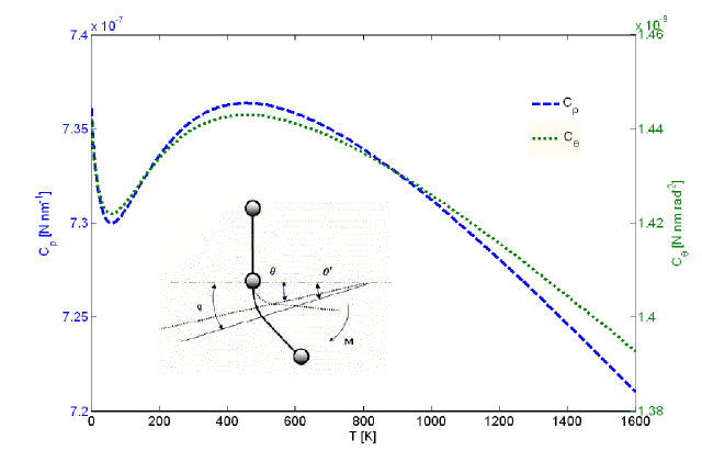
Classical mechanistic theories for the elastic properties of single-wall carbon nanotubes consider the strain energy associated to the deformation of bonds in terms of stretching and bond angle constants ( and respectively Chang T and Gao H (2003); Shen L and Li J (2004)). For the bond angle constant (moment), we consider that for linear elasticity the lattice is dominated by hinging deformation P P Gillis (1984). In cellular structures under general flexural/axial deformations, the hinging constant can be calculated as , where is the portion of the C-C bond length undergoing hinging, while the segment deforms as a rigid body (Masters IG and Evans KE (1996), see also Figure 1). Using the relations (7), the bending angle constant can be rewritten as . Considering a ratio , inserting the numerical values of the thickness and equilibrium length at room temperature we obtain a value of 1.44 , well in line with the 1.42 used in Chang T and Gao H (2003); Shen L and Li J (2004). The stretching constant is calculated as , where to converge to the 0.36 of the in-plane graphitic surface modulus (chiral index ) P P Gillis (1984); Cho J et al. (2007). At room temperature, the stretching constant identified in this model is equal to 735 , which compares well with the 742 used by Shen and Li Shen L and Li J (2004). Cadelano et al Cadelano et al. (2009) have identified a value of the surface modulus of graphene-type systems equal to 0.312 at zero temperature damped dynamics using tight binding calculations and continuum elasticity. Using our approach, we observe a value of 0.332 at zero temperature, 6 % higher. For both the bending and stretching constants, we observe a very low dependence versus the environmental temperature between . The stretching constant then decreases with increasing temperatures with an approximate rate of 0.015 , a behaviour similar to the one of the constant, having the latter a decrease rate of between 600 K and 1600 K. At low temperatures, both the force and bending constants decrease from values equal to 99.2 % of the maximum and at 1 K to a minimum at 70 K corresponding to the 98.6 % of the maximum of the constants at 450 K. Similarly to the C-C bond thickness, the force stretching and bending constants can be expressed in polynomial terms, as illustrated in Table 1.
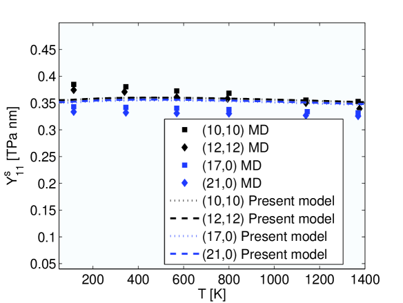
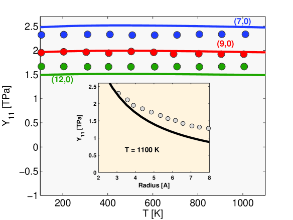
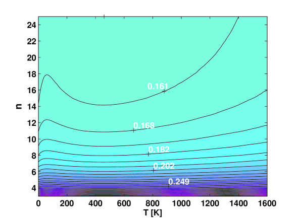
The temperature-dependent constants and can now be used in atomistic-continuum approaches illustrated in open literature to model in a closed-form solution the mechanical properties of SWCNTs under different temperature conditions. In this work we have used the formulation proposed by Shen and Li Shen L and Li J (2004) to simulate the axial and shear stiffness, as well as the Poisson’s ratio of the nanotubes with armchair and zigzag geometry. We compare the surface Young’s modulus calculated in analytical form against the results obtained through MD simulations using a REBO potential by Zhang and Shen Zhang CL and Shen HS (2006) (Figure 2). Our predictions are well in line with the 0.352 of Tu and Ou-Yang Tu Z and Ou-Yang Z (2002) and Pantano et al Pantano et al. (2003), although 3.5 % higher than Li and Chou Li C and Chou TW (2003) and Wang and co-Authors Wang et al. (2005). In terms of longitudinal modulus (defined as ), our predictions tend to overestimate the MD simulations in Zhang CL and Shen HS (2006). For example, our axial moduli for (17,0) nanotubes are 9 % higher than the molecular dynamics simulations at , while a at a temperature of 1000 K our overestimate is around 11 %. The effective Young’s modulus (where is the diameter of the nanotube) has been also derived by Hsieh et al Hsieh JY et al. (2006) from the vibration amplitude of clamped-free nanotubes simulated with a Tersoff-Brenner potential at temperatures ranging between 0 K and 2000 K. The MD simulations in Hsieh JY et al. (2006) are least-squares fitted to an asymptotic value of the graphene Young’s modulus equal to 1.2 TPa found by Hernandez E et al. (1998); Lier G V et al. (2000) at a not specified temperature, 20 % higher than the experimental value found by Lee et al for a thickness of 0.34 nm Lee C et al. (2008). A general comparison of the results from Hsieh JY et al. (2006) against our simulations is presented in Figure 3, showing a general agreement between trends related to the nanotube radius at , and within the temperature range 50 K - 1100 K. We observe a good convergence between MD and our simulations especially for CNT radius lower than 0.5 nm, and excellent agreement (percentage error less than 4 %) for (7,0) SWCNTs over the temperature range considered. Hsieh and co-Authors record a steep decrease in terms of axial stiffness above 1100 K, corresponding to an abrupt change of the standard deviation associated to the dynamic tip displacements of the tube Hsieh JY et al. (2006). We observe also an overestimate for the shear modulus Zhang CL and Shen HS (2006), with discrepancies around 29 % and 28 % at 1000 K and 1200 K respectively. However, our predictions show a decrease of the longitudinal shear modulus versus the temperature, opposite from the results derived in Zhang CL and Shen HS (2006). The transverse Poisson’s ratio increases with the temperature (Figure 4), although the augmentation is limited on average to a 3 % increase between and for the different chirality and tube diameters. The low sensitivity of the Poisson’s ratio over the temperature is due to the weak dependency versus the temperature itself of the term , which is contained both in the numerator and denominator of the Poisson’s ratio expression Shen L and Li J (2004). Chen et al. Chen X et al. (2009) observe also an increase of with temperature (31 % of increase for zizgag tubes of 1.2 nm diameter between room temperature and ). The discrepancy between theirs and our predictions is due mainly to the coefficient of thermal expansion used for the C-C bond, being positive in their case for , while our model has a positive CTE for temperatures higher than 650 K Jiang JW and Wang JS and Li B (2009). We observe that Zhang and Shen predict a transverse Poisson’s ratio for a (17,0) nanotube at equal to 0.17, in good agreement with our value of 0.16 Zhang CL and Shen HS (2006). We note that for graphene-type systems, our model predicts at zero temperature a Poisson’s ratio of 0.12, significantly lower than the 0.31 identified in Cadelano et al. (2009). However, our range of Poisson’s ratios at room temperature for zigzag tubes (Figure 4) is in line with the 0.12 - 0.19 values predicted by Sanchez-Portal et al Sánchez-Portal et al. (1999), the 0.15 of Kudin and co-Authors Kudin K N et al. (2001), 0.21 of Sears and Batra Sears and Batra (2004), and 0.24 from Zhou et al Xin et al. (2000).
In summary, our model allows to predict in a compact form the overall elastic transverse properties of single wall nanotubes over a large temperature range. The bending and stretching constants identified with our approach capture the intrinsic hinging/stretching behaviour of C-C bonds in nanotubes, and relate the stiffness and Poisson’s ratio to the ambient temperature of the nanotube, with 2 % average decrease of the Young’s modulus between the ambient temperature and 1200 K for a given tube chirality.
References
- Zhan, Guo-Dong et al. (2003) Zhan, Guo-Dong, Kuntz, Joshua D., Wan, Julin, and Mukherjee, Amiya K., Nature Materials 1, 38 (2003).
- Biercuk et al. (2002) M. J. Biercuk, M. C. Llaguno, M. Radosavljevic, J. K. Hyun, A. T. Johnson, and J. E. Fischer, Applied Physics Letters 80, 2767 (2002).
- Jianwei Che et al. (2000) Jianwei Che, Tahir Cagin, and William A Goddard III, Nanotechnology 11, 65 (2000).
- J. Hone et al. (2002) J. Hone, M.C. Llaguno, M.J. Biercuk, A.T. Johnson, B. Batlogg, Z. Benes, and J.E. Fischer, Applied Physics A 74, 339 (2002).
- Sun C Q et al. (2003) Sun C Q, Bai H L, Tai B K, Li S, and Jiang E Y, J. Phys. Chem.B 107, 7544 (2003).
- Kwon Y and Berber S and Tomanek D (2004) Kwon Y and Berber S and Tomanek D, Physical Review Letters 92, 01590 (2004).
- Cao G and Chen X and Kysar GW (2006) Cao G and Chen X and Kysar GW, Journal of the Mechanics and Physics of Solids 54, 1206 (2006).
- Wei et al. (2003) C. Wei, K. Cho, and D. Srivastava, Phys. Rev. B 67, 115407 (2003).
- Dumitrica et al. (2006) T. Dumitrica, M. Hua, and B. I. Yakobson, Proceedings of the National Academy of Sciences of the United States of America 103, 6105 (2006), ISSN 00278424.
- Zhang CL and Shen HS (2006) Zhang CL and Shen HS, Applied Physics Letters 89, 081904 (2006).
- Hsieh JY et al. (2006) Hsieh JY, Lu JM, Huang MY, and Hwang CC, Nanotechnology 17, 3920 (2006).
- Liu TT and Wang X (2007) Liu TT and Wang X, Physics Letters A 365, 144 (2007).
- Chen X et al. (2009) Chen X, Wang X, and Liu BY, Journal of Reinforced Plastics and Composites 28, 551 (2009).
- Wei (2006) C. Wei, Applied Physics Letters 88, 093108 (pages 3) (2006).
- Chang T and Gao H (2003) Chang T and Gao H, J. Mech. Phys. Solids 51, 1059 (2003).
- Shen L and Li J (2004) Shen L and Li J, Physical Review B 89, 045414 (2004).
- Rappe A K et al. (1992) Rappe A K, Casewit C J, Colwell K S, Goddard W A, and Skiff W M, Journal of the American Chemical Society 114, 10024 (1992).
- Cornell W D et al. (1995) Cornell W D, Cieplak P, Bayly C I, Gould I R, Merz K M, Ferguson D M, Spellmeyer D C, Fox T, Caldwell J W, and Kollman P A, Journal of American Chemical Society 117, 5179 (1995).
- Li C and Chou TW (2003) Li C and Chou TW, International Journal of Solids and Structures 40, 2487 (2003).
- Odegard et al. (2003) G. M. Odegard, T. S. Gates, K. E. Wise, C. Park, and E. J. Siochi, Composites Science and Technology 63, 1671 (2003), ISSN 0266-3538, modeling and Characterization of Nanostructured Materials.
- Jiang JW and Wang JS and Li B (2009) Jiang JW and Wang JS and Li B, Physical Review B 80, 205429 (2009).
- Bao W et al. (2009) Bao W, Miao F, Chen Z, Zhang H, Jang W, Dames C, and Lau C N, Nature Nanotechnology 4, 562 (2009).
- Tserpes K I and Papanikos P (2005) Tserpes K I and Papanikos P, Composites B 36, 468 (2005).
- Huang Y et al. (2006) Huang Y, Wu J, and Hwang K C, Physical Revue B 74, 245413 (2006).
- Scarpa F and Adhikari S (2008) Scarpa F and Adhikari S, J. Phys. D: App. Phys. 41, 085306 (2008).
- Scarpa F et al. (2009) Scarpa F, Adhikari S, and Phani A S, Nanotechnology 20, 065709 (2009).
- Scarpa F et al. (2010) Scarpa F, Adhikari S, Gil A J, and Remillat C, Nanotechnology 21, 125702 (2010).
- Przemienicki J S (1968) Przemienicki J S, Theory of Matrix Structural Analysis (McGraw-Hill, New York, 1968).
- Kaneko T (1974) Kaneko T, J. Phys. D: App. Phys. 8, 1927 (1974).
- Gibson L J and Ashby M F (1997) Gibson L J and Ashby M F, Cellular Solids: structure and properties (Cambridge Press, 1997), 2nd ed.
- Kudin K N et al. (2001) Kudin K N, Scuseria G E, and Yakobson B I, Phys. Rev. B 64, 235406 (2001).
- Tu Z and Ou-Yang Z (2002) Tu Z and Ou-Yang Z, Phys. Rev. B 65, 233407 (2002).
- Batra RC and Sears A (2007) Batra RC and Sears A, Modelling and Simulation in Materials Science and Engineering 15, 835 (2007).
- Batra RC and Gupta SS (2008) Batra RC and Gupta SS, ASME Journal of Applied Mechanics 75, 061010 (2008).
- X Chen and G Cao (2006) X Chen and G Cao, Nanotechnology 17, 1004 (2006).
- Yakobson et al. (1996) B. I. Yakobson, C. J. Brabec, and J. Bernholc, Phys. Rev. Lett. 76, 2511 (1996).
- Vodenitcharova and Zhang (2003) T. Vodenitcharova and L. C. Zhang, Phys. Rev. B 68, 165401 (2003).
- P P Gillis (1984) P P Gillis, Carbon 22, 387 (1984).
- Masters IG and Evans KE (1996) Masters IG and Evans KE, Composite Structures 35, 403 (1996).
- Cho J et al. (2007) Cho J, Luo J J, and Daniel I M, Comp. Sci. Tech. 67, 2399 (2007).
- Cadelano et al. (2009) E. Cadelano, P. L. Palla, S. Giordano, and L. Colombo, Phys. Rev. Lett. 102, 235502 (2009).
- Pantano et al. (2003) A. Pantano, M. C. Boyce, and D. M. Parks, Phys. Rev. Lett. 91, 145504 (2003).
- Wang et al. (2005) L. Wang, Q. Zheng, J. Z. Liu, and Q. Jiang, Phys. Rev. Lett. 95, 105501 (2005).
- Hernandez E et al. (1998) Hernandez E, Goze C, Bernier P, and Rubio A, Physical Review Letters 80, 4502 (1998).
- Lier G V et al. (2000) Lier G V, Alsenoy C V, Doren V V, and Greelings P, Chem. Phys. Lett. 326, 181 (2000).
- Lee C et al. (2008) Lee C, Wei X, Kysar J W, and Hone J, Science 321, 385 (2008).
- Sánchez-Portal et al. (1999) D. Sánchez-Portal, E. Artacho, J. M. Soler, A. Rubio, and P. Ordejón, Phys. Rev. B 59, 12678 (1999).
- Sears and Batra (2004) A. Sears and R. C. Batra, Phys. Rev. B 69, 235406 (2004).
- Xin et al. (2000) Z. Xin, Z. Jianjun, and O.-Y. Zhong-can, Phys. Rev. B 62, 13692 (2000).
| Quantity | ||||||||||
|---|---|---|---|---|---|---|---|---|---|---|
| X [nm] | ||||||||||
| X | ||||||||||
| X |