OBSERVATION OF CHAOTIC BEATS IN A DRIVEN MEMRISTIVE CHUA’S CIRCUIT
Abstract
In this paper, a time varying resistive circuit realising the action of an active three segment piecewise linear flux controlled memristor is proposed. Using this as the nonlinearity, a driven Chua’s circuit is implemented. The phenomenon of chaotic beats in this circuit is observed for a suitable choice of parameters. The memristor acts as a chaotically time varying resistor (CTVR), switching between a less conductive OFF state and a more conductive ON state. This chaotic switching is governed by the dynamics of the driven Chua’s circuit of which the memristor is an integral part. The occurrence of beats is essentially due to the interaction of the memristor aided self oscillations of the circuit and the external driving sinusoidal forcing. Upon slight tuning/detuning of the frequencies of the memristor switching and that of the external force, constructive and destructive interferences occur leading to revivals and collapses in amplitudes of the circuit variables, which we refer as chaotic beats. Numerical simulations and Multisim modelling as well as statistical analyses have been carried out to observe as well as to understand and verify the mechanism leading to chaotic beats.
Keywords: Driven Chua’s circuit; active memristors; piece-wise linear nonlinearities; chaotically time varying resistors (CTVR); residence times; switching frequencies.
Email: lakshman@cnld.bdu.ac.in
Running Title : Beats in Memristive Driven Chua’s Circuit
Corresponding author : M. Lakshmanan
1 Introduction
The phenomenon of beats arises due to the superposition of two periodic excitations of slightly different frequencies. This superposition results in a cyclic behaviour arising due to the constructive and destructive interferences between these two excitations. The resultant waveform is characterized by a frequency that equals the average of the frequencies of the two waves, whereas its amplitude is modulated by an envelope, whose frequency known as the beat frequency is the difference between the frequencies of the two waves. This phenomenon has been widely studied in linear systems. However recently, attention has been drawn to chaotic and hyper-chaotic beats in nonlinear systems. Chaotic or hyper-chaotic beats arise due to the irregular collapses and revivals in amplitudes of the variables of nonlinear systems as a result of the interaction between two different excitations (either self oscillations or external driving forces) in these systems. Though they can be identified by visual inspection, the presence of positive Lyapunov exponent(s) is considered as the true characterizing feature of chaotic or hyper-chaotic beats. Chaotic and hyper-chaotic beats were identified for the first time in a system of coupled Kerr oscillators and coupled Duffing oscillators with small nonlinearities and strong external pumping [Grygiel Szlachetka, 2002]. Chaotic beats were also reported in coupled non-autonomous Chua’s circuits [Cafagna Grassi, 2004]. Weakly chaotic and hyper-chaotic beats were reported in individual and coupled nonlinear optical subsystems, respectively, describing second harmonic generation (SHG) of light [Śliwa et al., 2008]. In all these coupled systems [Grygiel Szlachetka, 2002; Cafagna Grassi, 2004; Śliwa et al., 2008], the occurrence of beats is attributed to the interaction between the self oscillations or driven oscillations of each of the coupled subsystems. Using extensive Pspice simulations, the occurrence of beats in individual driven Chua’s circuit with two external excitations has also been reported [Cafagna Grassi, 2006a; 2006b]. Chaotic beats have also been found to occur in individual Murali- Lakshmanan-Chua (MLC) circuit by the same authors [Cafagna Grassi, 2005]. In these cases of single systems [Cafagna Grassi, 2005; 2006a; 2006b], two different external driving forces with slightly differing frequencies were the cause for the occurrence of beats.
On the other hand, from a different perspective, Leon Chua in the year 1971 introduced a fourth circuit element, namely the memristor [Chua, 1971; Chua Kang, 1976], purely from theoretical arguments, and pointed out the interesting possibilities of including it in electronic circuits. Almost four decades later, Strutkov et al. of Hewlett-Packard Laboratories designed the first approximate physical example of a memristor [Strutkov, 2008] in a solid-state nano-scale system in which electronic and ionic transports are coupled under an external bias voltage. As the characteristic of memristors is inherently non-linear and is unique in the sense that no combination of nonlinear resistive, capacitive and inductive components can duplicate their circuit properties, memristors have generated considerable excitement among circuit theorists. Further they provide new circuit functions such as electronic resistance switching at extremely high two-terminal device densities [Strutkov, 2008]. Very recently Itoh and Chua [2009], have investigated the dynamics of nonlinear electronic circuits of different orders, including autonomous Chua’s oscillator and canonical Chua’s oscillator by replacing a Chua’s diode - a well studied and familiar nonlinear device - by an active or a passive memristor. Hence it will be of high current interest to study the effect of replacing the Chua’s diode by a memristor in a driven Chua’s circuit [Murali Lakshmanan, 1990; 1991], and investigate the new dynamical phenomena which arise from the corresponding circuit.
In the present paper, we report the occurrence of chaotic beats in the driven Chua’s circuit using a flux controlled active memristor as its nonlinearity. The importance of this circuit is that it employs just a single driving force and makes use of the chaotically time varying resistive property and the switching characteristic of the memristor to generate beats. The plan of the paper is as follows. In Sec. 2 memristors, their characteristic and their behaviours are briefly described. In Sec. 3.1 the standard driven Chua’s circuit is introduced while in Sec. 3.2 the driven Chua’s circuit using a memristor as the nonlinear element is described. In Sec. 4 the chaotic beats phenomenon observed numerically in this circuit is shown with the aid of time series plots, phase portraits and Poincaré maps, Lyapunov exponents and power spectral calculations. In Sec. 5 an experimentally realisable circuit for the memristor is proposed. Using Multisim modelling, a driven Chua’s circuit is constructed and the chaotic beats observed. With the help of the grapher facility of the software package, time series plots, phase portrait, power spectra which are qualitatively equivalent to the numerical observations are presented. In Sec. 6 the mechanism for the occurrence of chaotic beats is discussed, while Sec. 7 presents a brief conclusion.
2 Memristors
From a circuit theoretic point of view, Leon Chua [1971] noted that there could possibly be six mathematical relations connecting pairs of the four fundamental variables, namely charge , current , flux and voltage . One of these relations (the charge is time integral of current) is determined from the definitions of the two variables. Another relation (the flux is the time integral of the electromotive force or voltage) is given by Faraday’s law of induction. Three other relations can be constructed from the axiomatic definitions of the three classical two terminal circuit elements, namely, the resistor (defined by the relationship between and ), the inductor (defined by the relationship between and ) and the capacitor (defined by the relationship between and). One more relationship between and remains undefined. From logical and axiomatic points of view, as well as for the sake of completeness, the necessity for the existence of a fourth basic two terminal circuit element was postulated by Chua [1971]. This missing element purported to have a functional relationship connecting charge and flux is named as . This hypothetical element is endowed with both a resistive property and a memory like nature and hence it is named so. In principle, memristors with almost any characteristic can be synthesised [Chua, 1971]. Although realized, albeit only recently, and that too in the nano-scale range, memristors have been successfully used as a conceptual tool for analysis in signal processing and nonlinear circuits, see for example [Tour He, 2008]. In particular their nonlinear characteristic provides designers with new circuit functions like electronic resistance switching at extremely high two terminal densities [Strutkov et al., 2008].
3 Dynamics of the Driven Memristive Chua’s Circuit
We will now study the dynamics of the driven memristive Chua’s circuit to bring out the concept of chaotic beats in it. For this purpose we shall first introduce the standard driven Chua’s circuit.
3.1 Driven Chua’s Circuit
The driven Chua’s circuit is a fourth order non-autonomous circuit first introduced by Murali and Lakshmanan in the year 1990 [Murali Lakshmanan, 1990]. It is found to exhibit a large variety of bifurcations such as period adding, quasi-periodicity, intermittency, equal periodic bifurcations, re-emergence of double hook and double scroll attractors, hysteresis and coexistence of multiple attractors, besides the standard bifurcations . Its dynamics in the environment of a sinusoidal excitation has been extensively studied in a series of works [Murali Lakshmanan, 1990; 1991; 1992a; 1992b; 1993]. Due to its simplicity and the rich content of nonlinear dynamical phenomena, the driven Chua’s circuit continues to evoke renewed interest by researchers in the field of non-linear electronics [Anishchenko et al., 1993; Zhu Liu 1997; Elwakil 2002; Srinivasan et al., 2009].
3.2 Driven Memristive Chua’s Circuit
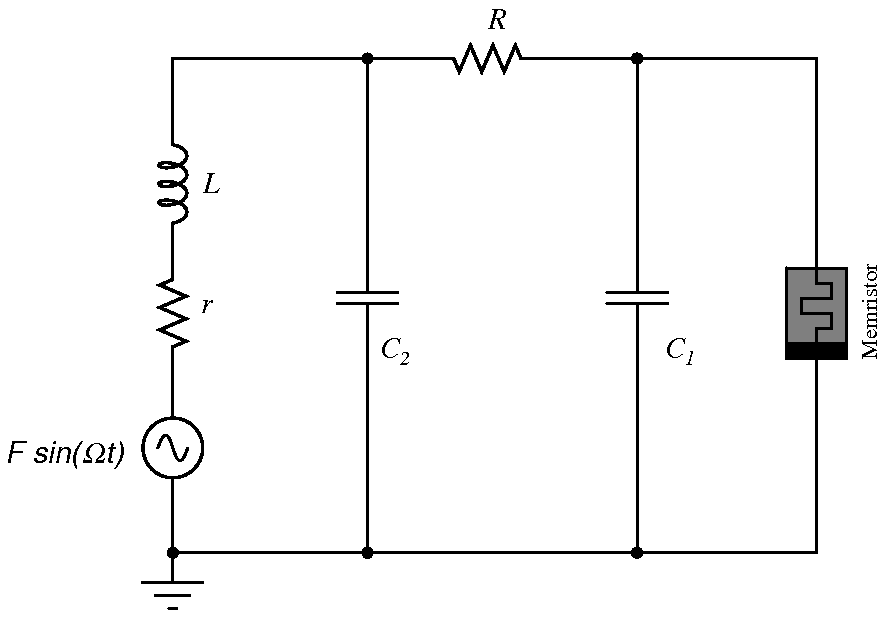
A large number of autonomous nonlinear electronic circuits using memristors as active nonlinear elements have been studied very recently by Itoh and Leon Chua [Itoh Chua, 2008] and the conditions for the occurrence of chaos in them were mathematically analysed and numerically simulated. Muthuswamy has proposed a memristor having a cubic nonlinearity [Muthuswamy, 2009a; 2009b]. Using it a simple three element autonomous Chua’s circuit was designed and its chaotic behaviour studied using MATLAB simulations, and also real time experiments. In this paper, we modify the driven Chua’s circuit [Murali Lakshmanan, 1990] mentioned above by removing an inductance and replacing the Chua’s diode with a three segment piecewise-linear flux controlled active memristor [Itoh Chua, 2008] as its nonlinearity. The circuit is given in Fig. 1.
An active flux controlled memristor has the charge through it as some function of the flux across it. The functional relationship between the flux and charge is assumed to be the same expression as given in [Itoh Chua, 2008], namely
| (1) |
where a and b are the slopes in the inner and outer segments of the characteristic curve and is a negative conductance which is connected in parallel to the flux controlled memristor to make it satisfy the condition for activity.
The memristor employed here is an active device in the sense that it does not draw power from the circuit of which it is a part of, but in fact it supplies power to it. It satisfies the criterion for activity [Chua, 1971], namely
| (2) |
where is the instantaneous power dissipated across the memristor and is the memductance of the memristor. The latter is so called because it has the units of conductance . It is given by
| (3) |
where are as defined earlier.
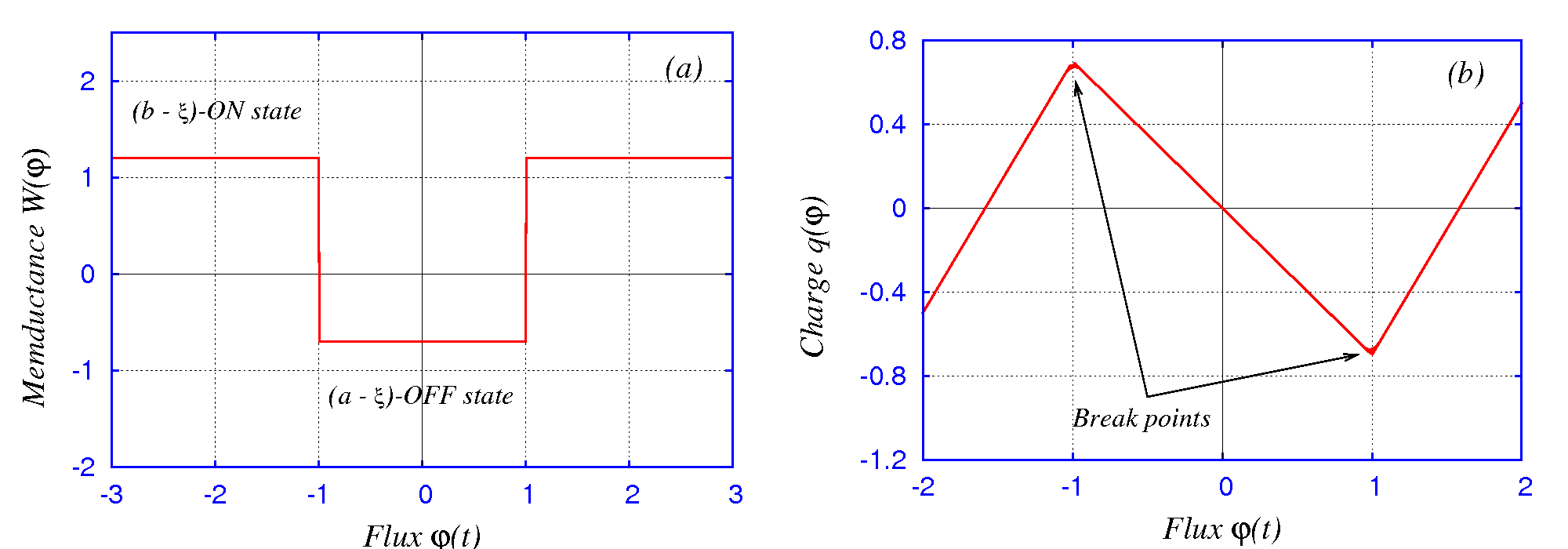
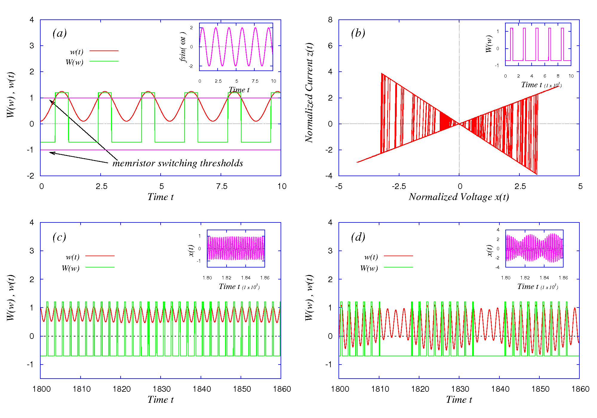
The memductance of the memristor takes on two particular values as shown in Fig. 2(a), depending on the value of the flux across it. The higher memductance value can be referred as the ON state and the lesser memductance value can be referred as the OFF state. Obviously, as the flux across the memristor changes, the memristor switches or toggles between these two states. This switching action can be made use of profitably in utilising the memristor as a desirable element in modelling of nonlinear circuits. The characteristic curve in the plane which causes this memristive switching is shown in Fig. 2(b).
Following Itoh Chua [2008], the circuit equations for the memristive driven Chua’s circuit given by Fig. 1, are written as
| (4) |
Normalizing equations (4) using the same rescaling parameters as those used in [Itoh Chua, 2008], namely
| (5) |
we have
| (6) |
Here dot stands for differentiation with respect to t.
The piecewise linear function describing the memristor then becomes
| (7) |
where are now the normalized values of the quantities mentioned earlier.
4 Observation of Chaotic Beats (Numerical Analysis)
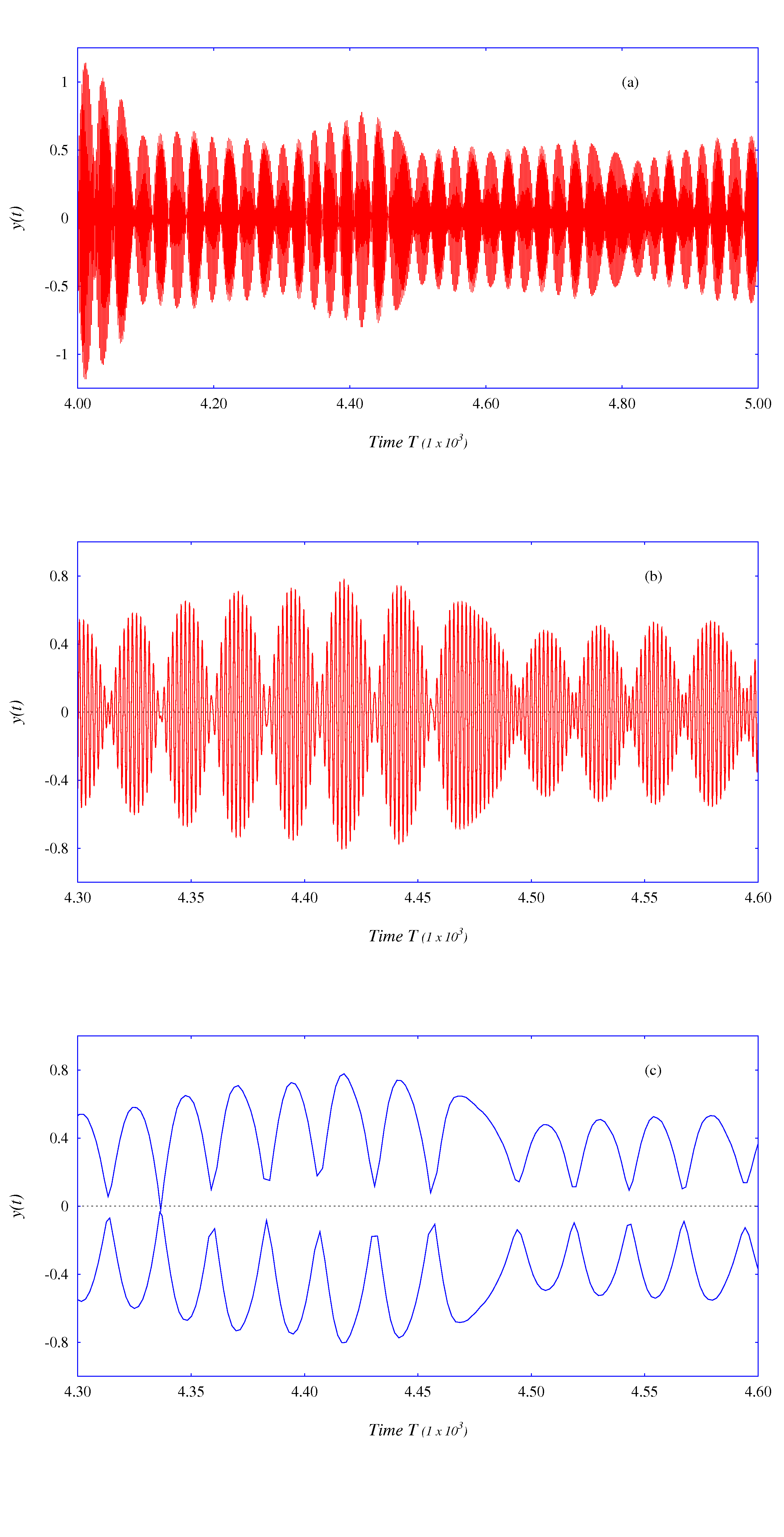
The above circuit, represented by the normalized equations (6), though simple in nature, generates beats due to the slight tuning / detuning of frequencies of the external driving excitation and the switching of the memristor between the ON and OFF memristive states. If we set and change the force and frequency of the external signal suitably in equations (6), chaotic beats are found to occur in this circuit. For example for and , chaotic beats are observed. This can be seen clearly in Figs. 3. While Fig. 3(a) shows a sampled stretch of the time series for the variable depicting chaotic modulation in amplitudes, Fig. 3(b) shows an enlarged portion of the same illustrating the presence of a central fundamental frequency component, which we call as . In Fig. 3(c), the envelope of the amplitudes of the same variable for the same stretch as in Fig. 3(b), isolated by Poincaré mapping technique, is captured. It shows that this variation of the amplitudes occurs at a smaller frequency, which we will call as .
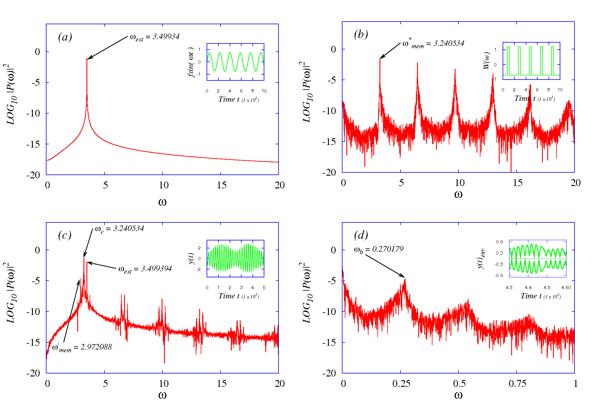
To find the frequencies of the circuit variables as well as to determine the frequency with which the memristor changes its ON memductive state to OFF state and vice versa, the power spectra are obtained as shown in Figs. 4, for four different cases, namely (i) for the external driving sinusoidal signal, (ii) for the memristor switching when driven by the self oscillations of the circuit, (iii) for the normalized voltage of the driven Memristive Chua’s oscillator and (iv) for the envelope of the chaotically modulated signal. The various signals whose power spectra are obtained are shown as insets in Figs. 4.
The power spectrum in Fig. 4(a), is that of the sinusoidal forcing. Evidently it shows a single peak corresponding to the driving frequency . The Chua’s circuit, by virtue of being a nonlinear oscillatory circuit, generates chaotic self oscillations at a frequency determined by the dynamics of the circuit, even in the absence of a driving force. Hence the power spectrum of the memristor switching, seen in Fig. 4(b), shows a broad band spectrum with a fundamental frequency component. It is this fundamental frequency that determines the switching of the memristor between its memductive states and is identified as the characteristic memristor frequency, . When an external driving force is added, the dynamics of the circuit changes as result of the interaction of the self oscillations and the driving signal. As is expected this interaction results in some sort of control or suppression of chaos that causes the memristor to lower its switching frequency to a value less than its characteristic frequency. This altered memristor frequency component which we call as the new memristor frequency has been identified from the power spectrum in Fig. 4(c) as . Also the driving frequency is identified from the power spectrum as as it has to be. The central frequency of the chaotically modulated signal is obviously the average of the memristor and external driving frequencies, namely . From the Fig. 4(c), this central frequency is identified as . The power spectrum of the envelope of the chaotically modulated y(t)-variable is shown in Fig. 4(d). The frequency of this envelope is often called as the beat frequency. For a damped forced oscillator system, it is half the difference between the two frequencies involved, namely the new memristor and external frequencies, that is .
To confirm the chaotic amplitude modulation, the Lyapunov exponents of the system are obtained using the well known Wolf algorithm [Wolf etal., 1985]. For a forcing amplitude and forcing frequency , chaotic beats are observed with Lyapunov exponents . It is to be noted that the Lyapunov values obtained in this case are much less than that obtained for an autonomous Chua’s circuit using a memristor [Itoh Chua, 2008], or for a highly frequency detuned driven memristor Chua’s circuit wherein beats phenomenon does not arise at all due to the large frequency mismatch. This lowering of Lyapunov exponents denotes a drop in chaoticity of the circuit. This is because of the control of chaos effected by the introduction of the external driving force on the autonomous Chua’s circuit. These values, though small, agree well with the Lyapunov exponents obtained in earlier works on Chua’s circuits employing ordinary Chua’s diode, namely the two coupled autonomous Chua’s circuit [Cafagna Grassi, 2004] as well as the driven Chua’s circuit [Cafagna Grassi, 2006a; 2006b] wherein chaotic modulation were observed. While two driving periodic forces were employed to generate beats in the individual circuits, the natural autonomous oscillations of the subsystems of the two coupled autonomous Chua’s circuit were used to obtain the same for the latter case. It is pertinent to note here that the present circuit is a single four dimensional non-autonomous circuit (a dimension of two less than the six dimensional non-autonomous coupled Chua’s circuit) and generates chaotic beats using a single periodic driving force (unlike two driving forces employed in earlier works). Further the number of dimensionless parameters that tune the behaviour are also less.
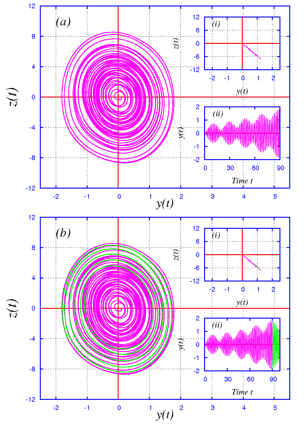
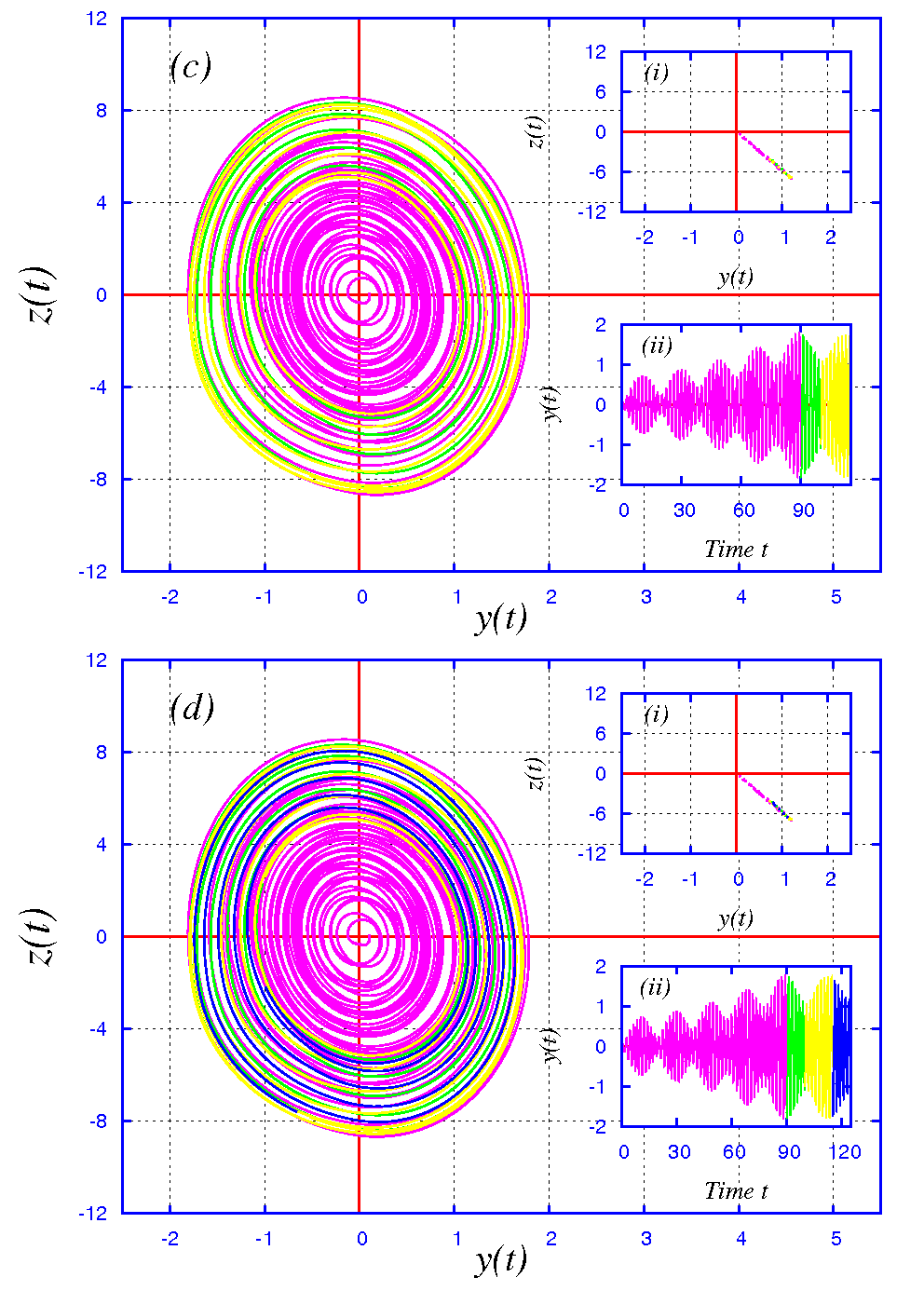
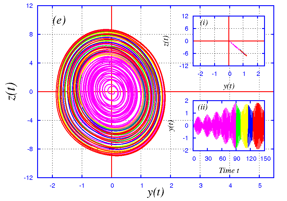
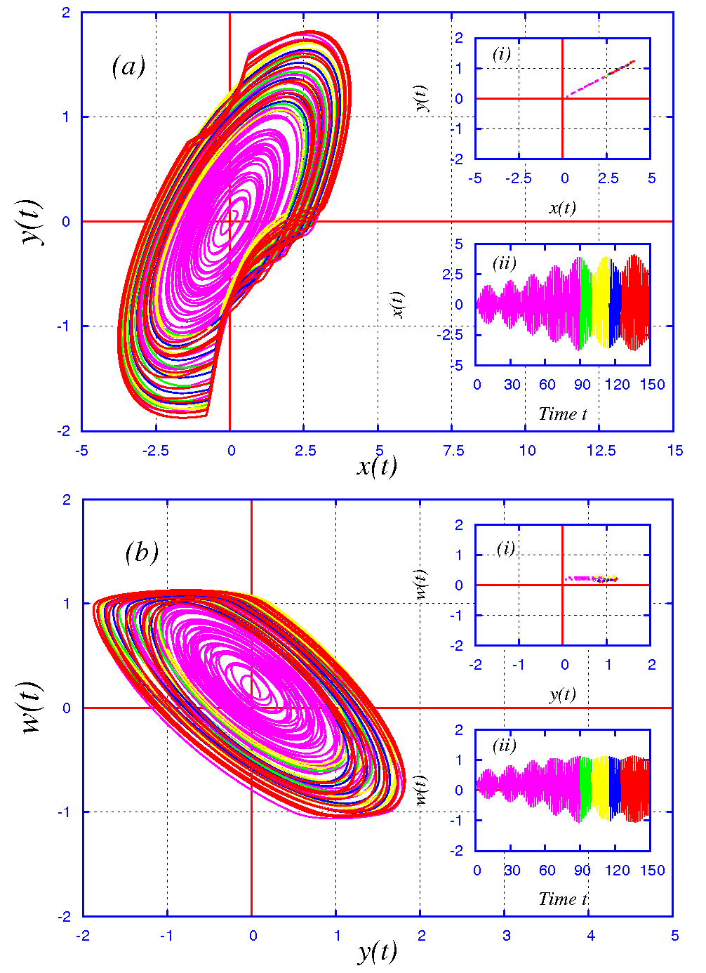
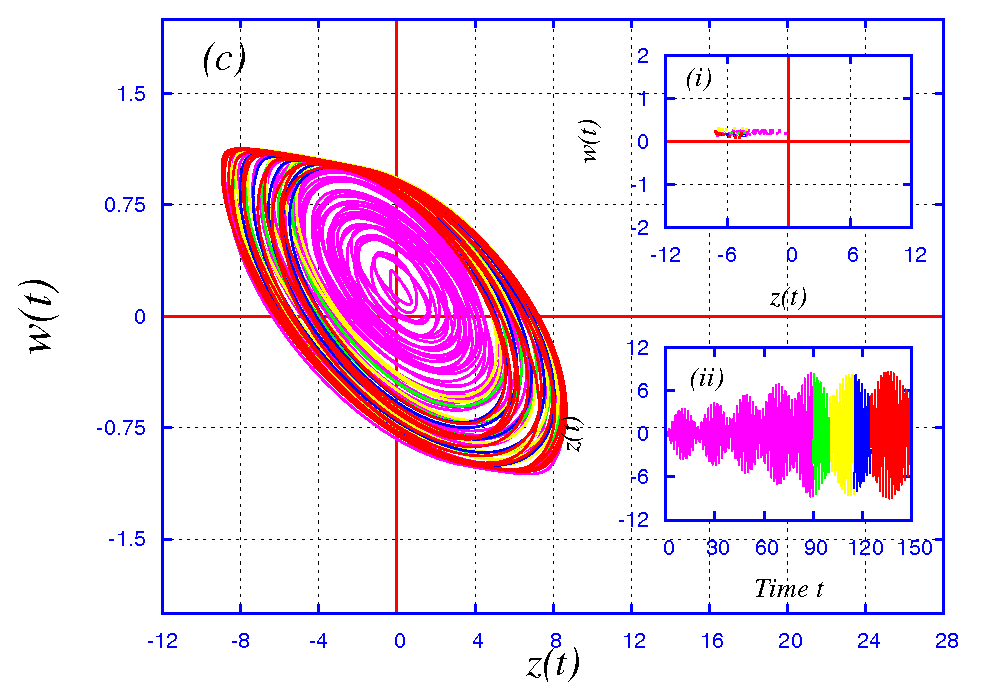
The phase portraits taken for different time durations of evolution show clearly the growth and the shrinkage in the amplitudes or the revivals and collapses of the system variables as the dynamics evolves, resulting in the occurrence of beats. In Figs. 5, one finds the successive expansions and contractions of the attractor in the phase plane as time elapses. In Figs. 6, the corresponding variations in the attractor amplitudes in the , and phase planes are shown. The Poincaré maps and the time series plots are shown as insets (i) and (ii) in the respective phase portraits. In all of these cases, the state variables expand up to 90 time units and then undergo a shrinkage up to 100 time units. They undergo a further growth and decay in amplitudes for successive intervals of time. This process of growth and decay in amplitudes continues adinfinitum and is governed by the dynamics of the system.

5 Experimental Investigations
Next, in this section, we will present our study on the experimental confirmation of the above numerical results through Multisim modelling. A memristor having a smooth nonlinear third order polynomial relationship between flux and charge has been designed by Muthuswamy [2009b]. This is based on the cubic nonlinear resistive circuit designed by Zhong [1994]. However in this paper, we propose a circuit model for a three segment piecewise flux controlled active memristor. A memristor is a device whose resistive or conductive state depends on the magnitude of flux across it. By Faraday’s law, the flux passing through a memristor is the time integral of the electromotive force across it,
| (8) |
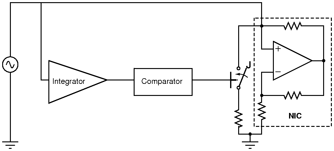
Using this simple logic, an analog electronic implementation of the memristor can be designed. The block diagram illustrating this principle is given in Fig. 7(a). This model is based the time varying resistor (TVR) circuit proposed by Nishio et al. [1993]. Here a linear resistance and a negative impedance converter (NIC) are switched ON and OFF alternatively based on the output pulse of a comparator.The comparator compares the flux through the memristor ( that is the integral of the voltage across the memristor) between two reference levels, called breakdown points. For flux values lying within the upper and lower breakdown points ( namely flux units ) the negative conductance is included in the circuit. For flux values exceeding the breakdown points, the resultant of the linear resistance and negative conductance, which are in parallel, is included in the circuit. The flux is obtained by an integrator circuit. By this action, the functional relationship between the flux and charge given in equation (1) is realized.


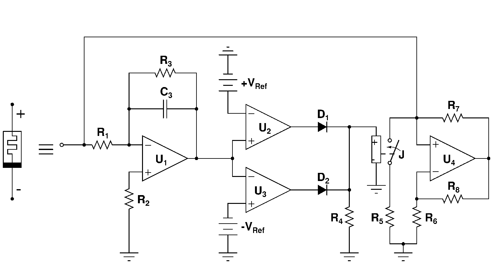
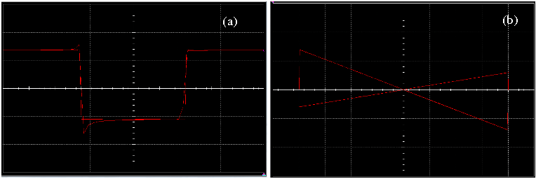
This proposed circuit is implemented using Multisim modelling and is given in Fig. 7(b). The values of the linear resistances are and . The values of the other parameters are: .For the Multisim switch module, the ON state resistance is set as and the OFF state resistance is chosen as and the threshold voltage is set as . When an external sinusoidal source is applied, the flux across the memristor changes, causing the memductance state to switch between a low OFF state and a high ON state as shown in Fig. 8(a). The flux is obtained as the output of the integrator circuit and the divider module facility of Multisim. If the inputs to the divider module are the voltages and currents across the memristor, then an inverse measure of the memductance can be obtained. The characteristic of the memristor in the plane is shown in Fig. 8(b). It is clearly a pinched hysterectic curve, wherein the currents fall to zero whenever the voltage across the memristor becomes zero. This is a characteristic feature of the memristors.
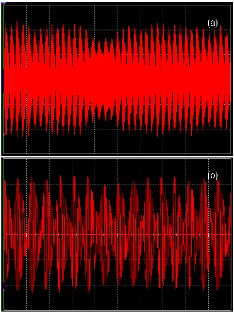
The driven Chua’s circuit is investigated by using Multisim model of the memristor proposed. The circuit implementation is shown in Fig. 9. The parameter values of the circuit are fixed as . For the memristive part, the parameters are as given earlier. Here, for the sake of experimental convenience, the parameters chosen are slightly different from those of numerical values. Yet the observed behaviours are found to be qualitatively same to those obtained through numerical simulations. For this choice of parameters, chaotic beats are observed when the forcing amplitude is varied keeping the frequency of the external forcing a constant or vice versa. The time series of the voltage across the capacitor showing chaotic variations in amplitude is given in Fig. 10(a). An extended region of the same is given in Fig. 10(b). The phase portrait in the is shown in Fig. 11. To obtain these, the frequency of the external sinusoidal forcing is fixed as and the amplitude is fixed as . The power spectrum of the variable and that of voltage across the memristor are shown in Figs. 12(a b) respectively. From these the external frequency, the memristor frequency and the central frequency are identified as , and . Note that, this central frequency , as expected.
6 Mechanism of Chaotic Beats in the Driven Memristive Chua’s Circuit
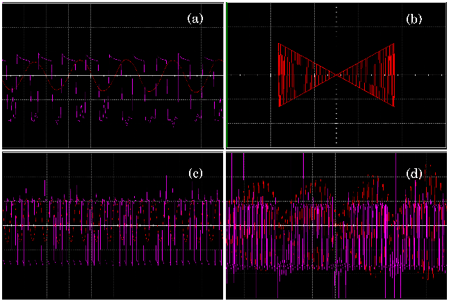
The mechanism for the generation of beats is obviously the switching of the memristor. Essentially a memristor is a device that works under alternating current (a.c) conditions wherein the applied voltage varies sinusoidally with time. As the polarity of this voltage changes sinusoidally with time, the flux across the memristor also changes, causing it to switch reversibly between a less conductive OFF state (low memductance) and a more conductive ON state (high memductance) [Tour He, 2008]. This is shown in Fig. 13(a). The lower memductance level is the OFF state and the higher level is the ON state. The characteristic of the memristor (in the normalized variables) shown in Fig.13(b), makes one perceive vividly the transitions between the bi-stable memductive states. The memristor just acts as a linear time varying resistor (LTVR), see for example[Chua et al., 1987; Nishio Mori, 1993]. This switching of the memristor takes place at a characteristic time period or frequency. However when the memristor is driven by chaotic signals, either through a self oscillatory mechanism or through an external generator of chaotic signals, it switches chaotically between its memductive states. The memristor now acts as a chaotically time varying resistor (CTVR). This chaotic switching is shown in Figs. 13(c) 13(d), where the memristor is driven by voltage across the capacitance of the autonomous Chua’s circuit or the driven Chua’s circuit, for both of which it is an integral part as their nonlinear element. The switching of the memristor observed from Multisim model are qualitative equivalent to Figs 13(a-d) and are shown in Figs. 14(a-d). The unwanted glitches seen in Figs. 14(a d), arise due to the mismatch in the delay times of the circuit components.
From the normalized Eqs.(6) (7), for the amplitude of the driving force , the equilibrium state of the system is given by
| (9) |
which corresponds to the -axis. The Jacobian matrix at this equilibrium state is given by
| (10) |
Then the characteristic equation is
| (11) |
where the ’s, are various coefficients and ’s are the eigenvalues. Equation (10) can be factorized as
| (12) |
Then the natural frequency of the autonomous circuit for is evaluated by the relation
| (13) |
| (14) |
Numerically, from Eqs. (13) -(14), the frequency of the autonomous circuit is found to vary between and , depending on the values of , and .
The breakpoints in the characterisitc of the memristor shown in Fig. 2(b), namely flux units, can be considered as the memristor switching thresholds. When the flux across the memristor exceeds these threshold values, switching of the memristor between its memductive ON and OFF states occurs. Let and refer to the durations of time the memristor resides in the ON state and OFF state, before switching, respectively. Then the total time taken by the memristor to complete one full switching process is . The switching frequency of the memristor is then 2 times the reciprocal of this total switching time. If the memristor switching frequency is equal to that of the external driving frequency , then the memristor switching operation is said to be or . If it is double or multiples of the external frequency, then the memristor switching operation is said to be .
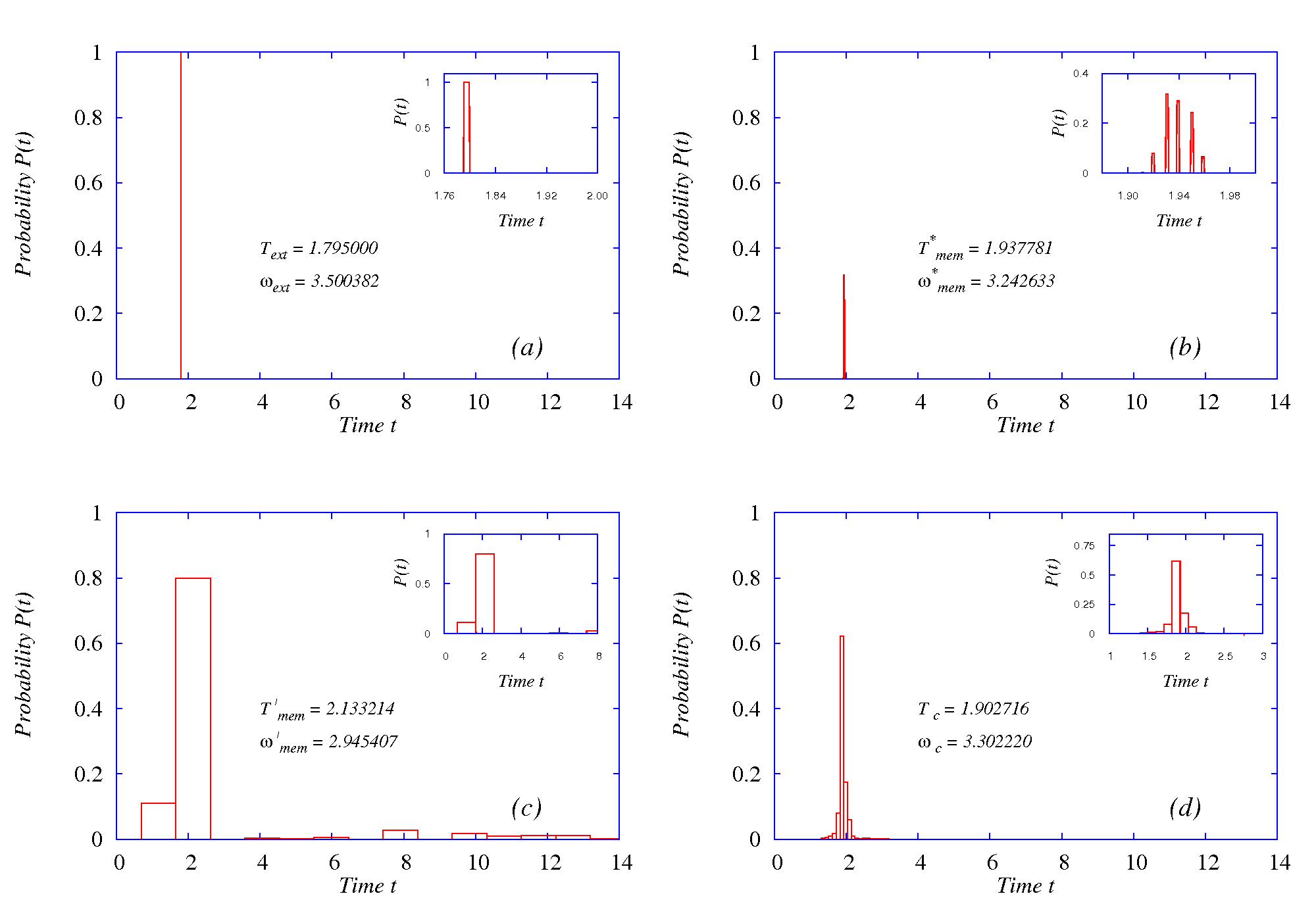
Let us consider a linear sinusoidal excitation of frequency is applied to the memristor. If the flux across the memristor arising due to this sinusoidal excitation were to exceed the two switching thresholds, flux units, then for each external driving cycle, the memristor completes two full switching cycles. The memristor operation will then be subharmonic with a frequency equal to twice the external driving frequency, that is . However, in the present case the flux across the memristor is the time integral of the voltage across it, that is, . This cosinusoidal variation of flux causes it to exceed only one of the two memristor switching thresholds, namely +1 flux unit. Consequently only one memristor switching occurs for each cycle of the sinusoidal forcing. Hence the memristor switching operation is synchronous. If we plot the probability of the switching times of the memristor driven by this linear sinusoidal forcing, we find a single probability peak which corresponds closely to the period of the linear excitation, namely . This translates to a frequency of . This is shown in Fig. 15(a). If the memristor is connected in parallel to the capacitance of the autonomous Chua’s circuit, the memristor gets driven by the self oscillatory combination of the circuit, with a frequency varying from and . The switching of the memristor, because of the inherent chaotic nature of self oscillations of the autonomous circuit, becomes haphazard proving that the memristor now acts as a chaotically time varying resistor CTVR. We get a number of closely spaced switching time probability peaks as shown in Fig. 15(b). The weighted average of these probability peaks gives a switching time which translates to a switching frequency of .
When an external driving force of a frequency, let us say , is added to the circuit, the memristor is driven by the forced oscillations of the circuit. As the forced oscillations are also chaotic, the memristor switching is also necessarily chaotic. Hence it still acts as a CTVR. The probability graph of the memristor switching times shown in Fig. 15(c) now shows a prominent peak at a switching time which corresponds to a memristor switching frequency of . This is the new switching frequency that the memristor takes on as a result of the apparent control of chaos effected in the circuit by the introduction of the external force. At these particular frequencies, and , the external excitations and memristive switching aided forced oscillations in the circuit undergo constructive and destructive interferences, resulting in the modulation of amplitudes and frequencies which we call beats. Varying the external frequency away from this chosen value disrupts the interferences causing the modulation phenomenon to wane and eventually disappear. The average of the external driving frequency and the new memristor frequency gives the central frequency of modulated signal. If we plot the switching time probabilities for the positive and negative cycle variations of the variable under amplitude modulation, we get a prominent probability peak at a switching time . This corresponds to the central frequency . These are shown in Fig. 15(d). The beat frequency, calculated as half the difference in the above said two frequencies, is . The central and beat frequencies obtained from power spectral calculations as well as from probabilistic considerations are shown in Table.1. Both of these agree well qualitatively with the theoretical results. However the small differences in their numerical values may be explained as due to the chaotic nature of the system as well as the large number of frequencies involved.
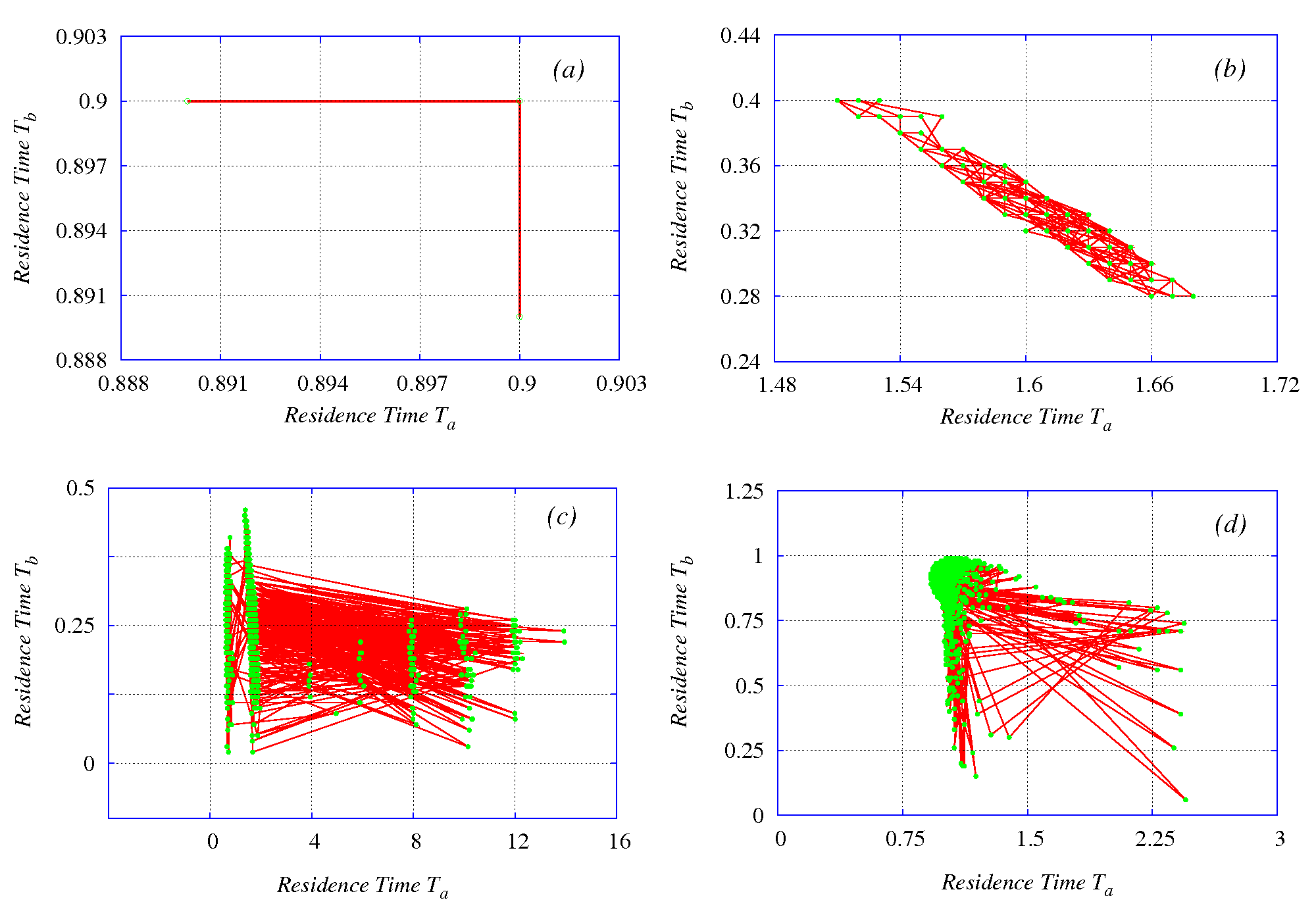
The two dimensional residence time plots for the memristor for the ON and OFF memductive states are plotted in Fig. 16. When a linear force is driving the memristor, the switching (between positive and negative half cycles of the sinusoidal force) is regular as seen in Fig. 16(a). In this case there are only two different values for and . When the oscillatory part of the autonomous Chua’s circuit drives it, because of the inherent chaotic nature of the circuit, the memristor also switches irregularly. The scatter plot of residence times and is erratic and random. This is evident in Fig. 16(b). When a driving force is added, both the external oscillations and the driven oscillations of the circuit interact with each other. In this interaction a control of chaos in the circuit is effected by the external driving force. As the chaoticity is reduced, the circuit tends to approach a regular behaviour, resulting in the occurrence of beats. However as the dynamics of the circuit is still chaotic, the plot of the memristor switching times is also still chaotic, but with a lesser degree of chaoticity or irregularity. This is also the reason for the low values of the Lyapunov exponents obtained. This weak chaotic switching is illustrated in Fig. 16(c). The scatter plot of the switching times (between positive and the negative cyclic variations) of the variable of the system is shown in Fig. 16(d).
7 Conclusion
In this paper the presence of chaotic beats phenomenon in a driven memristive Chua’s circuit is reported. This phenomenon has been observed and verified using numerical simulations in the form of time series plots, phase portraits and Poincaré maps. The chaotic nature of the modulation in amplitudes has been characterized with power spectral density calculations and Lyapunov exponents. Using Multisim modelling an analog electronic circuit to realise the action of a three segment flux controlled memristor is proposed, and the presence of chaotic beats in the driven memristor Chua’s circuit using this memristor has been verified. Further, based on probabilistic considerations, the mechanism for the occurrence of beats has been found to be the interaction due to the dynamics based chaotic time varying resistive property and chaotic switching of the memristor between different memristive states. The use of memristor in the driven Chua’s circuit has enhanced its dynamics considerably. Many features like reverse period doubling route, intermittent route and higher dimensional torus break down route to chaos, hyper chaos, period adding and Farey sequences, transient chaos, double hook attractors etc., can also be identified in this circuit. Much progress has been made along these lines and the results will be published seperately.
8 Acknowledgement
This work forms a part of a Department of Science and Technology (DST), Government of India, IRHPA project of ML and a DST Ramanna Fellowship awarded to him. A.I acknowledges gratefully the University Grants Comission (UGC) of the Government of India for supporting his work under a FDP fellowship (F.ETFTNBD011 FDP/UGC-SERO).
References
-
Anishchenko, V. S., Safonova,M.A. Chua,L.O.[1993] “Stochastic resonance in the nonautonomous Chua’s circuit,” J. Cir. Syst. Comput. 3, 553-578.
-
Cafagna, D. Grassi, G. [2004] “A new phenomenon in nonautonomous Chua’s circuits: Generation of chaotic beats,” Int. J. Bifurcation and Chaos 14, 1773-1788.
-
Cafagna, D. Grassi, G. [2005] “On the generation of chaotic beats in simple nonautonomous circuits,” Int. J. Bifurcation and Chaos 15, 2247-2256.
-
Cafagna, D. Grassi, G. [2006a] “Generation of chaotic beats in a modified Chua’s circuit Part -I: Dynamic Behaviour,” Nonlinear Dynamics 44, 91-99
-
Cafagna, D. Grassi, G. [2006b] “Generation of chaotic beats in a modified Chua’s circuit Part -II: Dynamic Behaviour,” Nonlinear Dynamics 44, 101-108
-
Chua, L.O. [1971] “Memristor- The missing circuit element,” IEEE Trans. Circuit Th. CT- V 18, 507-519.
-
Chua, L. O., Kang, S. M. [1976] “Memristive devices and systems,” Proc. IEEE 64, 209–223.
-
Chua, L.O., Desoer, C. A. Kuh, E. S. [1987] Linear and Nonlinear Circuits (McGraw-Hill Book Company, Singapore) Chap. 2,pp. 59-61.
-
Elwakil, A. S. [2002] “Nonautonomous pulse-driven chaotic oscillator based on Chua’s circuit,” Microelectron.J 33, 479-486.
-
Grygiel, K. Szlachetka, P. [2002] “Generation of chaotic beats,” Int. J. Bifurcation and Chaos 12, 635-644.
-
Itoh, M. Chua, L. O. [2008] “Memristor oscillators,” Int. J. Bifurcation and Chaos 18, 3183-3206.
-
Liu, Z. [2001] “Strange nonchaotic attractors from periodically excited Chua’s circuit,” Int. J. Bifurcation and Chaos 11, 225-230.
-
Murali, K. Lakshmanan, M. [1990] “Observation of many bifurcation sequences in a driven piecewise-linear Circuit,” Phys. Lett. A 151, 412-419.
-
Murali, K. Lakshmanan, M. [1991] “Bifurcation and chaos of the sinusoidally-driven Chua’s circuit,” Int. J. Bifurcation and Chaos 1, 369-384.
-
Murali, K. Lakshmanan, M. [1992a] “Transition from quasiperiodicity to chaos and devil’s staircase structures of the driven Chua’s circuit,” Int. J. Bifurcation and Chaos 2, 621-632.
-
Murali, K. Lakshmanan, M. [1992b] “Effect of sinusoidal excitation on the Chua’s circuit,”IEEE Trans. Circuits & Syst.-1 39, 264-270.
-
Murali, K. Lakshmanan, M. [1993] “Chaotic dynamics of the driven Chua’s circuit,” IEEE Trans. Circuits Syst.-1 40, 836-840.
-
Muthuswamy, B.[2009a] “Memristor based chaotic circuits,” Technical Report No. UCB/EECS- 2009-6 http://www.eecs.berkely.edu/Pubs/TechRpts/2009/EECS-2009-6.html
-
Muthuswamy, B.[2009b] “Implementing Memristor based chaotic circuits,”to be published in Int. J. Bifurcation and Chaos.
-
Nishio, Y. Mori, S. [1993] “Chaotic phenomena in nonlinear circuits with time-varying resistors,” IEICE Trans. Fundamentals E-76A 3, 467-475.
-
Śliwa, I., Grygiel, K. Szlachetka, P.[2008] “Hyperchaotic beats and their collapse to the quasiperiodic oscillations,” Nonlinear Dynamics 53, 13-18.
-
Strutkov, D.B., Snider, G.S., Stewart, D.R. Williams, R.S. [2008] “The missing memristor found,” Nature 453, 80-83
-
Srinivasan, K., Thamilmaran, K. Venkatesan, A. [2009] “Classification of bifurcation and chaos in Chua’s circuit with effect of different periodic forces,” Int. J. Bifurcation and Chaos 19, 1951-1973.
-
Tour, J. M. Tao He. [2008] “The fourth element,” Nature 453, 42.
-
Wolf, A., Swift,J.B., Swinney, H.L. Vastano, J.A. [1985] “Determination of Lyapunov exponents from a time series,” Physica 16D, 285-317.
-
Zhong, G. [1994] “Implementation of Chua’s Circuit with a Cubic Nonlinearity,” IEEE Transactions on Circuits and Systems 41(12), pp. 934-941.
-
Zhu, Z. Liu, Z. [1997] “Strange nonchaotic attractors of Chua’s circuit with quasiperiodic excitation,” Int. J. Bifurcation and Chaos 7, 227-238.
Table
Comparison of frequencies obtained from power spectral and switching time probability calculations from numerical analysis. Frequencies Spectral density calculation Probabilistic consideration External driving frequency 3.499394 3.503184 Memristor switching frequency 3.240534 3.242463 Memristor switching frequency 2.972088 2.945407 Central frequency of the modulated signal 3.240534 3.302220 Beat frequency 0.270179 0.280360
-
The -variable was considered for taking the power spectrum. A total of 65,536 data points at a step size of 0.01 normalized time units were taken for evaluaiton. For the power spectrum of the envelope an average time step was calculated as 1.890656 normalized time units. A total of 4,096 data points of the envelope were taken from a time series of 500,000 data points of the variable after leaving out transients of 150,000 points. For switching time probabilities a total of k/100 bins for grouping the data were taken, k being the number of times switching occurred in the time interval considered.