Dzyaloshinskii–Moriya interaction: How to measure its sign in weak ferromagnetics?
Аннотация
Three experimental techniques sensitive to the sign of the Dzyaloshinskii–Moriya interaction are discussed: neutron diffraction, Mössbauer -ray diffraction, and resonant x-ray scattering. Classical examples of hematite (-Fe2O3) and MnCO3 crystals are considered in detail.
pacs:
61.05.C-, 61.05.F-, 76.80.+yWeak ferromagnetism (WF) of antiferromagnetics is a classical example of an initially small and controversial physical problem that later produces a strong impact on the general picture of magnetic phenomena. From the very beginning, the modern theoretical consideration of WF developed by Dzyaloshinskii and Moriya was based on symmetry arguments, both phenomenological Dzyaloshinskii57 ; Dzyaloshinskii58 and microscopic Moriya60a ; Moriya60b . It was shown that appropriate crystal symmetry allows the following term in the interaction of two antiferromagnetic sublattices and
| (1) |
which favors to (usually small) canting angle between and ; here is a vector parameter of the Dzyaloshinskii–Moriya interaction. Possible directions of were found Moriya60b for different local symmetries. Significant progress was recently achieved in ab initio calculations of (see Mazurenko05 and references therein). Besides fundamental interest, the Dzyaloshinskii–Moriya interaction is a very important ingredient of magnetoelectric effects with possible applications to spintronics.
The canted spin arrangement is just responsible for WF. Both the magnitude of WF and the canting angle are proportional to and therefore it seems that the sign of is not important at all. According to Eq. (1), the sign obviously depends on our choice which of sublattices is 1 or 2 and therefore it is usually claimed that the sign is conventional. From the phenomenological point of view this is true because in macroscopic theory the phase of antiferromagnetic arrangement is not fixed relative to the crystal lattice. However at the atomic level the phase can be fixed owing to the Dzyaloshinskii–Moriya interaction and the sign of this interaction is crucial for relation between the local crystal structure and magnetic ordering. For instance, this sign determines the handedness of spin helix in crystals with the noncentrosymmetrical B20 structure Nakanishi80 ; Bak80 . In this paper we show how one can measure it in classical WF crystals like -Fe2O3 or MnCO3.
Let us rewrite Eq. (1) in a more invariant form not depending on any arbitrary choice of sublattices. If two atoms with spins and are located at the points and , then we can add the following scalar to the energy of their interaction
| (2) |
where an antisymmetric tensor, , characterizes interaction of spins and through intermediate crystal matter. The properties (in particular symmetry) of the intermediate matter determines the properties of this tensor including symmetry restrictions on its tensor components. It is well known also that any third-rank antisymmetric tensor is equivalent to a second-rank pseudo-tensor : where a unitary antisymmetric pseudo-tensor ( changes its sign under inversion). The relation between , and is given by
| (3) |
Using the well known symmetry restrictions on the third-rank antisymmetric tensors Sirotin75 we can obtain from Eq. (2) all the symmetry restrictions on found in Moriya60b . In particular, , and if the points and are related by inversion symmetry (rule 1 from Moriya60b ). If there is an -fold rotation axis () along then is parallel to (rule 5 from Moriya60b ), etc.
However, there is an important principal difference between and : tensor (or pseudo-tensor ) can be considered as a field on the lattice, it should be invariant relative to all the symmetry operations of the space group. In particular, it is determined by the same parameters at all equivalent lattice points; of course, one should take into account corresponding crystallographic operations connecting those equivalent points: rotations (changing orientations of the principal axes) and space inversions (changing signs of all components of ). On the contrary, the pattern of vector on the lattice cannot be obtained by pure crystallographic operations and some additional consideration is needed (see discussion of La2CuO4 in Coffey90 ; Coffey91 ).
We conclude this short introduction with a remark that Eq. (2) cannot be used for quantitative description of WF; modern first-principles theoretical considerations are more appropriate Mazurenko05 . Nevertheless this expression can be used for better understanding of symmetry aspects of the problem and now we will show that this is really the case.
The appearance of the antisymmetric third-rank tensor suggests an idea that there is some chiral effect behind this. In fact, it is known for a long time Dzyaloshinskii64 that the Dzyaloshinskii–Moriya interaction can produce long-period magnetic spiral structures in ferromagnetic and antiferromagnetic crystals lacking inversion symmetry. This effect was suggested for MnSi and other crystals with B20 structure Nakanishi80 ; Bak80 and it has been carefully proved that the sign of the Dzyaloshinskii–Moriya interaction, hence the sign of the spin helix, is determined by the crystal handedness Grigoriev09 . More delicate situation with chirality occurs in typical WF crystals with symmetry (-Fe2O3, MnCO3, etc.) which are centrosymmetric.
At first let us consider classical WFs, carbonates of transition metals, for instance MnCO3 Landau82 . In its primitive rhombohedral unit cell with the space group , there are two Mn atoms at crystallographically equivalent inversion centers , vertices () and body-centers (). Atoms at the vertices and body-centers have almost opposite magnetic moments lying in the planes normal to the threefold axis. According to the crystal symmetry the moments should not be exactly opposite and in fact the moments are slightly canted so that the resulting WF moment is along one of three twofold axes. There are also two carbon atoms at points () and ().
The physical origin of WF in MnCO3 is a weak relativistic interaction between spins in the lattice with the space group. But what is the structural origin of this symmetry? If we consider only Mn atoms, the symmetry of lattice would be and WF would be impossible. This symmetry will not change if the carbon atoms are taken into account. Only oxygen atoms change symmetry to ; thus their configuration is crucial for the value (and sign) of the Dzyaloshinskii–Moriya interaction and it is worthy of a more careful consideration.
In MnCO3, there are six hexagonal Mn layers per the lattice period along the threefold axis, so that atoms of the next layer is just under the centers of triangles formed by atoms from the previous layer, and layer sequence is , like in the fcc lattice. These equidistant layers has -coordinates equal to ; in each layer all the spins are parallel and are lying in the layer plane. The spin of neighboring layers are almost opposite. Here and below the standard hexagonal setting of the rhombohedral lattice is used TablesA .
Considering the first two layers one can see that between them, at , there is a layer of oxygen and carbon atoms; the point symmetry of this layer is 32, just because of low symmetry of oxygen positions: oxygen atoms are at the positions with point symmetry 2 and with coordinates equivalent to where . Carbon atoms are at the positions with point symmetry 32.
It is very important that this intermediate layer is noncentrosymmetric and therefore both vector and tensor can have some nonzero values. For pairwise interaction of spins from different layers, tensor has symmetry 1, but being averaged over all pairs it has of course the symmetry of the intermediate layer. For symmetry 32, tensor is determined by two independent parameters, say and Sirotin75 , but only the latter leads, according to Eq. (2), to a twist angle between the Mn spins lying in the first and second layers. The sign of this twist angle is just the sign of . This twist violates the right-left symmetry and, in a figurative sense, we can say that the intermediate C-O layer is chiral.
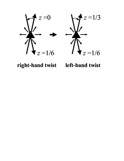
The next intermediate C-O layer is at , i.e. between the Mn layers at and , and for this layer all the components of tensor change sign due to inversion centers at . Thus the "chirality" of this layer is opposite to that of the first intermediate layer, hence the small twist angle between spins is also opposite and for the Mn layer at the spin orientation exactly coincides with the spin orientation for the Mn layer at (see Fig. 1). And then this repeats from layer to layer. We see that two alternating local twists, left and right, between neighboring Mn layers result in macroscopic canting angle between magnetic sublattices in centrosymmetric WF crystals.
If we change the sign of so that , then the layer "chirality" changes to opposite, change the sign and the twist angle also change the sign. From pure crystallographic point of view both values, and , are equivalent, they simply correspond to the lattice origin shifted at a half-period, from (0,0,0) to . In the crystallographic databases, both values of are cited for -Fe2O3; nevertheless sometimes the first-principle results for WF in -Fe2O3 do not indicate which value of they really adopt (see for instance Sandratski96 ). We see also that in crystals the sign of the Dzyaloshinskii–Moriya interaction changes to opposite at one half-period, therefore the idea to measure this sign by the Mössbauer absorption ozhogin68 cannot be correct.
According to symmetry there are six possible orientations of the WF moments (along plus and minus directions of three twofold axes; in Fig. 1, they are shown by short arrows, like in TablesA ). Application of an external magnetic field along one of these directions makes the corresponding ferromagnetic domain energetically favorable. And if the orientation of the ferromagnetic domain is fixed then the Dzyaloshinskii–Moriya interaction fixes the phase of antiferromagnetic sequence of moments in this domain Nathans64 .
Now we are ready to consider the main item of this paper: how to measure the sign of the Dzyaloshinskii–Moriya interaction in WFs? First of all, a strong enough magnetic field should be applied to obtain the single domain state where the Dzyaloshinskii–Moriya interaction pins antiferromagnetic ordering to the crystal lattice. Next, single-crystal diffraction methods sensitive both to oxygen coordinates and to the phase of antiferromagnetic ordering should be used. In other words, one should observe those Bragg reflections where interference between magnetic scattering on Mn atoms and nonmagnetic scattering on oxygen atoms is significant. There are three suitable techniques: neutron diffraction, Mössbauer -ray diffraction, and resonant x-ray scattering. We will discuss now their advantages and disadvantages.
Because of the layered magnetic structure alternating along -axis, the reflections with strong magnetic scattering correspond to the reciprocal lattice vectors with odd . At first let us consider scattering on oxygen atoms; the expressions for the oxygen structure amplitudes are similar for all three techniques and looks like ():
| (4) |
where is proportional to the oxygen atomic scattering factor (for x-rays) or to the nuclear scattering length (for neutrons); it is practically real because oxygen absorption is very small for thermal neutrons or hard x-rays. There is no contribution from carbon TablesA . Here and below some factors (such as atomic and magnetic formfactors, the Debye–Waller factor, etc.) are omitted because corresponding expressions are well known and implemented into routine computer programs used for diffraction experiments. It is clear from this equation that one should measure reflections with .
In the case of neutron diffraction, one can adopt the standard technique using the polarization ratio , i.e. the ratio of reflection intensities for incoming neutrons with spin parallel and antiparallel to the direction of applied magnetic field. For this ratio is given by the following expression containing interference between nuclear scattering by oxygen atoms and magnetic scattering by Mn atoms
| (5) | |||
| (6) |
where is the magnetic structure amplitude for reflection , , is the correspondent Fourier harmonic of the vector field describing the electron-magnetization distribution, is the sign of the Dzyaloshinskii–Moriya interaction between the first two layers of Mn atoms and includes all routine factors describing neutron magnetic scattering. Calculating (6) from (5) we took into account the geometry shown in Fig. 1 (i.e. is directed horizontally, is directed vertically so that if small canting is neglected, etc.). In particular, factor appears just because the phase of antiferromagnetic sequence is fixed by the Dzyaloshinskii–Moriya interaction. All other factors in Eq. (6) are more or less known and one can determine from rather rough measurements giving or . Notice that there is an additional condition for this measurements, , which appears in Eq. (6) from . To avoid confusion we should notice that expression (4) obeys threefold symmetry whereas magnetic scattering does not, because of the external field applied perpendicular to the threefold axis.
The technique of polarized neutron diffraction was used for measurements of the sign of small angular deviations of moments in MnF2 Brown81 but in that case the deviation is introduced by the single-spin anisotropy Moriya60 . To the best of our knowledge, there were no attempts to measure with this technique the sign of the Dzyaloshinskii–Moriya interaction.
In hematite (-Fe2O3), the situation is slightly more complicated because iron atoms are in the positions () with the point symmetry 3 and neighboring Fe layers are coupled either ferromagnetically or antiferromagnetically. Like in MnCO3, the symmetry is induced by oxygen atoms. The Fe layers coupled feromagnetically are related by inversion and, according to the Morya rules, there is no canting between them ( for inversion centers). The antiferomagnetic neighboring layers interact via an oxygen layer with symmetry 32 and alternating right and left twists of their moments lead to a macroscopic WF moment. Eq. (6) transforms to
| (7) |
The additional factor (where ) allows us to change the value and sign of magnetic scattering just changing . A suitable reflection (210 rhombohedral, i.e. hexagonal) had been studied in Nathans64 ; however, as it was noted in that paper, the result was controversial: in the great majority of observations, whereas would be expected from the symmetry of hematite. Thus we cant extract the sought sign of the Dzyaloshinskii–Moriya interaction and more careful experiments are needed.
It should be again emphasized that our symmetry-based arguments are only qualitative: the ab initio calculations for -Fe2O3 show that the torque induced by neighboring antiferomagnetic layer is opposite to the total torque Mazurenko05 . This confirms importance of suggested direct measurements of the sign of the total torque.
The Mössbauer diffraction can be used in a similar way. In this case, there is no need to vary the photon polarization and one can study intensity of reflections as a function of photon energy :
| (8) |
where is the magnetic Mössbauer structure factor of the reflections with . The function is well known Belyakov75 and its real part, which interferes with the first term in (8), changes sign when passes through resonances provided by the hyperfine splitting of nuclear levels. This should facilitate the observation of interference between the two terms. For 57Fe both terms in (8) may be of the same order of magnitude. The Mössbauer diffraction was observed in many crystals including WF -Fe2O3 Smirnov69 and FeBO3 Kovalenko77 (an analog of MnCO3) but these studies were concentrated mainly on pure magnetic scattering rather then on its interference with scattering on oxygen atoms. Contrary to neutrons, the Mössbauer diffraction can be used for very thin layers but the number of possible crystals is rather limited by the list of suitable Mössbauer isotopes.
Another promising approaches to the sign measurements can be related with resonant x-ray diffraction, i.e. diffraction near x-ray absorption edges. It is sensitive both to structural and magnetic ordering especially near absorption edges (see recent surveys Lovesey05 ; Dmitrienko05 ; Laan08 ). However, in magnetic metals, the edge is the only appropriate for diffraction, and for this edge magnetic scattering is several orders of magnitude smaller than conventional charge scattering by electrons. Thus, for reflections of type, the intensity is given by eq. (8) with the second term much smaller then the first one. Therefore the reliable observation of interference between two terms will be perhaps very difficult.
However, resonant x-ray scattering provides another nontrivial way to measure . The asymmetric oxygen environment of transition metals induces some additional anisotropy of their non-magnetic scattering amplitude, so that just owing to this anisotropy the reflections with can be excited even if . These reflections do not exist out of the resonant region and they are referred to as "forbidden reflections". There is no direct contribution to forbidden reflections from oxygen atoms, equation (4) gives zero, but the sign of the induced anisotropy depends on asymmetrical arrangement of the oxygen atoms and, correspondingly, the sign of the non-magnetic structure amplitude of forbidden reflections with is proportional to the sign of . For crystals with symmetry these reflections were first observed in -Fe2O3 Finkelstein92 . Then it was predicted that there should be some "chiral" dipole-quadrupole contribution to these reflections Dmitrienko01 and interference between different contributions (including magnetic scattering) have been studied in detail for -Fe2O3 and Cr2O3 crystals Kokubun08 . It was shown that the azimuthal dependence of reflection intensity could be strongly influenced by this interference (especially for the weak 009 reflection, see Figs. 11 and 12 from Kokubun08 ) and orientation of antiferromagnetic moment was determined in -Fe2O3 from the observed azimuthal dependence (without external magnetic field). Exactly the same measurements in orienting magnetic field would allow us to determine the sign of the Dzyaloshinskii–Moriya interaction.
The only problem with the last method is that we should rely on the sign of the x-ray anisotropy of iron atoms calculated with rather sophisticated computer codes. However it was proved experimentally for Ge Mukhamedzhanov07 that those codes (we used FDMNES Joly01 ) are rather reliable. It is worth noting that resonant x-ray diffraction and Mössbauer diffraction are element sensitive and moreover the former can distinguish orbital and spin contributions to magnetic moments.
In conclusion, we see that the experiments similar to those needed for the sign measurements had been already performed (some of them long time ago) for all three considered techniques. Therefore we believe that this paper will stimulate these measurements in different types of the weak ferromagnetics.
This work is partly supported by Presidium of Russian Academy of Sciences (program 27/21) and by the Russian Foundation for Basic Research (project 10-02-00768). Discussions with V.I. Anisimov and E.I. Kats are gratefully acknowledged.
Список литературы
- (1) . . , 32, 1547 (1957); Sov. Phys. JETP, 5, 1259 (1957).
- (2) I. Dzyaloshinsky, J. Phys. Chem. Solids 4, 241 (1958).
- (3) T. Moriya, Phys. Rev. Lett. 4, 228 (1960).
- (4) T. Moriya, Phys. Rev. 120, 91 (1960).
- (5) V. V. Mazurenko and V. I. Anisimov, Phys. Rev. B 71, 184434 (2005).
- (6) O. Nakanishi, A. Yanase, A. Hasegawa, and M. Kataoka, Solid State Commun. 35, 995 (1980).
- (7) P. Bak and M. H. Jensen, J. Phys. C: Solid State Phys. 13, L881 (1980).
- (8) Yu. I. Sirotin and M. P. Shaskolskaya, Osnovy Kristallofiziki (Nauka, Moskva (in Russian), 1975); Sirotine Yu. & Chaskolskaia, M. P. Fundamentals of Crystal Physics (Mir, Moscow (in English), 1982); Y. Sirotine and M. Chaskolskaia, Fondements de la Physique des Cristaux (Mir, Moscou (in French), 1984).
- (9) D. Coffey, K. S. Bedell, and S. A. Trugman, Phys. Rev. B 42, 6509 (1990).
- (10) D. Coffey, T. M. Rice, and F. C. Zhang, Phys. Rev. B 44, 10112 (1991).
- (11) . . , 46, 1420 (1964); Sov. Phys.- JETP, 19, 960 (1964).
- (12) S. V. Grigoriev, et al., Phys. Rev. Lett. 102, 037204 (2009).
- (13) . . , . . , . , , 1982.
- (14) International Tables for Crystallography. V. A. Space-Group Symmetry. Ed. T. Hahn. Dordreht: Springer, 2005.
- (15) L. M. Sandratskii and J. Kübler, Europhys. Lett. 33, 447 (1996).
- (16) V. I. Ozhogin, S. S. Yakimov, R. A. Voskanyan, and V. Ya. Gamlitskii, ZhETF Pis. Red. 8, 256 (1968); JETP Lett. 8, 157 (1968).
- (17) R. Nathans, S. J. Pickart, H. A. Alperin, and P. J. Brown, Phys. Rev. 136, 1641 (1964).
- (18) P. J. Brown and J. B. Forsyth, J. Phys. C: Solid State Phys. 14, 5171 (1981).
- (19) T. Moriya, Phys. Rev. 117, 635 (1960).
- (20) . . , 115, 553 (1975); V. A. Belyakov, Sov. Phys. Uspekhi 18, 267 (1975).
- (21) G.V. Smirnov, V.V. Sklyarevskii, R.A. Voskanyan, A.N. Artem’ev, ZhETF Pis. Red. 9, 123 (1969); JETP Lett. 9, 70 (1969).
- (22) P.P. Kovalenko, V.G. Labushkin, V.V. Rudenko, V.A. Sarkisyan, V.N. Seleznev, Pis’ma Zh. Eksp. Teor. Fiz. 26, 92 (1977); JETP Lett. 26, 85 (1977).
- (23) S. W. Lovesey, E. Balcar, K. S. Knight, and J. Fernández-Rodríguez, Phys. Rep. 411, 233 (2005).
- (24) V. E. Dmitrenko, K. Ishida, A. Kirfel, and E. N. Ovchinnikova, Acta Crystallogr. A 61, 481 (2005).
- (25) G. van der Laan, C. R. Physique, 9, 570 (2008).
- (26) K. D. Finkelstein, Q. Shen, and S. Shastri, Phys. Rev. Lett. 69, 1612 (1992).
- (27) V.E. Dmitrienko and E.N. Ovchinnikova, Acta Crystallogr. A 57, 642 (2001).
- (28) J. Kokubun, A. Watanabe, M. Uehara, Y. Ninomiya, H. Sawai, N. Momozawa, K. Ishida, and V.E. Dmitrienko. Phys. Rev. B 78, 115112 (2008).
- (29) E. Kh. Mukhamedzhanov, M. M. Borisov, A. N. Morkovin, A. A. Antonenko, A. P. Oreshko, E. N. Ovchinnikova, and V. E. Dmitrienko, Pis’ma Zh. Eksp. Teor. Fiz. 86, 896 (2007); JETP Lett. 86, 783 (2007).
- (30) Y. Joly, Phys. Rev. B 63, 125120 (2001); Program FDMNES http://www-cristallo.grenoble.cnrs.fr/simulation.