Cost-effective way to enhance the capabilities of the LCLS baseline
Abstract
This paper discusses the potential for enhancing the LCLS hard X-ray FEL capabilities. In the hard X-ray regime, a high longitudinal coherence will be the key to such performance upgrade. The method considered here to obtain high longitudinal coherence is based on a novel single-bunch self-seeding scheme exploiting a single crystal monochromator, which is extremely compact and can be straightforwardly installed in the LCLS baseline undulator. We present simulation results dealing with the LCLS hard X-ray FEL, and show that this method can produce fully-coherent X-ray pulses at 100 GW power level. With the radiation beam monochromatized down to the Fourier transform limit, a variety of very different techniques leading to further improvements of the LCLS performance become feasible. In particular, we describe an efficient way for obtaining full polarization control at the LCLS hard X-ray FEL. We also propose to exploit crystals in the Bragg reflection geometry as movable deflectors for the LCLS X-ray transport systems. The hard X-ray beam can be deflected of an angle of order of a radian without perturbations. The monochromatization of the output radiation constitutes the key for reaching such result. Finally, we describe a new optical pump - hard X-ray probe technique which will allow time-resolved studies at the LCLS baseline on the femtosecond time scale. The principle of operation of the proposed scheme is essentially based on the use of the time jitter between pump and probe pulses. This eliminates the need for timing XFELs to high-power conventional lasers with femtosecond accuracy.
DEUTSCHES ELEKTRONEN-SYNCHROTRON
Ein Forschungszentrum der
Helmholtz-Gemeinschaft
DESY 10-133
August 2010
Cost-effective way to enhance the capabilities of the LCLS baseline
Gianluca Geloni,
European XFEL GmbH, Hamburg
Vitali Kocharyan and Evgeni Saldin
Deutsches Elektronen-Synchrotron DESY, Hamburg ISSN 0418-9833 NOTKESTRASSE 85 - 22607 HAMBURG
1 Introduction
The LCLS, the world’s first hard X-ray FEL, has demonstrated SASE lasing and saturation at 0.15 nm LCLS2 . The SASE X-ray beams are characterized by full transverse coherence, but due to the inherent nature of the SASE process, the pulses only possess partial longitudinal coherence. This is a consequence of the fact that in SASE FEL the amplification process start up from noise. The coherence time is defined by inverse spectral width.
For conventional XFELs LCLS2 -SPRIN , the typical pulse bandwidth is much larger than the Fourier transform limited value for the radiation pulse duration.
Self-seeding schemes have been studied to reduce the bandwidth of SASE X-ray FELs SELF -OURY3 . A self-seeded XFEL consists of two undulators with an X-ray monochromator located between them. The first self-seeding scheme was proposed in the VUV and soft X-ray region, and makes use of a grating monochromator SELF . The implementation of such scheme for hard X-ray range would exploit a crystal monochromator SXFE . Self-seeding schemes proposed in SXFE makes use of a four-crystal, fixed-exit monochromator in Bragg reflection geometry. The X-ray pulse thus acquires a cm-long path delay, which must be compensated. For a single-bunch self-seeding scheme this requires a long electron beam bypass, implying modifications of the baseline undulator configuration. To avoid this problem, a double bunch self-seeding scheme based on special photoinjector setup was proposed in OURL , HUAN , based on the double-bunch production scheme DOUB .
In OURX -OURY3 we proposed to use a new method of monochromatization exploiting a single crystal in Bragg transmission geometry. A great advantage of this method is that the single crystal monochromator introduces no path delay of X-rays. This fact eliminates the need for long electron beam bypass, or for the creation of two precisely separated identical electron bunches, as required in the other self-seeding schemes. In some experimental situations, the simplest two-undulator configuration for self-seeding scheme is not optimal. The obvious and technically possible extension is to use a setup with three or more undulators separated by monochromators. This cascade scheme, exemplified in OURY2 for the baseline undulators at the European XFEL, is distinguished, in performance, by a small heat-loading of crystals at a very high repetition rate.
The situation with heat loading of crystal changes when one considers the case of LCLS, which is characterized by much lower repetition rate. In this case, the simplest two-undulator configuration may be practically advantageous. This paper describes such almost trivial setup for the LCLS baseline. Using a single crystal installed within a short ( m-long) magnetic chicane in the LCLS baseline undulator, it is possible to decrease the bandwidth of the radiation well beyond the LCLS SASE FEL design, down to the Fourier limit given by the finite duration of the pulse. In the single-bunch self-seeding scheme proposed here for LCLS, no time dependent elements are used, and problems with synchronization and time jitter do not exist at all. The installation of the chicane does not perturb the undulator focusing system and allows for a safe return to the baseline mode of operation. The inclusion of a chicane is not expensive and may find many other applications OUR01 -OUR05 . We present simulation results for the LCLS baseline undulator, with electron beam parameters based on the LCLS commissioning results. In particular, we will use the LCLS low-charge mode of operation ( nC) to demonstrate the feasibility of proposed scheme. The wakefield effects from the linac and from the undulator vacuum chamber are much reduced at such low charge.
At that point, there still remains room for improving the output characteristics of the XFEL. The most promising way to increase the output power is by tapering the magnetic field of the undulator TAP1 -TAP4 . Significant further increase in power is achievable by starting the FEL process from a monochromatic seed rather than from noise FAWL , CORN , WANG . The baseline LCLS undulator is long enough (33 cells) to reach a 100 GW level monochromatic output by tapering the undulator parameter of about over the last 10 cells, following monochromatization (11 cells) and saturation (12 cells). It should be further noted that the proposed self-seeding scheme could be applied at higher charge modes of operation as well. In particular, the nC mode of operation of the LCLS, relying on the self-seeded hard X-ray technique, ultimately leads to an increase in peak brilliance of two orders of magnitude.
Once highly monochromatic X-ray beam can be obtained from the baseline undulator, a variety of very different techniques for further performance improvement of the LCLS become feasible. In particular, the high monochromatization of the output radiation constitutes the key for obtaining full polarization control at the LCLS hard X-ray FELs. So far, two different approaches have been used for the production of circularly-polarized photons with synchrotron radiation; (i) special insertion devices such as APPLE-type undulators SASA , and (ii) X-ray phase retarders HIRA , FREE . The first method is currently being discussed for XFEL projects tdr-2006 . The second method has not drawn much attention so far, because the retarding plate technique is effective only when the bandwidth of the x-ray beam is sufficiently small not to blur the polarization state. In order to adapt the phase retarder technique to X-ray SASE FEL beamlines it is necessary to add a crystal monochromator to reduce the bandwidth of the incoming beam and to get well-defined circularly-polarized photons. A monochromator can be located in the experimental hall, but the beam intensity available to the phase retarder becomes, in this case, very weak. Orders of magnitude higher throughput can be achieved when the monochromator is located in the baseline undulator, because the installation of a crystal monochromator in the undulator (for the realization of the self-seeding scheme) always leads to an improvement in terms of spectral flux density.
Our self-seeding setup is very flexible and can be naturally taken advantage of in different schemes. In particular, it can be used as an ultrafast X-ray pulse measurement setup. The measurement of X-ray pulses on the femtosecond time scale constitutes today an unresolved problem. It is possible to create a few femtosecond X-ray pulses from LCLS in the low-charge mode of operation, but not to measure them. In OUR05 we proposed a new method for the measurement of the duration of femtosecond X-ray pulses. In this paper we demonstarte that the self-seeding setup may be used at LCLS for this purpose too. We also show the advantage of our self-seeding setup when dealing with pump-probe techniques. One of the main technical problem for building femtosecond time-resolved capabilities is the synchronization between optical pump and hard-X-ray probe pulses with femtosecond accuracy. In this paper we propose a new scheme for optical pumphard X-ray probe femtosecond resolution experiments at the LCLS baseline. The principle of operation of this scheme is essentially based on the exploitation of the time jitter between optical and hard X-ray pulses. We shift the attention from the problem of synchronization between pump and probe pulses to the problem of synchronization between two hard X-ray probe pulses with tunable delay and decoupled wavelength. It is proposed to derive both probe hard X-ray pulses from the same electron bunch but from different parts of the LCLS baseline undulator, which has a few percent adjustable gap. This eliminates the need for synchronization and any jitter problem. The delay between the two probe hard X-ray pulses can be introduced in the baseline undulator without the need for dispersive X-ray optical elements (crystals). The idea is to exploit the self-seeding setup, and in particular, for this purpose, the magnetic chicane.
Finally, we note that the LCLS Far Experimental Hall is an underground structure which containts only three experimental stations. A natural step for expanding the LCLS capabilities would be the addition of a further experimental hall to be built on the surface. Hard X-ray beams could be distributed to this experimental hall by the LCLS baseline undulator. The main problem in accomplishing this task is that it would require to deflect the full radiation pulse of an angle of order of a radian without perturbation. A high monochromatization of the output radiation constitutes the key for reaching such result. Crystal deflectors located in the LCLS X-ray transport systems would in fact allow the hard X-ray FEL beam to be redirected from the far Experimental Hall to any other hall.
2 Possible self-seeding scheme with a wake monochromator for the LCLS baseline undulator
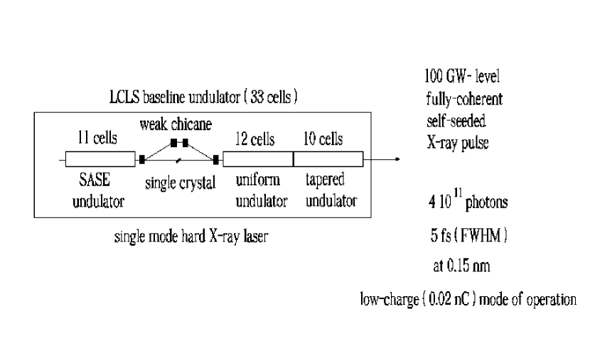
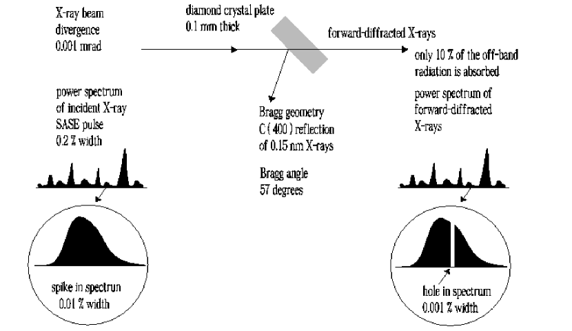
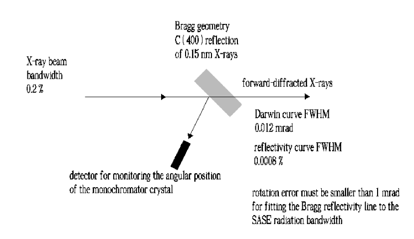
In its simplest configuration, a self-seeded FEL consists of an input and an output undulator separated by a monochromator. With reference to Fig. 1 we study the simplest two-undulator configuration case for a self-seeding setup. The first undulator in Fig. 1 operates in the linear high-gain regime starting from the shot-noise in the electron beam. After the first undulator, the output SASE radiation passes through the monochromator, which reduces the bandwidth to the desired value. A distinguishing feature of our method is that it uses a single crystal in the Bragg transmission geometry, instead of a fixed exit four-crystal monochromator. As a result, the X-ray optics is extremely simple to align: in involves no beam recombining and no scanning of the delay. According to the wake monochromator principle, the SASE pulse coming from the first undulator impinges on the crystal set for Bragg diffraction. Then, the single crystal in Bragg geometry operates as a bandstop filter for the transmitted X-ray SASE radiation pulse, as shown in Fig. 2. When the incident angle and the spectral contents of the incoming beam satisfy the Bragg diffraction conditions, the temporal waveform of the transmitted radiation pulse shows a long monochromatic wake. The duration of this wake is inversely proportional to the bandwidth of the absorption line in the transmittance spectrum. The alignment tolerance of the crystal angle is expected to be in the range of the mrad, in order to fit the Bragg reflectivity line to the SASE radiation bandwidth, Fig. 3.
While the radiation is sent through the crystal, the electron beam passes through a magnetic chicane, which accomplishes three tasks: it creates an offset for the crystal installation, it removes the electron microbunching produced in the first undulator, and it acts as a delay line for the implementation of a temporal windowing process. In this process, the magnetic chicane shifts the electron bunch on top of the monochromatic wake created by the bandstop filter thus temporally selecting a part of the wake. By this, the electron bunch is seeded with a radiation pulse characterized by a bandwidth much narrower than the natural FEL bandwidth. For the hard X-ray wavelength range, a small dispersive strength in the order of a few microns is sufficient to remove the microbunching generated in the first undulator part. As a result, the choice of the strength of the magnetic chicane only depends on the delay that one wants to introduce between electron bunch and radiation. The optimal value amounts to m for the low-charge mode of operation. Such dispersion strength is small enough to be generated by a short ( m-long) magnetic chicane to be installed in place of a single undulator module. Such chicane is, at the same time, strong enough to create a sufficiently large transverse offset for installing the crystal.
The setup proposed will produce fully coherent X-ray pulses. In order to increase the output power, tapering tachniques are foreseen TAP1 -TAP4 . Tapering consists in a slow reduction of the field strength of the undulator in order to preserve the resonance wavelength as the kinetic energy of the electrons decreases due to the FEL process. The undulator taper could be simply implemented in steps from one undulator module to the next, and is provided by changing the undulator gap. Since here we start the FEL process from a monochromatic seed, rather than from noise, tapering becomes particularly efficient FAWL , CORN , WANG .
Fig. 1 shows the design principle of our setup for high power mode of operation. After the cell-long SASE input undulator and the monochromator, an output undulator follows, consisting of two sections. The first section is composed by uniform cells, while tapering is implemented in the second section, consisting of cells. The monochromatic seed is exponentially amplified by passing through the first uniform section of the output undulator. This section is long enough to reach saturation, and yields an output power of about GW. Such monochromatic FEL output is finally enhanced up to the GW-level in the second output-undulator section, by tapering the undulator parameter of about over the last cells after saturation. In summary, our scheme aims to generating GW-level, fully-coherent X-ray pulses in the tapered LCLS baseline undulator by means of a self-seeding technique, which produces a highly monochromatic seed.
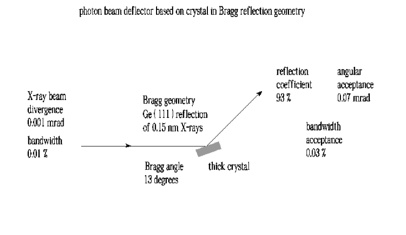
With the radiation beam monochromatized down to the Fourier transform limit, a variety of different techniques leading to enhance the LCLS capabilities become feasible. In particular, it is possible to use crystals in Bragg reflection geometry as movable deflectors, Fig. 4. For example, for the Ge(111) reflection, the angular acceptance of the crystal deflector is of the order of rad and the spectral bandwidth is about . Thus, the angular and frequency acceptance of the deflector are much wider compared to the photon beam divergence and bandwidth, which are respectively of the order of a microradian, and for the low-charge mode of operation. It is therefore possible to deflect the full photon beam without perturbations. About of the reflectivity can be achieved for wavelengths around nm. Once experience with self-seeding setup operations will be available, it will be possible to implement such crystal deflectors for the benefit of the LCLS X-ray transport system.
3 Self-seeding - key to obtain full polarization control at LCLS hard X-ray FEL
A particularly useful feature becoming easily available with the production of highly monochromatized radiation using self-seeding technique is the full control over the polarization state of the FEL radiation pulse. As mentioned in the Introduction, the idea that we develop in this paper is based on the straightforward use of X-ray phase retarders HIRA , FREE , rather than on the installation of special insertion devices. X-ray retarders are birefringent crystals having different indexes of refraction along two orthogonal axis. When the thickness of these crystals is such that the induced phase shift between two orthogonal electric fields pointing along these axis is just , they behave as quarter wave plates. As is well-known, if a quarter wave plates is adjusted in a way that the axis directions make an angle of rad with respect to the linear polarization direction of the incident beam, then the particular phase retardation transforms the linearly polarized field into a circularly polarized field, right-handed or left-handed depending on the sign of the phase shift. Birefringence for X-rays occurs in perfect crystals near the Bragg diffraction. The most convenient way to take advantage of such effect is to use the forward-diffracted (i.e. transmitted) beam outside the reflection range.
The ideal performance of X-ray phase retarders is achieved when the incoming beam has no angular divergence nor photon energy spread. Such an incoming beam has a definite deviation from the exact Bragg condition, hence suffers a definite phase retardation between - and -polarization components. The incoming beam from an X-ray SASE FEL is linear polarized and has a sufficiently small angular divergence, but a large photon energy spread, which would blur the polarization state. Thus, in order to adapt the phase retarder to the X-ray SASE FEL beamlines it is necessary to add a crystal monochromator to reduce the bandwidth of the incoming beam and to get a well-defined circular-polarization state. If the monochromator is located in the experimental hall, the beam intensity on the retarder becomes rather weak. It is therefore desirable to install the monochromator already within the baseline undulator. Of course, this situation is automatically realized when our self-seeding scheme is implemented. The self-seeding thus proves to be the key for obtaining full polarization control of the FEL pulse. Quarter wave plates can probably be used to transform the linear polarization delivered by a planar XFEL undulator into circular polarization without any major difficulty. Compared to specially designed undulators delivering circular polarization, there are some advantages in using quarter wave plates: the switching of the polarization handedness is easily done by small rotations of the crystal and therefore very easy to handle, and the cost is much lower than for the corresponding undulator setup. However, quarter wave plates have the heavy disadvantage that they are well-suited for the hard X-ray wavelength range only.
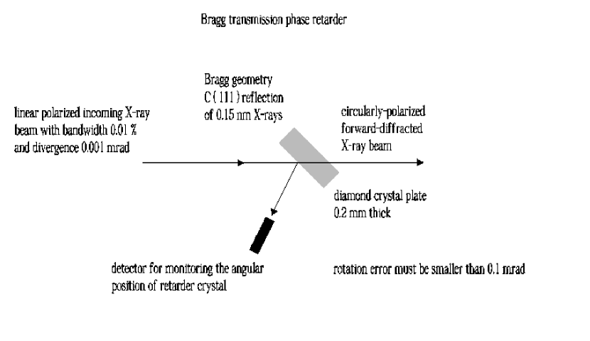
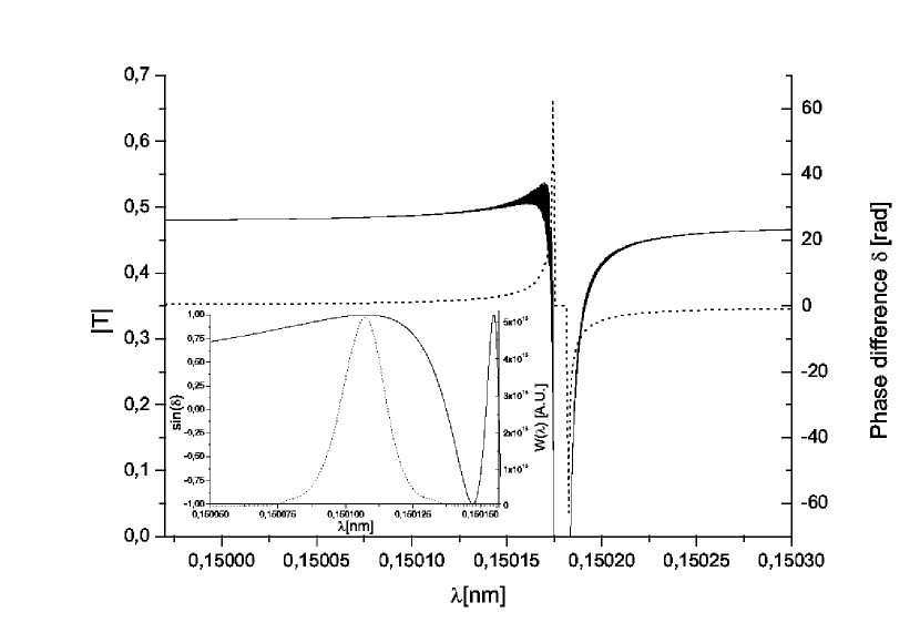
For a given reflection and wavelength, one has to optimize the beam path in the crystal with respect to the phase shift and to the transmission. It is generally necessary to use a crystal with as little absorption as possible. Practically, thick diamond crystals may be used as quarter wave plates. Thicker phase retarders of lighter materials become a quarter wave plate far on the tails of the Bragg peak, and phase retardation becomes more insensitive to the bandwidth of the incoming beam. For our calculations we used the symmetric 111 reflection of a diamond crystal in Bragg geometry, mm-thick at 8 keV, combined with the self-seeded LCLS X-ray FEL operated in the low-charge mode, Fig. 5. Results are shown in Fig. 6. The main plot shows the modulus of the transmittance relevant to the Bragg (111) diffraction of X-rays at nm from such diamond crystal (-polarization), and the phase difference between - and -polarization components, which is indicated with . In Section 5 we discuss the approximation that we used for calculating the phase-difference , which is plotted in the inset (solid line), and its accuracy. In order obtain the maximum degree of circular polarization we need to tilt the crystal in such a way that the maximum of the impinging radiation spectrum coincides with the value on the tail of the phase difference . The average degree of circular polarization from the transmitted beam is then found as
| (3) |
where is the averaged spectrum and integrals are performed over all frequencies. The resultant maximum for the case under examination has been estimated to be .
In closing this Section, it should be noted that the proposed setup for polarization control is characterized by energy-tunability and helicity-switchability. Wide energy tunability is attainable because the phase retardation is controlled through the deviation angle from the exact Bragg condition. Helicity switching is quite easy to obtain because, as mentioned above, the sign of the phase shift is reversed for the opposite angular sides of the exact Bragg condition.
4 Phase shift of forward-diffracted X-rays
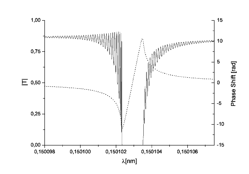
In OURX , OURY2 we discussed about the relation between modulus and phase of the transmittance of the diamond crystal used in the monochromatization procedure in terms of Kramers-Kronig relations. The modulus of the transmittance, calculated on the basis of the dynamical theory of diffraction WECK , and the phase, recovered with the help of the Kramers-Kronig approach implemented in the software package LUC2 , are shown in Fig. 7 for the case of Bragg (400) diffraction of X-rays at nm from a diamond crystal with a thickness of mm. In this Section we present a thorough justification for the relation between modulus and phase.
X-ray multiple scattering in a perfect crystal is described by the dynamical theory of X-ray diffraction (see e.g. AUTH for a comprehensive treatment). Consider an X-ray beam incident on a crystal in symmetric Bragg geometry. According to the dynamical theory of diffraction, when the incident angle of radiation is in the vicinity of Bragg’s diffraction condition, one can write the modulus of the transmittance in Bragg geometry as in AUTH :
| (4) | |||
| (5) | |||
| (6) |
where is the crystal thickness, is the extinction length, and is known in literature as the deviation parameter, which best describes the theory results. When absorption is neglected, is real. Adding a subscript to stress reality, can be written as
| (7) |
where is the Darwin width of the reflectivity curve, is the angular departure from the Bragg’s angle, and is the departure of the middle of the reflection domain from the Bragg’s angle. Therefore gives, altogether, the angular departure from the middle of the reflection domain. Usually one is interested in the transmission, or in the reflection curve at a fixed frequency of incident radiation, as a function of the deviation from the Bragg’s angle. In this paper, instead, we consider the incident angle of the radiation fixed near the Bragg’s angle111In our case of interest we have an angular divergence of the incident photon beam of about a microradian, which is much smaller than the Darwin width of the rocking curve (rad.) As a result, we assume that all frequencies impinge on the crystal at the same angle in the vicinity of the Bragg diffraction condition. Note that mirror reflection takes place for all frequencies and, therefore, the reflected beam has exactly the same divergence as the incoming beam., and we scan through the frequency deviation from the frequency associated to the Bragg’s angle by Bragg’s law222Note that the incidence angle can be tuned once and for all in order to center the rocking curve at the desired frequency by slightly tilting the crystal. This means that we are free to select a given within the spectrum of the incoming radiation corresponding to a particular Bragg’s angle .. A given fixed incidence angle corresponds to the Bragg’s angle for a certain frequency through the Bragg’s law. As concerns the value of the deviation parameter, once the incidence angle is fixed deviations in frequency correspond to deviations from the Bragg’s angle. In particular, for , Bragg’s law allows one to write the relation between and as
| (8) |
yielding
| (9) |
This means that, aside for a shift given by the term in , . The previous discussion holds in absence of absorption. When absorption is included, , and become complex. In particular where , and expressions for and (together with those for and and a detailed derivation of results) can be found in AUTH .
Having discussed the relation between and , one can use Eq. (6) to plot the modulus of the transmissivity as a function of the frequency. At this stage, the phase of the transmissivity remains, however, unknown. A straightforward way of calculating it, is by applying again, explicitly, the dynamical theory of diffraction AUTH . In previous works of us OURX , OURY2 , we chose an alternative derivation, based on the use of Kramers-Kronig relations, which we briefly review here. Let us regard our crystal as a filter with transmission . According to Titchmarsch theorem (see LUCC and references therein for a recent review on the subject) causality333Causality simply requires that the filter can respond to a physical input after the time of that input and never before. and square-integrability of the inverse Fourier transform of , which will be indicated with , is equivalent444Here we are tacitly assuming, as required by Titchmarsh theorem, that is a square integrable function. This is physically reasonable, since there will always be some cutoff frequency for which the filter does not transmit anymore. Strictly speaking, the mathematical model of in Eq. (6) is not square integrable. One should therefore understand a certain cutoff frequency in the definition in Eq. (6). The presence of such cutoff does not change the following considerations. to the existence of an analytic continuation of to on the upper complex -plane (i.e. for ). The same theorem also shows that the two previous statements are equivalent to the fact that real and imaginary part of are connected by Hilbert transformation. Since must be real (thus implying that ), from the Hilbert transformation follows the well-known Kramers-Kroninig relations KRAM , KRON :
| (10) | |||
| (11) |
linking real and imaginary part of . A similar reasoning can be done for the modulus and the phase , see TOLL . In fact, one can write
| (12) |
Note that implies that and that . Therefore, using Eq. (12) one also has that . Then, similarly as before, application of Titchmarsh theorem shows that the analyticity of on the upper complex -plane implies that
| (13) |
A direct use of Eq. (13), with given as in Eq. (6), should yield back the phase . As is well known however, in applying such procedure one tacitly assumes that is analytical on the upper complex -plane. While causality implies this fact for , it does not imply it automatically for . In fact, such function is singular where . If has zeros on the upper complex plane, these zeros would contribute adding extra terms to the total phase. For this reason, Eq. (13) is known as minimal phase solution.
In the following we show that in our case does not have zeros on the upper complex plane, and that the minimal phase solution is actually the complete solution to the phase problem. To this end, it is sufficient to study the zeros of , where is given in Eq. (6) as a function of the complex parameter. In fact, from Eq. (8) and from follows that
| (14) |
Consider now the analytic continuation of to the upper complex -plane. In passing, note that must be analytic on such half plane, because the filter is causal, meaning that for . We have to show that has no zeros on the complex half plane. In order to demonstrate this, it is sufficient to demonstrate that has no zero in the entire complex -plane. First note that the numerator of Eq. (6) becomes zero for only. However, in these points, the denominator becomes zero too. Using, e.g. de l’Hopital rule one can show that the limit for is finite. Finally, the denominator never goes to infinity (except for ). We can therefore conclude that the analytic continuation of has no zeros in the upper -plane. Therefore Titchmarsch theorem applies, and the minimal phase solution considered in previous papers OURX , OURY2 is the correct one.
5 Theoretical background of phase retarders in Bragg transmission geometry
In this Section we justify the treatment of phase retarders proposed in Section 3, with reference to HIRA and FREE . In fact, results in Section 3 are based on the thick-crystal approximated formula given in HIRA to calculate the phase difference between - and -polarization components. Here we will introduce the thick-crystal approximation for such phase difference and show that, albeit not accounting to absorption, it constitutes a good approximation for our purposes. We have not found discussions about the accuracy of this approximated formula anywhere in published literature. We will limit ourselves to showing that in a few examples, the simplified approach gives the same results as the exact expression for the phase of the transmittance.
First it should be noted that the only relevant quantity needed in order to calculate the degree of circular polarization is the phase difference between the crystal transmittance in the and polarization directions. This fact can be easily seen considering the definition of the circular degree of polarization in terms of Stokes parameters and :
| (15) |
Here
| (16) | |||
| (17) | |||
| (18) |
where is any unitary complex vector, while and are the complex electric field components, in the frequency domain, along the and the directions. Introducing notations for intensities and for phases, so that , and working out elementary calculations, one finds that
| (19) |
where we further introduced notation for the phase difference. spans from (fully circularly polarized radiation, right handed helicity) to (fully circularly polarized radiation, left handed helicity). In order to obtain , one needs to have and , meaning . If the - and -polarization components are characterized by the same absorption, the former requirement can be fulfilled orienting the crystal in such a way that both the and direction form an angle of with respect to the direction of polarization of the impinging light, which is linearly polarized. Otherwise, such orientation will differ from . When , Eq. (19) reduces to .
The next step is to find out an expression for . In the limit for a large thickness of the crystal, the transmittance is given by AUTH :
| (20) |
where is the crystal thickness, and is the extinction length. In this case the phase of the transmittance is just
| (21) |
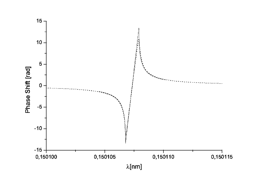
As an example, a comparison between Eq. (21) and the exact phase relevant to the Bragg 400 diffraction of X-rays at nm from a Diamond crystal with a thickness of mm, already plotted in Fig. 7, is given in Fig. 8 for the -polarization component. We hold the accuracy of Eq. (21) as sufficient for our purposes.
It is important to note that Eq. (20) and Eq. (21) apply to both and polarization components. However, one has AUTH that and , where subscripts and indicate the different polarization components. It follows that , which depends on as , also depends on the polarization component as . Therefore, the linear term in Eq. (21) is the same for both polarization components and cancels when one calculates the phase difference . It follows that
6 FEL simulations
Following the introduction of the proposed method and the previous theoretical Sections, in the present Section we report on a feasibility study of the single-bunch self-seeding scheme with a wake monochromator for the LCLS. This feasibility study is performed with the help of the FEL code GENESIS 1.3 GENE , running on a parallel machine, for the low-charge mode of operation ( nC) corresponding to a bunch length of about fs. Parameters are presented in Table 1.
| Units | ||
| Undulator period | mm | 30 |
| K parameter (rms) | - | 2.466 |
| Wavelength | nm | 0.15 |
| Energy | GeV | 13.6 |
| Charge | nC | 0.02 |
| Bunch length (rms) | m | 1 |
| Normalized emittance | mm mrad | 0.4 |
| Energy spread | MeV | 1.5 |
6.1 SASE undulator and wake monochromator
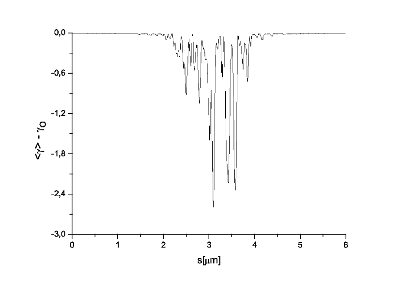
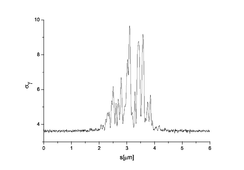
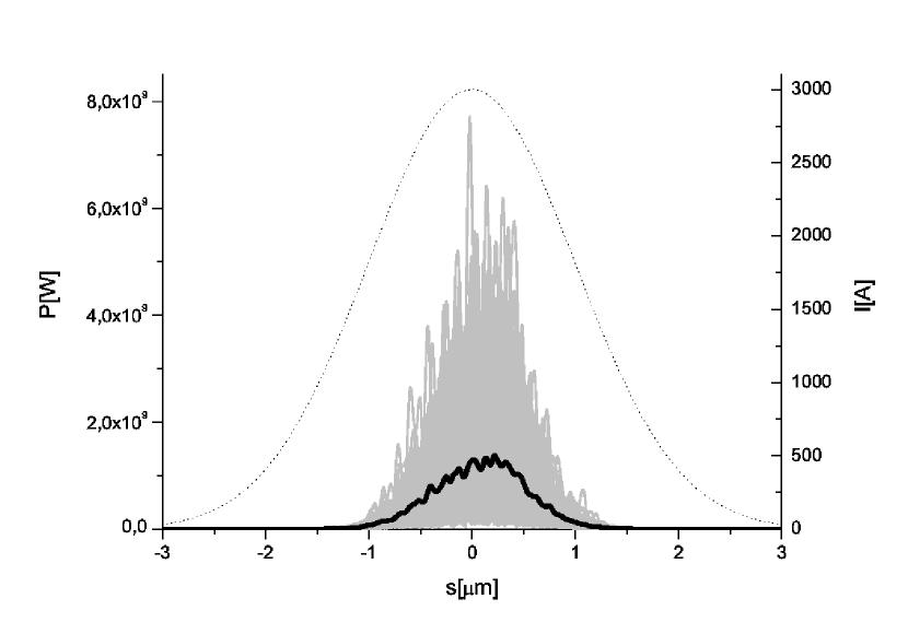
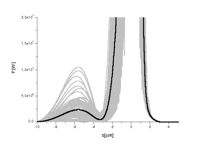
With reference to Fig. 1, the electron beam first passes the 11 cells of the SASE undulator. The FEL is still in the linear regime, so that energy losses and energy spread induced by the FEL process are small enough. As a result, the electron beam can still lase, see Fig. 9 and Fig. 10. The output power is shown in Fig. 11.
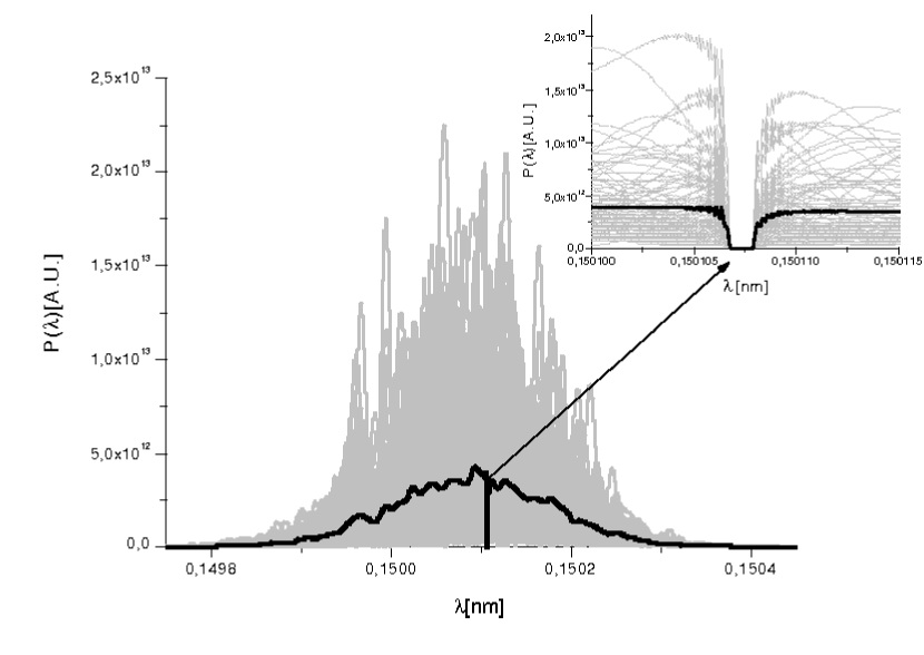
Following the SASE undulator, the photon pulse is filtered through the wake monochromator, while the electron beam is sent through the short chicane. As explained before, the crystal acts as a bandstop filter. Such effect is best seen in terms of the spectrum in Fig. 12, where we show a comparison between spectra before and after the filter. The effect is highlighted in the inset. The corresponding power is shown in Fig. 13. As discussed before, monochromatization does not take place in the frequency domain. At first glance, the passage through the bandstop filter is only responsible for slight changes in the power distribution along the pulse. However, a zoom of the vertical axis shows what we are interested in: a long, monochromatic tail in the power distribution on the left side of the picture, Fig. 13. Note that there is no corresponding tail on the right side of Fig. 13. As already noticed in OURX , this fact is consistent with causality.
6.2 First output undulator
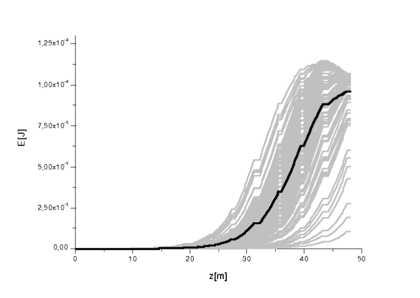
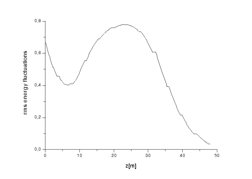
Photons and electrons are recombined after the crystal, so that the electron bunch temporally selects a part of the long wake in Fig. 13, and is seeded by it. The seeded electron beam goes through the first output undulator, Fig. 1, which is sufficiently long (12 cells) to reach saturation. Fig. 14 shows the output energy as a function of the position inside the undulator, while in Fig. 15 we plot the rms energy fluctuations, as a function of the position inside the undulator as well. As noted e.g. in OURY2 , at the beginning of the undulator the fluctuations of energy per pulse apparently drop. This can be explained considering the fact that the Genesis output consists of the total power integrated over the full grid up to an artificial boundary, i.e. there is no spectral selection. Therefore, our calculations include a relatively large spontaneous emission background, which has a much larger spectral width with respect to the amplification bandwidth and which fluctuates negligibly from shot to shot. Since there is a long lethargy of the seeded radiation at the beginning of the FEL amplifier, one observes an apparent decrease of fluctuations. Then, when lethargy ends, the seed pulse gets amplified and fluctuations effectively return to about the same level as after monochromator.
6.3 Tapering section
Finally, the tapering section follows. The simulations from Section 6.2 where made by choosing the number of uniform undulator sections in order to optimize the output characteristics. Similarly, in the simulations including tapering, both an optimized number of uniform and tapered sections have been chosen. The total number of section from the first input undulator to the output is , and we used 9 uniform cells and 12 tapered cells.
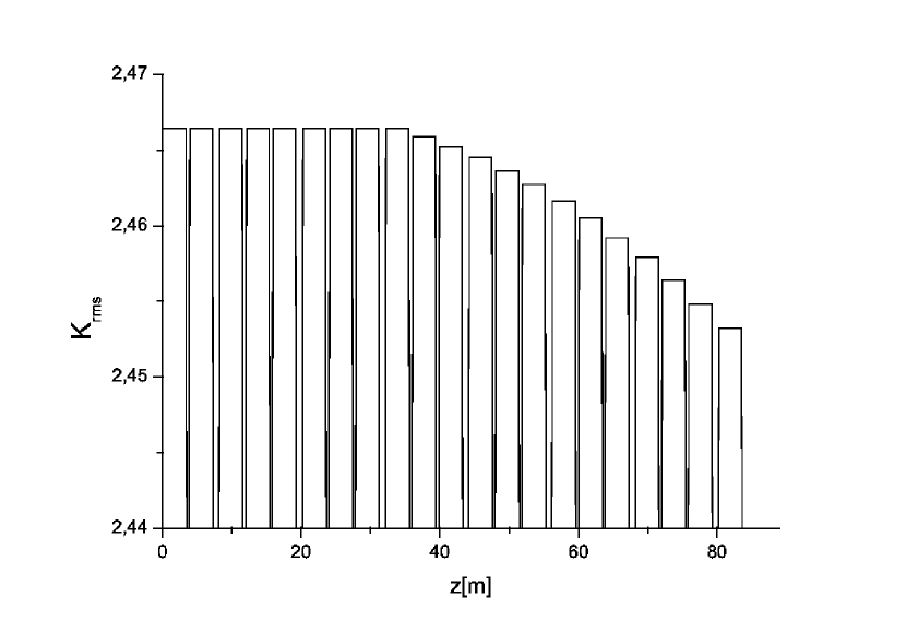
The value of the rms parameter in Table 1 refers to the untapered sections. The optimal555Note that additional tapering should be considered to keep undulators tuned in the presence of energy loss from spontaneous synchrotron radiation. In Fig. 18 we present a tapering configuration which is to be considered as an addition to this energy-loss compensation tapering. tapering configuration is presented, instead, in Fig. 18. Such law has been determined phenomenologically, with the help of numerical experiments. The effective value of K is kept constant through each undulator segment. In other words, tapering consists of a stepwise change of K from segment to segment (segment tapering).
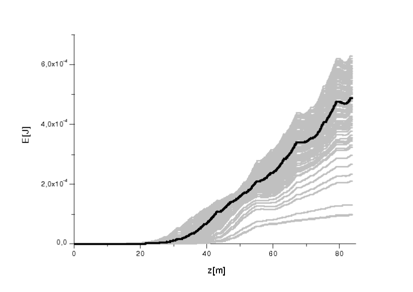
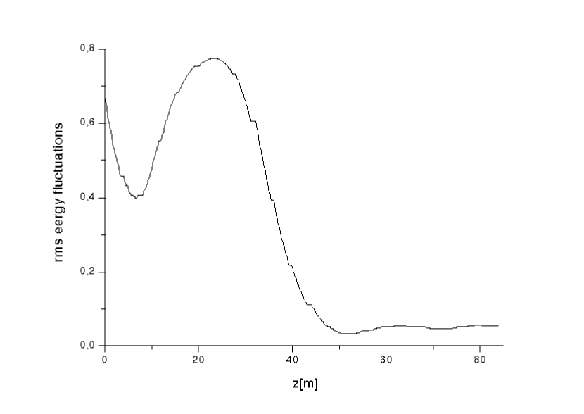
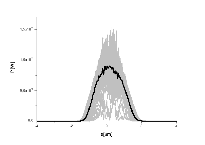
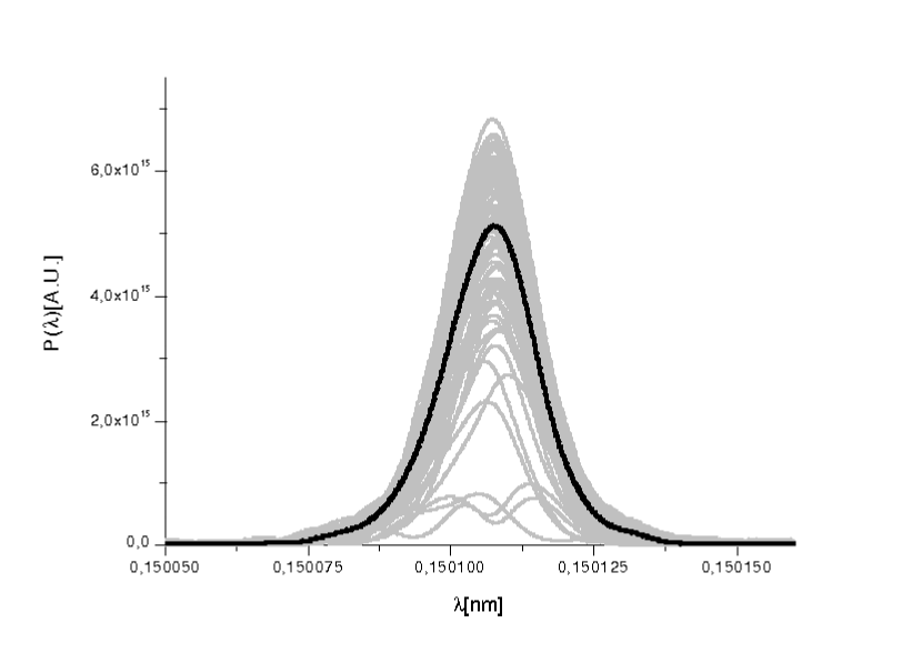
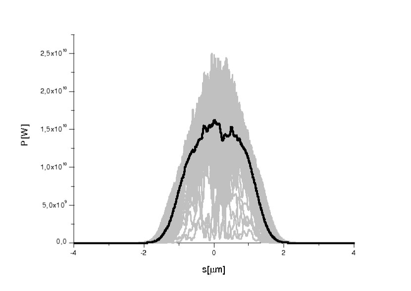
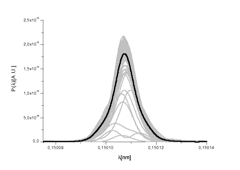
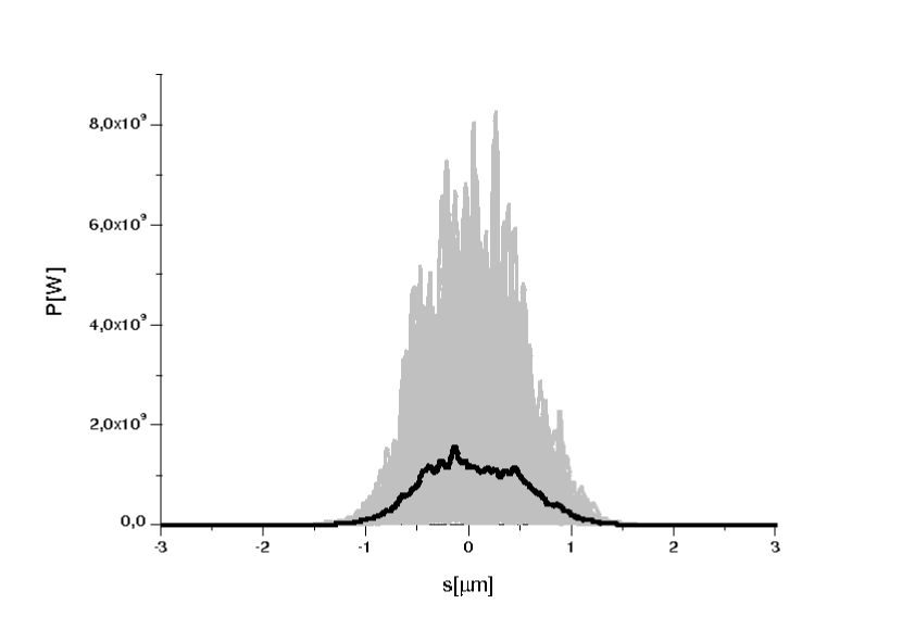
Fig. 19 shows the increase of energy in the radiation pulse as a function of the position inside the undulator. The rms energy deviation from the average as a function of the distance inside the output undulator is shown in Fig. 20. Fluctuations at the output of the device are less than . Fig.re 21 and Fig. 22 respectively show the output power and spectrum. In synthesis, the outstanding spectral properties (the bandwidth is still of order ) and the good stability in terms of shot-to-shot energy fluctuations is retained, while the power is increased to the GW-level.
7 Flexibility of the self-seeding setup installed in the LCLS baseline undulator
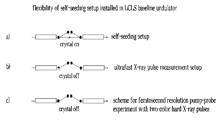
The two-undulator configuration in Fig. 1 can be naturally taken advantage of in different schemes, as shown in Fig. 23. The upper figure (a) shows the present self-seeding scheme.
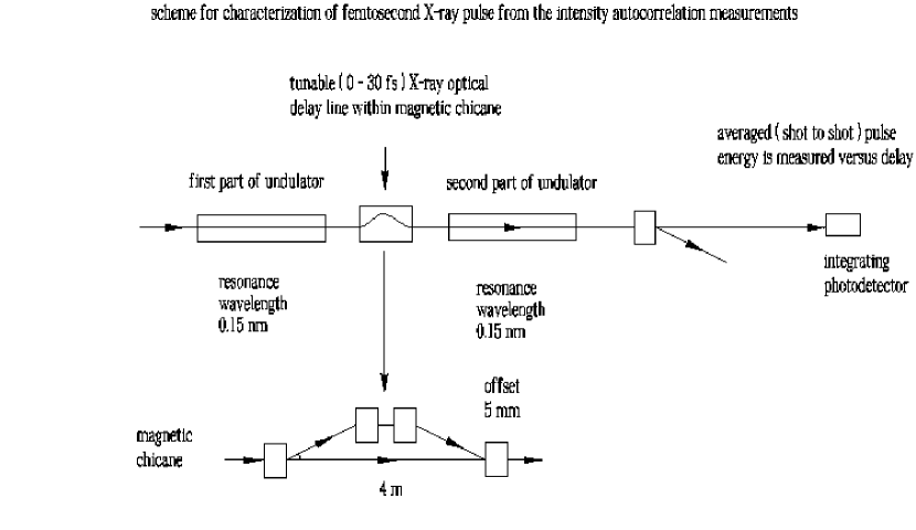
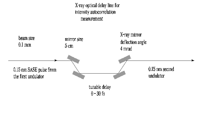
The middle figure (b) refers to the ultra short X-ray pulse measurement setup proposed in OUR05 , which makes use of the magnetic chicane. The measurement of X-ray pulses on the femtosecond time-scale constitutes an unresolved problem. In fact, it is possible to create sub-ten femtosecond X-ray pulses from LCLS in the low-charge mode of operation, but not to measure their duration. In OUR05 we proposed a novel method for measuring the duration of femtosecond X-ray pulses from XFELs. The method is based on the measurement of the autocorrelation function of the X-ray pulses. The setup in Fig. 23, similar to that described in OUR05 , may be used at LCLS to this purpose, see Fig. 24. The electron bunch enters the first part of the baseline undulator and produces SASE radiation with a ten MW-level power. After the first part of the undulator the electron bunch is guided through the magnetic chicane, whose function is both to wash out the electron bunch modulation, and to create the necessary offset for the installation of an X-ray optical delay line consisting of a mirror chicane to delay the SASE radiation relatively to the bunch, Fig. 25. The glancing angle of the X-ray mirrors is small as mrad. Inside the experimental hall, the transverse size of the radiation requires long mirrors, in the meter size. In contrast to this, at the undulator location the transverse size of the photon beam is smaller than mm, meaning that the mirror length would be just about cm. Moreover, the low-charge mode of operation relaxes heat-loading issues. After the chicane, electron beam and X-ray radiation pulse produced in the first part of the undulator enter the second part of the undulator, which is resonant at the same wavelength. In the second part of the undulator the first X-ray pulse acts as a seed and overlaps with the lasing part of electron bunch. Therefore, the output power rapidly grows up to the GW-level. First and second part of the undulator are identical, i.e. they are composed of the same number of active cells, seven, and operate in the linear FEL amplification regime. The relative delay between electron bunch and seed X-ray pulse can be varied by the X-ray optical delay line installed with the magnetic chicane. The subsequent measurement procedure consists in recording the shot-to-shot averaged energy per pulse at the exit of the second part of undulator as a function of the relative delay between electron bunch and seed X-ray pulse with the help of an integrating photodetector. This yields the autocorrelation function of the X-ray pulse, see OUR05 for more details.
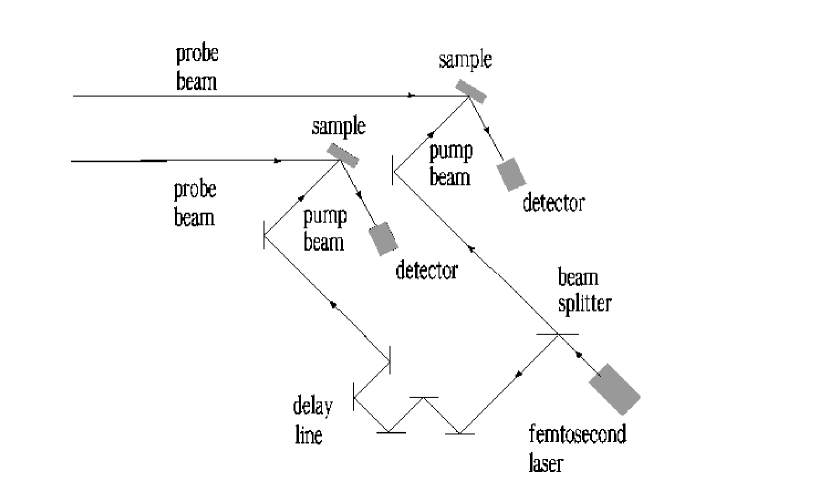
Finally, the lower figure (c) in Fig. 23 shows the advantage of our two-undulator setup when dealing with pump-probe techniques. The production of ultrafast, high power, coherent X-ray pulses is of great importance when it comes to time-resolved experiments, which are used to monitor time-dependent phenomena. In typical pump-probe experiments, a short pump pulse is followed, after a given time, by a short probe pulse. Femtosecond pump-probe capabilities have been available for some years at visible wavelengths. Today there is a strong interest in extending these techniques to the X-ray region: in fact, they enable direct investigation of structural changes with atomic resolution. The synchronization between pump and probe pulses, which should have different wavelengths, remains one of the main technical problems for reaching this kind of pump-probe capabilities. Combination of high-power femtosecond optical pump with femtosecond hard X-ray probe pulses provides a unique tool for the study of ultra-fast phenomena. Light-triggered, time-resolved studies with sub-10 fs resolution obviously require the same level of synchronization between optical and hard X-ray pulses.
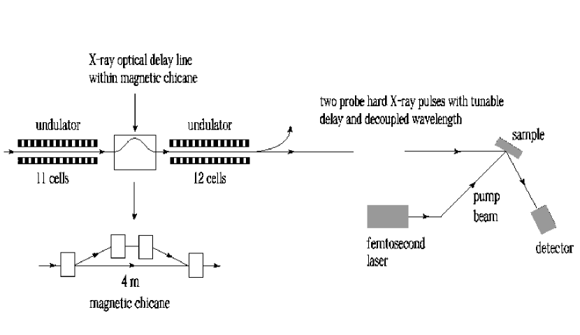
Here we propose a method to get around this obstacle by using an optical pulse as pump and two hard X-ray pulses with tunable delay between them and decoupled wavelengths as probe666Obviously the proposed setup can also be used for hard X-ray pump hard X-ray probe experiments with decoupled wavelengths.. The overall scheme is shown in Fig. 26. Two hard X-ray pulses generated by the same electron bunch from two different parts of the LCLS baseline undulator are delayed with the help of an optical delay line installed within the magnetic chicane. The pulses are tuned to a few percent different resonance wavelengths. Delaying the two hard X-ray pulses with decoupled wavelengths may also be done in the experimental hall with dispersive X-ray optical elements (crystals), but in this case the intensity on the sample becomes weak. This is due to the fact that the SASE radiation has a rather broad bandwidth. As a crystal selects a much smaller bandwidth, most of the photons are discarded. Much larger throughput can be achieved in the situation when the delay is provided in the baseline undulator, since in this case the delay can be generated without dispersive X-ray optics. The idea is to exploit the self-seeding setup, and to install an X-ray mirror chicane within the magnetic chicane. The function of the mirror chicane is to delay the SASE radiation pulse generated in the first part of undulator relatively to the electron bunch and, therefore, also relatively to the second SASE radiation pulse generated downstream of the magnetic chicane, in the second part of the undulator.
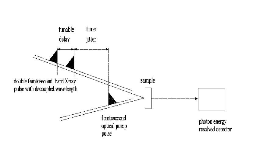
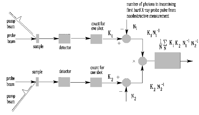
The method exploits the jitter (about fs) between the pump optical pulse and the double hard X-ray probe pulse, and does not require synchronization, Fig. 27. The technique consists in using two separate hard X-ray counters and record counts for each value of the delay between the two probe hard X-ray pulses. The detected photoevents are then correlated, and the sample dynamics is determined from that correlation, Fig. 26. During the light-triggered structural changes, each of the two detectors registers a certain number of photocounts. Let us indicate these numbers with and respectively. We also assume that the shot-to-shot energy fluctuations are small, i.e. within a few percent, which is to be expected given the poor longitudinal coherence of the SASE pulses. and are further normalized to the incomining number of photons in the two radiation pulses. The incoming number of photons can be measured by two nondestructive detectors.
After each shot, the electronics multiplies by , and passes the product to an averaging accumulator, where it is added to the previously stored sum of count products. Finally, the total sum is divided by a number of shots. A tunable delay is introduced between the two probe hard X-ray pulses at the level of the LCLS undulator setup. This can be done with the same X-ray mirrors chicane to be used for the ultrafast X-ray pulse measurement considered above. Therefore, our setup using the self-seeding magnetic chicane for allowing the installation of an X-ray optical delay line can be used for two purposes: for ultrafast X-ray pulse measurements and for optical-pulse pumpdouble hard X-ray pulse probe experiments. The result of the above operations is the (shot to shot) averaged count product , indicating an average over an ensemble of shots. Different shots are characterized by a different jitter. Let us call with the probability of having a certain time delay . Here time zero corresponds to the pump event, so that prior to the pump () one has no signal at all. Therefore we can write
| (23) |
The quantity in Eq. (23) obviously contains information about the signal function. Our method aims to a resolution of a few fs: in fact, we propose to apply it to the study phenomena with characteristic times in the order of a few tens fs. We therefore suppose that the jitter is significantly larger than the characteristic time of the phenomenon under study, at least a few 100 fs. In this case we can assume that the shape of the probability function under the integral is nearly flat, and we can take it out of the integral sign. If we further assume that a percent difference in the energy of the incoming hard X-ray beam has no influence on the signal function777The two pulses have a difference in frequency in the order of a few percent in order to separately record the number of photocounts from the two probe pulses., we can also write , thus obtaining the signal autocorrelation function:
| (24) |
An alternative possibility of post processing of the collected data consists in selecting events characterized by a given value when . This is the case for . Given a certain delay , one has non-zero counts for and zero counts for for , so that in this case the average sum of the counts equals to
| (25) |
In this case, the signal function can be reconstructed from the derivative of Eq. (25) with respect to .
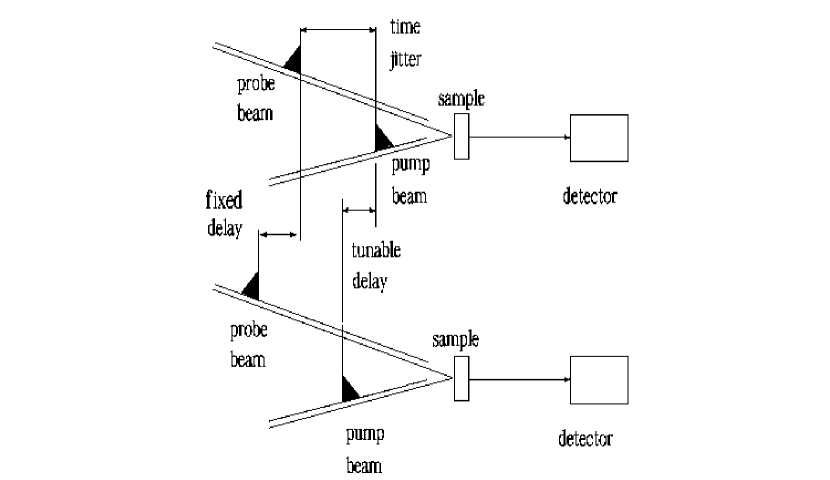
In some experimental situations, the scheme for pump-probe experiments depicted in Fig. 27 is not optimal. A possible technical extension (see Fig. 28 and 29) is to use two spatially separated sets of samples (see Fig. 30), pump and probe pulses and record the correlation of the counts for each value of the delay between two pump pulses . The detected photoevents are than correlated and the sample dynamics is determined from that correlation. The version of the apparatus for measuring the average count product is depicted in Fig. 31. This new approach offers a number of significant advantages. In the scheme in Fig. 27, the wavelength difference between the two pulses cannot be more than a few percent in LCLS baseline case, and this constitutes a significant restriction for the applicability of the method. The spatial separation eliminates the need for different wavelengths in order to separately record the number of counts from the two probe pulses. As a result, possible applications of the scheme in Fig. 29 also cover inelastic scattering experiments.
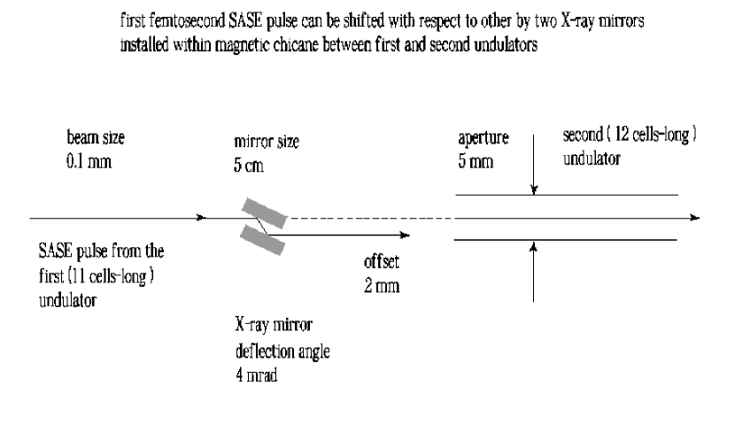
The new experimental setup is sketched in Fig. 28 and Fig. 29. The pump-laser pulse is splitted, delayed and incident on two spatially separated samples. The two SASE pulses, generated by the same electron bunch from two different parts of the baseline undulator, are shifted in transverse direction with the help of X-ray mirrors. The idea is sketched in Fig. 30. The two SASE pulses can be horizontally separated by two mirrors installed within the self-seeding magnetic chicane after the first part of undulator (11-cells long). The horizontal offset can be about mm. Additionally, the mirrors can also be used to generate a few microradians deflection-angle, which is not important within the undulator, but will create further separation of a few millimeters at the position of the experimental station.
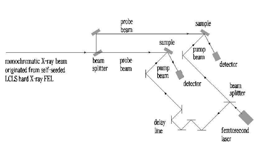
A second possible experimental setup with spatially separated samples is based on the use of an X-ray splitting setup installed in experimental hall (see Fig. 32). High throughput can be achieved when the bandwidth of the X-ray beam is sufficiently small. This scheme makes use of the monochromatic X-ray beam originated from the self-seeded LCLS hard X-ray FEL.
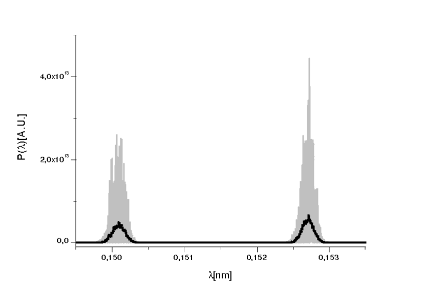
In the previous Section we already performed simulations in the SASE mode for the first 11 cells of the LCLS undulator. The power distribution is shown in Fig. 11. The simulation for the second undulator part consists once more of SASE simulations, where the electron beam is modeled using the values of energy loss and energy spread at the end of the first part. The resonant wavelength is now set, for exemplification purposes, to about nm and nm. The output power distribution and spectrum after 12 cells are shown respectively in Fig. 33 and Fig. 34. A shot-to-shot averaged peak power of about GW is foreseen888If needed, one may increase the output power of the two-color hard X-ray pulses up to ten GW level by application fresh bunch technique. For this, one needs to install an additional magnetic chicane and to use the full number of undulator cells. See our previous paper OUR01 for more details..
8 Conclusions
In this paper we demonstrated that monochromatization of x-ray pulses from XFELs is of great importance in the LCLS upgrade program. In fact, aside for an improvement of brilliance up to two orders of magnitude, a highly monochromatized pulse opens up many other ways to enhance the capacity of the LCLS.
From this standpoint, we demonstrated that monochromatization effectively allows one to use an undulator tapering technique enabling a high-power mode of operation. Monochromatization allows one to use X-ray phase retarders in the experimental hall too, leading with almost no additional costs to full polarization control at the LCLS hard X-ray FEL. In this paper we have also shown how monochromatization enables the use of crystal deflectors in the LCLS X-ray transport system, thus providing the possibility for building new experimental halls (surface structure) for experiments in the hard X-ray wavelength range.
Many other applications of monochromatization for enhancing LCLS capacities may be found. However, in order to keep this paper within reasonable size we did not discuss them here, and we will address them in future publications.
The progress which can be achieved with the methods considered here is based on the novel self-seeding scheme with single crystal monochromators OURX , OURY2 , which is extremely compact and can be straightforwardly realized in the LCLS baseline undulator. The proposed self-seeding setup takes almost no cost and time to be implemented at the LCLS. The LCLS baseline remains the best place for testing our new self-seeding scheme. In its turn, this will allow for a very fast, significant enhance of the LCLS baseline capacity.
9 Acknowledgements
We are grateful to Massimo Altarelli, Reinhard Brinkmann, Serguei Molodtsov for their support and their interest during the compilation of this work. We thank Edgar Weckert for many useful discussions.
References
- [1] P. Emma et al., Nature photonics doi:10.1038/nphoton.2010.176 (2010)
- [2] J. Arthur et al. (Eds.) Linac Coherent Light Source (LCLS). Conceptual Design Report, SLAC-R593, Stanford (2002) (See also http://www-ssrl.slac.stanford.edu/lcls/cdr).
- [3] Y. Ding et al., Phys. Rev. Lett. 102, 254801 (2009).
- [4] M. Altarelli, et al. (Eds.) XFEL, The European X-ray Free-Electron Laser, Technical Design Report, DESY 2006-097, Hamburg (2006).
- [5] T. Tanaka et al. (Eds.) Spring-8 Compact SASE Source Conceptual Design report, Kouto (2005) (See also http://www-xfel.spring8.or.jp/SCSSCDR.pdf)
- [6] J. Feldhaus et al., Optics. Comm. 140, 341 (1997).
- [7] E. Saldin, E. Schneidmiller, Yu. Shvyd’ko and M. Yurkov, NIM A 475 357 (2001).
- [8] E. Saldin, E. Schneidmiller and M. Yurkov, NIM A 445 178 (2000).
- [9] R. Treusch, W. Brefeld, J. Feldhaus and U Hahn, Ann. report 2001 ”The seeding project for the FEL in TTF phase II” (2001).
- [10] A. Marinelli et al., Comparison of HGHG and Self Seeded Scheme for the Production of Narrow Bandwidth FEL Radiation, Proceedings of FEL 2008, MOPPH009, Gyeongju (2008).
- [11] G. Geloni, V. Kocharyan and E. Saldin, ”Scheme for generation of highly monochromatic X-rays from a baseline XFEL undulator”, DESY 10-033 (2010).
- [12] Y. Ding, Z. Huang and R. Ruth, Phys.Rev.ST Accel.Beams, vol. 13, p. 060703 (2010).
- [13] O. Grimm, K. Klose and S. Schreiber, Double-pulse Generation with the FLASH Injector Laser for Pump-Probe Experiments, Proceedings of EPAC 2006, THPCH150, Edimburgh (2006).
- [14] G. Geloni, V. Kocharyan and E. Saldin, ”A simple method for controlling the line width of SASE X-ray FELs”, DESY 10-053 (2010).
- [15] G. Geloni, V. Kocharyan and E. Saldin, ”A Cascade self-seeding scheme with wake monochromator for narrow-bandwidth X-ray FELs”, DESY 10-080 (2010).
- [16] G. Geloni, V. Kocharyan and E. Saldin, ”Scheme for generation of fully coherent, TW power level hard x-ray pulses from baseline undulators at the European XFEL”, DESY 10-108 (2010).
- [17] G. Geloni, V. Kocharyan and E. Saldin, ”Scheme for femtosecond-resolution pump-probe experiments at XFELs with two-color ten GW-level X-ray pulses”, DESY 10-004 (2010).
- [18] G. Geloni, V. Kocharyan and E. Saldin, ”The potential for extending the spectral range accessible to the European XFEL down to 0.05 nm”, DESY 10-005 (2010).
- [19] G. Geloni, V. Kocharyan and E. Saldin, ”Scheme for simultaneous generation of three-color ten GW-level X-ray pulses from baseline XFEL undulator and multi-user distribution system for XFEL laboratory”, DESY 10-006 (2010).
- [20] G. Geloni, V. Kocharyan and E. Saldin, ”Control of the amplification process in baseline XFEL undulator with mechanical SASE switchers”, DESY 10-010 (2010).
- [21] G. Geloni, V. Kocharyan and E. Saldin, ”Ultrafast X-ray pulse measurement method”, DESY 10-008 (2010).
- [22] A. Lin and J.M. Dawson, Phys. Rev. Lett. 42 2172 (1986)
- [23] P. Sprangle, C.M. Tang and W.M. Manheimer, Phys. Rev. Lett. 43 1932 (1979)
- [24] N.M. Kroll, P. Morton and M.N. Rosenbluth, IEEE J. Quantum Electron., QE-17, 1436 (1981)
- [25] T.J. Orzechovski et al., Phys. Rev. Lett. 57, 2172 (1986)
- [26] W. Fawley et al., NIM A 483 (2002) p 537
- [27] M. Cornacchia et al., J. Synchrotron rad. (2004) 11, 227-238
- [28] X. Wang et al., PRL 103, 154801 (2009)
- [29] K. Hirano, T. Ishikawa and S. Kikuta, NIM A 336, 342 (1993).
- [30] J. W. Freeland et al., Rev. of Sci. Intrum. 73, 1408 (2002)
- [31] S. Sasaki, NIM A 331, 763 (1993).
- [32] A. Authier, Dynamical Theory of X-ray diffraction, Oxford University press (2001).
- [33] V. Lucarini et al., Kramers-Kronig relations in optical materials research, Springer, (2004).
- [34] H. A. Kramers, La diffusion de la lumi ere par les atomes, in Atti del Congresso Internazionale dei Fisici, Vol. 2 (Zanichelli, Bologna, 1927), pp. 545 557.
- [35] R. de L. Kronig, On the theory of dispersion of x-rays, J. Opt. Soc. Am. 12, 547 557 (1926).
- [36] J. Toll, Phys. Rev. 104, 6 (1956).
- [37] E. Weckert, Private communication.
- [38] V. Lucarini, http://www.met.reading.ac.uk/ sv901069/software.html
- [39] S Reiche et al., Nucl. Instr. and Meth. A 429, 243 (1999).