11email: fqpotiguar@ufpa.br
From crystal to amorphous: a novel route to unjamming in soft disk packings
Abstract
Numerical studies on the unjamming packing fraction of bi- and polydisperse disk packings, which are generated through compression of a monodisperse crystal, are presented. In bidisperse systems, a fraction up to of the total number of particles have their radii increased by , while the rest has their radii decreased by the same amount. Polydisperse packings are prepared by changing all particle radii according to a uniform distribution in the range . The results indicate that the critical packing fraction is never larger than the value for the initial monodisperse crystal, , and that the lowest value achieved is approximately the one for random close packing. These results are seen as a consequence of the interplay between the increase in small-small particle contacts and the local crystalline order provided by the large-large particle contacts.
pacs:
05.10.-aComputational methods in statistical physics and nonlinear dynamics and 64.70.kjGlasses and 64.70.psGranules1 Introduction
The jammed state of condensed matter is characterized by the sudden arrest of a system’s internal dynamics. Macroscopically, the jammed system develops an yield stress and behaves, essentially, like a solid. A pile of sand under the action of gravity, clogged flow of powders through a pipe or coagulated colloidal microstructures with high elastic moduli are a few examples with practical applications that exhibit jamming. On the theoretical side, random packings of hard and soft elements (spheres, disks, etc.) display similar behavior to those observed in real systems and are often used as prototype systems for the study of jamming. It has been extensively studied recently both by simulations Mak00 ; Her02 ; Her03 ; Zha05 ; Her05 ; Silbert05-01 ; Silbert06 ; Cia09-01 ; Cha09 ; Xu09 and experiments Che09-01 ; Che09-02 . As expected for strongly interacting systems, there are several theoretical proposals Fierro05 ; Henkes05 ; Hentschel07 ; Song08 to describe this state, most of them relying on approximate mean-field arguments.
There are some facts that seem well settled today about jamming. First, a quench is an essential ingredient for a system to reach the jammed state. It prevents any crystallization that may occur during a slow rearrangement of particle positions during equilibration. Second, the critical jamming density is affected by particle size ratio Xu09 , shape Schreck10 and the preparation protocol, but its critical properties are the same (recently, Chaudhuri et al. Cha09 showed that this critical point is not unique, even for large systems). Third, the jamming point in monodisperse and bidisperse packings is manifested in structural properties as the -function behavior of the first peak of the radial distribution function and the split of its second neighbor peak Silbert06 .
Most studies about jamming at zero temperature focus only in one preparation protocol (random packings of, possibly, overlapping particles, quenched to the nearest minimum energy state). One may ask, then, is it possible to produce a jammed state from a completely ordered system (crystal)? Is the quench alone enough to take the packing out of its global minimum of energy and trap it in a jammed state? In particular, if the jammed system prepared in this way will it be more dense than the initial crystal? All these question, and others, will be addressed in this paper. Jammed states will be produced by the quenching, and further decompression, of crystalline disk packings.
This initial condition, at first sight, is not suitable to produce a jammed state, since disordered packings are commonly associated with jamming. However, it will be shown that the structural features of jamming are present in such systems, hence regarding this preparation protocol as a valid one to produce jammed packings. It will be shown that this initial condition opens the possibility to reach jammed states in a distinct region of the packing phase diagram, which are unaccessible from ordinary, random initial packings algorithms. Along with the studies of bidisperse packings, the decompression of polydisperse packings is explored.
2 Simulation methods
The particles are soft, elastic disks, which interact through linear springs. The compression potential energy between disks and given by:
| (1) |
where, is the elastic constant (taken and equal for all contacts), is the -th disk radius, is the distance between the disks, and is the step function.
Initially, the packing consists in disks, of radius (taken as the unit length), arranged in a triangular lattice. The contact energy, eq. (1), is given in units of . The system’s periodic boundary lengths are given by and , where , is the total number of disks. The values are chosen, which gives , throughout the experiments. The results presented here are essentially the same for systems with and . This choice of boundary lengths perfectly accommodates a triangular lattice of equal disks, which implies that the initial packing fraction has the largest value for a two dimensional monodisperse system (the Kepler conjecture) Hal05 :
| (2) |
The quench is performed by changing the disks radii by a suitable amount, the dispersity degree . Such change is instantaneous, in order to trap the system in a jammed state (quench). For bidisperse packings, a number of the disks (randomly chosen) have their radii increased by while the rest of the particles, , have their radii decreased by (similar to what was used in Boc92 ). The number fractions chosen are , , , and . For polydisperse packings, the radii are changed by an amount uniformly distributed between . Fig. 1 shows a quenched configuration.

These changes introduce a compression potential energy, since there will always be some overlap between nearest neighbor grown disks. Given the absence of energy dissipation, the minimization is performed by the conjugate gradient method nr . A dissipative packing cannot be studied with this numerical method. A molecular dynamics (MD) approach is more suitable, and certainly will yield very distinct results (for a study on the phase diagram of dissipative packings see Cia09-02 ). Finally, random packings can also be prepared with a MD approach by swelling void particles (void expansion method Schenker09 ) that increase the volume fraction and takes the system through the jammed point.
It should noticed that a jammed state is not reached, with this protocol, at lower number fraction, for instance . Given the small probability to form large-large contacts at the beginning, the available space for rearrangements is larger than the one needed for complete relaxation. This leads to a melting of the packing, instead of jamming (the highlight emphasizes that the melting picture should be supported by additional simulations). Therefore, such low number fraction packings do not behave as their high counterparts. This will happen only if the mean radius of such packings is larger than .
Since the goal is to find the maximum packing fraction with a vanishing potential energy, an initial minimization is performed right after the quench. The energy minimum is achieved when the difference between the current and the last energy values is no more than . After reaching the nearest energy minimum, particles are slowly decompressed, i.e., particle’s radii are decreased by a small constant amount at each cycle, which provides a slightly larger space for them to relax (expansion step). After each expansion step, an energy minimization is performed in order to take the system closer to the zero potential energy state. The decompression is finished when the total potential energy is less than a predefined value, . Hence, at the of the protocol for a suitable value, the system should be very close to the jamming point. In sect. 3.1, the influence of both parameters on the results will be shown.
The average packing fraction , from now on referred to as the critical packing fraction (CPF), is measured at the end of the decompression as a function of . The averages are over realizations (typically for each case) and the error bars are calculated as in each case. Also, the packing structure and order are studied through the calculation of the Radial Distribution Function (RDF), , and the orientational order parameter:
| (3) |
where the sum runs over the nearest neighbors of disk and is the angle between the line joining the -th and -th disks centers and the axis Sta97 . The absolute value of is measured at the end of the full minimization, and is presented as an average over particles and runs. Its value is unity for a perfect triangular array of particle, while for disordered packings. Two disks are considered first neighbors if they overlap.
3 Results and discussion
This sect. holds all numerical results. First, some results for the CPF as a function of the simulation parameters and are shown. Second, the full CPF results, along with the packing structure and order will follow, respectively.
3.1 Independence on the simulation parameters
The simulation is controlled by two sensitive parameters, the decompression rate, , and the minimum compression energy, . Figure 2 holds the results for the CPF for three distinct parameter sets:
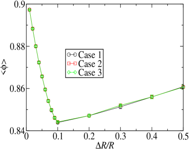
The three cases presented, all for , have the following set of parameter values: case 1, and ; case 2, and ; case 3, and . As seen in this figure, all results agree well within simulation error. Hence, all the following results will be given for case 1, unless noticed otherwise. This value of corresponds to a minimum energy per particle of the order . Similar results hold for the polydisperse packing (not shown).
3.2 Jamming packing fraction
In fig. 3, the results for the CPF for all number fraction, , and size dispersity, , values are shown.
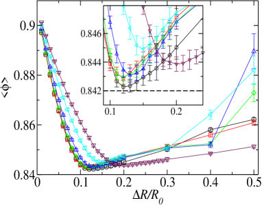
From this graph, one can see that the final packing fraction is never larger than the one for the triangular lattice, eq. (2), and it goes through a minimum. From the inset of fig. 3, it can be seen that the minimum CPF changes with number fraction. Its lowest value is for at , while the largest minimum is for at . The CPF value for the random close packing (RCP) state is shown as a reference value, since it is the jamming packing fraction for the monodisperse packing Her02 . These results indicate that the RCP state corresponds to the lowest critical packing fraction achieved with this protocol, with packing properties distinct from the original study (in that case Her02 , and ). For the polydisperse packing, the minimum CPF is at .
Recent results on jamming of bidisperse sphere packings Xu09 and ellipsoid and dimer packings Schreck10 , that focused on the influence of the size ratio in the CPF, show that this quantity presents a maximum in the size ratio range . These references also carried out their simulations with random initial packings. (In Xu09 , the largest CPF occurs at and ). Here, all CPF values are also above the RCP one, but it goes through a minimum instead of a maximum. The reason behind this distinction seems to be mainly the initial packing. The jamming point in a random monodisperse packing may be increased with an appropriate size ratio (the system packs more efficiently). On the other hand, the jamming point for a regular packing can only be decreased from the value given in eq. (2). This can be seen as a consequence of the fact that, as stated earlier, the triangular lattice is the most dense packing of equal disks Hal05 . Therefore, one can conclude that performing a decompression simulation with a regular initial packing, one can reach a very dense jammed state, not accessible from a random initial packing. This is the main results of this paper and it is what is meant by a novel route to unjamming in the title.
The small dispersity behavior of the CPF can be understood as follows. When the regular triangular array of disks is quenched, the total area occupied by the disks, initially given by , is changed to:
where represents the total overlapped area. Developing the squared terms and using the fact that , one reaches the following expression for the initial modified area:
Since the experiment is carried through particle decompression at a constant rate, when the overlapped area vanishes, the total area occupied by the disks should be given by the exact same expression, but for a distinct mean radius , instead of :
The value of this mean radius is , with , where is the number of decompression steps. Defining and , and dividing both sides by one has:
The final average CPF, among different experiments with fixed boundary lengths can be obtained using the average value in . Therefore, using eq. (2), this relationship yields:
| (4) |
A similar argument holds for a polydisperse packing. In this case, the area occupied by the disks after the initial compression is given by:
where is the change in the -th disk radius. At the end of the decompression phase, the total disk area is:
with given as above. Since the quantity is uniformly distributed in the range , one may use the moments of ,
| (5) | |||
| (6) |
to write
Following the same steps as in the bidisperse case, the average CPF can be written as:
| (7) |
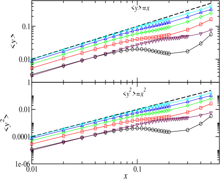
Hence, with the knowledge of the average number of decompression steps, one can match equations (4) and (7) with the results given in fig. 3. The results for and are given in fig. 4.
Consider the following argument to explain this result.
If this decompression experiment was performed in the
monodisperse case, where each disk has exactly contacts, simetrically
placed around its center, no change in the structure will ever occur due to
the decompression, and the packing fraction value in which the
compression energy is zero would be given by (2). Therefore, the
disk radii should return to their original value in order to reach this packing
fraction. This implies that . Since at
low dispersity this relationship is approximately realized, one can infer that
at the jamming point, one has and
.
These four parameters represent the effect of structure
rearrangements in the quantity . Table 1 holds their values as
measured from power law fits to the curves in fig. 4. Since
deviation from power law behavior do not occur at the same dispersity for all
cases, the fits were performed up to for , for
, for and for the other cases. The
parameters approach their monodisperse values as one
increases the number fraction. The polydisperse packing is an exception since
it has no monodisperse limit. Also, one can see that, at all number fractions
and the polydisperse case, the relationship holds. The data
do not imply a simple relationship between the coefficients and .
| poly | ||||||
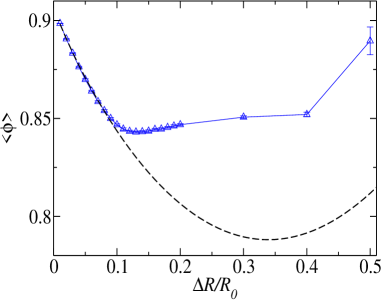
By using this form for the average number of decompression steps, the average CPF, eq. (4), can be cast in the following form:
| (8) |
This curve for the parameters , , and given for the case is shown as a dashed line in fig. 5. One can see that, at low dispersity, this eq. agrees well with the results.
For the polydisperse packing, the average CPF can be written as:
| (9) |
The comparison between figs. 3 and 4 shows that the deviation from the power law behavior of coincides with the region where the CPF reaches its minimum value. Since a complete understanding of this fact would be given by a more detailed (and complicated) theoretical approach, such as the one proposed in Song08 , only the packing structure is probed here. The reason behind this choice is that the structure relaxation during decompression is the main cause for the results seen in figs. 3 and 4.
3.3 Packing structure
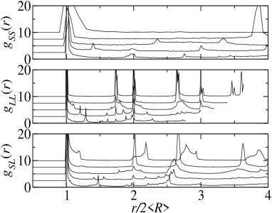
The RDF is measured at the end of the full minimization process. These measurements are performed regarding the type of particle contact, i.e., the probabilities of small-small, , large-large, , and small-large, , contacts are measured. In the triangular array of monodisperse disks, one expects to have sharp peaks at , and particle diameters. Figure 6 shows all RDFs for and all number fractions. Figure 7 has these same functions but for a dispersity value of . In both cases, all interparticle distances are normalized by the corresponding final average particle diameter. For instance, for a small-small contact, the final small particle diameter is , where is the average number of decompression steps, fig. 4. Hence, the distance range where these contact probabilities are measured appear distinct for each contact type and number fraction, especially for large-large contacts, which have a larger mean particle diameter.
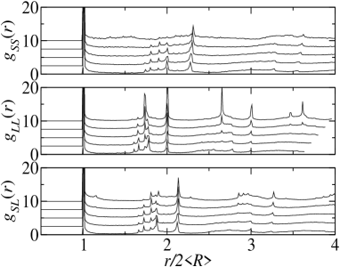
In all curves in fig. 6, the jamming structural signature, a delta-like first peak and a split second peak, are seen. Also, the second small-small contact peaks are not located precisely at and . Instead, they are shifted to the right, consistent with the results shown in Xu09 . A brief explanation of this fact is that these two peaks occur only when three particles form a triangular cluster. Hence, this type of cluster should be absent for small-small and small-large contacts. Moreover, small-large contacts have a second peak at intermediate positions between small-small and large-large contacts, as expected, since the mean diameter of such a contact is given by .
A marked feature of these graphs is that the and peaks between and decrease with , while those for become sharper. This indicates that, for larger , small particle relax to positions farther away from each other, even though they start all at the same structure.
The peaks at , and , increase and become sharper, while the intermediate ones between and almost disappear at the largest number fraction. Since sharp peaks at and are a signature of a triangular lattice structure, one may infer that such large particle rich packings relax to structures similar to a crystalline one. This fact also explains why the large-large peaks between and become smaller. Such characteristic should be expected, since the initial packing is regular and only large-large particle contacts, at the outset, imply compression. Therefore, if a group of first neighbors become large particles, they will probably remain in this cluster up to the end of the process.
An illustration of such a configuration is given in fig. 8. It shows a well mixed packing with an occasional pocket of large particle crystals (lower left corner).

On the other hand, the pair correlation functions at large dispersity, fig. 7, shows markedly distinct features of the packing structure. First of all, small particle aggregates become progressively more distant, in small particle mean diameter units, for larger . Second, at and shows several small peaks between those at and , as in fig. 6, but the one at is not easy to distinguish. Only at high number fractions this peak becomes clear. This means that large particles form, again, structures close to crystalline ones at high number fraction. Finally, one can see a clear change in from to . The peaks for the lower number fraction are sharper than the corresponding ones at larger number fraction. This is probably due to the fact that small particles can be more easily accommodated in vacancies among the large particle contact network (approximately triangular). Figure 9 shows a snapshot of a packing at the largest number fraction and dispersity. One clearly sees that the structure is a crystal with defects. Finally, the broad peak around , at , does not imply overlap between small particles. In fact, the value is zero while . The reason for this apparent broad peak is that the bin size is larger for smaller average contact diameter. This quantity decreases for increasing number fraction and dispersity. Hence, the bin size at is significantly larger than those at lower number fractions.

Although not seen in the RDF plots, the area below the first peak for all RDFs changes as a function of the number fraction and dispersity. This might have implications for the mechanism that leads to the CPF values seen in fig. 3. In order to study this influence, the area below the first peak, in each of the RDFs, is measured. The range in which this area is considered is from the first peak position (contact diameter) up to this distance plus the dispersity, . This is an (unnormalized) account for the average number of neighbors of a given type around a given particle Silbert06 . A more natural approach to this question would be to compare the coordination numbers with regard to each contact type. Any protocol for producing jammed states is known to produce an amount of rattlers (particles with no contacts). These particles also contribute to the packing relaxation. Then, a comparison of coordination number would exclude these particles from the analysis. The notation corresponds to
This choice for the integration limits ensures that, for small-small contacts, only small particles are within this range. At the first few dispersity values, which are of the order of the bin size, this integration leads to an overestimation of the number of neighbors.
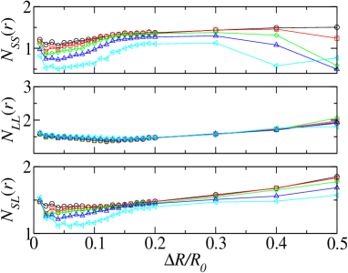
One can directly infer that up to intermediate dispersities, where the critical packing fraction reaches its lowest value, small particles increase their probability of being around other particles, of both types (top and bottom panels) with a more pronounced effect at , while the probability for large-large particle contacts reaches its lowest value (middle panel). In addition to that, the large-large contacts barely change with number fraction and its minimum value occurs at a dispersity value close to those of the minimum jamming density, fig. 3.
These results, along with the RDFs in figs. 6 and 7, imply that, less efficient packing correspond to more small particle clusters and less large particle ones. A possible explanation can be given by the fact that the initial compression is provided solely by large particles and the packing relaxation should take the available space provided by small-small neighbors, i.e., large particles should push small ones in order to decrease the potential energy. This will deform the initial structure and small-small contacts will be formed in a distinct structure that the initial one. Since this structure is the most dense possible, the critical packing will occur at a lower density. Also, the larger the number of small particle contacts, the larger is the space available for structure rearrangements. Therefore, less decompression cycles will be needed to reach the minimum energy.
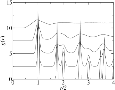
For polydisperse packings, the jammed structure shows a completely distinct scenario. Since there are several particle sizes, the chance for the formation of crystalline regions during the packing relaxation is very low. Therefore, the packing structure should be strongly amorphous, as shown in fig. 11, at large . Moreover, this amorphization seems to be a continuous process, since the peaks at low dispersity become smoother for larger until they merge and, eventually, disappear.
Since the results for the RDFs implied that the small particle contacts introduced disorder, one can find a correlation between the CPF and the contacts orientational order. Fig. 12 has the average value, over particles and runs, measured at the end of the decompression, of the orientational order parameter related to the triangular lattice, eq. (3). It should be noticed that, given the definition of first neighbors followed here, this order parameter does not contain any contribution from rattlers.
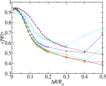
First of all, one see that, at low dispersity, this order parameter decreases continuously. This is consistent with the arguments given earlier, that small particle contacts introduce disorder in the system and it packs less efficiently. Moreover, the fast increase of the critical packing fraction at large dispersities and number fractions can be seen to correlate with a fast increase in the orientational order, also consistent with the appearance of large crystalline regions. On the other hand, the smooth increase in with dispersity is not accompanied with a corresponding increase in the order parameter. This implies that the inversion in the CPF curves are due to pockets of large particle clusters, as seen in fig. 10 (middle panel), regardless of the overall decrease in order. Large particles clusters have a high value of , and, given the smooth increase in with dispersity, one may infer that their number is small, since the whole system has a low value of the order parameter. Only when large particle clusters are formed, the global order increases, providing a more dense packing.
In the polydisperse case, the orientational order parameter continuously decreases with increasing dispersity. Its value is higher than for the bidisperse cases up to . This is surprising for one would expect that more particle sizes would lead to less order (from eqs. (5 and (6)) one can see that the size dispersion of a polydisperse packing is proportion to ). Given that there is no monodisperse limit for this packing when , one can imagine that the order parameter for the and cases will eventually be higher than the polydisperse one at some dispersity beyond .
4 Summary and conclusions
It was presented a numerical study on the jamming properties and structure of a two dimensional packing of elastic disks, for bi- and polydisperse cases. The attention was focused on the value of the maximal packing fraction for which the compression energy is zero. This was measured through numerical decompression experiments of a disordered packing, initially arranged in a crystal (triangular lattice) structure. The critical packing fraction (CPF) was measured at the end of the decompression and was shown as a function of the dispersity degree, . Also, for bidisperse packings, the CPF was also studied as a function of the number fraction of large disks.
The general trend of the CPF is initially decreasing up to a minimum value, and then increasing with dispersity, fig. 3. The lowest CPF value is close to the RCP value, but obtained for a number fraction of , instead of the original value obtained at Her02 . The distinct CPF behavior with observed in Xu09 ; Schreck10 is due to the fact that, in the present case, one starts from the most possible dense packing and, therefore, the introduction of disorder, through the quench and internal structure rearrangement, will certainly lead to a lower jamming packing fraction, since a more efficient packing can be achieved with a increase in local order Tor00 .
At low dispersity, the system behaves approximately as the monodisperse crystal, as seen in the results for the average number of decompression steps, fig. 4. The departure from the monodisperse regime can be attributed to an increase in the number of small-small particle contacts, fig. 10.
The structure reveals that, for low dispersity, the decompressed packing has significant order, as revealed by the long range behavior of , and . The packing structure is mostly disordered at intermediate dispersities, and at the highest dispersity, large-large particle contacts bear most of the translational order in the system, which forms a crystal with defects, with the few small particles scattered between the scarce space available between the large particle contacts.
For polydisperse packings the long range order is completely absent for large dispersities, since a disk size is chosen from a uniform distribution of values in the range , for larger , there will a very broad distribution of particle sizes.
The data for the local orientational order gives a similar picture. For larger number fractions, the packings are more ordered locally compared to lower number fraction cases. Also, for low dispersities, the packing is more ordered, as expected since it behaves like the monodisperse one. Above the low dispersity range, the local orientational order decreases with , regardless of the smooth increase in the CPF. However, the fast increase of the CPF at large number fraction and dispersities is strongly correlated with a fast increase in this order parameter, implying that such packings are close to a crystal.
Acknowledgements
I thank C. Brito for a very welcome reading of this paper. This work is financially supported by CNPq and FAPESPA.
References
- (1) H. A. Makse, D. L. Johnson and L. M. Schwartz, Phys. Rev. Lett. 84, 4160 (2000).
- (2) C. S. O’Hern, S. A. Langer, A. J. Liu and S. R. Nagel, Phys. Rev. Lett. 88, 075507 (2002).
- (3) C. S. O’Hern, L. E. Silbert, A. J. Liu and S. R. Nagel, Phys. Rev. E 68, 011306 (2003).
- (4) H. P. Zhang and H. A. Makse, Phys. Rev. E 72, 011301 (2005).
- (5) N. Xu, J. Blawzdziewicz and C. S. O’Hern, Phys. Rev. E 71, 061306 (2005).
- (6) L. E. Silbert, A. J. Liu and S. R. Nagel, Phys. Rev. Lett. 95, 098301 (2005).
- (7) L. E. Silbert, A. J. Liu and S. R. Nagel, Phys. Rev. E 73, 041304 (2006).
- (8) M. P. Camarra and A. Coniglio, Phys. Rev. Lett. 103, 235701 (2009).
- (9) P. Chaudhuri, L. Berthier and S. Sastry, cond-mat.stat-mech/0910.0364v2.
- (10) N. Xu and E. S. C. Ching, Soft Matter 6, 2944 (2010).
- (11) X. Cheng, Phys. Rev. E 81, 031301 (2010).
- (12) X. Cheng, Soft Matter 6, 2931 (2010).
- (13) A. Fierro, M. Nicodemi, M. Tarzia, A. de Candia and A. Coniglio, Phys. Rev. E 71, 061305 (2005).
- (14) S. Henkes and B. Chakraborty, Phys. Rev. Lett. 95, 198002 (2005).
- (15) H. G. E. Hentschel, V. Ilyin, N. Makedonska, I. Procaccia and N. Schupper, Phys. Rev. E 75, 050404(R) (2007).
- (16) C. Song, P. Wang and H. A. Makse, Nature 453, 629 (2008).
- (17) C. F. Schreck, N. Xu and C. S. O’Hern, Soft Matter 6, 2960.
- (18) T. C. Hales, Annals of Mathematics 162, 1062 (2005).
- (19) L. Bocquet, J.-P. Hansen, T. Biben and P. Madden, J. Phys.: Cond. Matt. 4, 2375 (1992).
- (20) W. H. Press, B. P. Flannery, S. A. Teukolsky and W. T. Vetterling, Numerical Recipes in C, 2nd edition (Cambridge University Press, Cambridge, 1986).
- (21) M. Pica Ciamarra, R. Pastore, M. Nicodemi and A. Coniglio, cond-mat.soft:0912.3140.
- (22) F. Schenker, F. T. Filser, H. J. Herrmann and L. J. Gauckler, Granular Matter 11, 201 (2009).
- (23) M. R. Sadr-Lahijany, P. Ray, H. E. Stanley, Phys. Rev. Lett. 79, 3206 (1997).
- (24) S. Torquato, T. M. Truskett and P. G. Debenedetti, Phys. Rev. Lett. 84, 2064 (2000).