Flows and heterogeneities with a vane tool: MRI measurements
Synopsis
We study the local flow properties of various materials in a vane-in-cup geometry. We use MRI techniques to measure velocities and particle concentrations in flowing Newtonian fluid, yield stress fluid, and in a concentrated suspension of noncolloidal particles in a yield stress fluid. In the Newtonian fluid, we observe that the -averaged strain rate component decreases as the inverse squared radius in the gap, in agreement with a Couette analogy. This allows direct comparison (without end-effect corrections) of the resistances to shear in vane and Couette geometries. Here, the mean shear stress in the vane-in-cup geometry is slightly lower than in a Couette cell of same dimensions, and a little higher than when the vane is embedded in an infinite medium. We also observe that the flow enters deeply the region between the blades, leading to significant extensional flow. In the yield stress fluid, in contrast with the usually accepted picture based on simulation results from the literature, we find that the layer of material that is sheared near the blades at low velocity is not cylindrical. There is thus a significant extensional component of shear that should be taken into account in the analysis. Finally and surprisingly, in the suspension, we observe that a thin non-cylindrical slip layer made of the pure interstitial yield stress fluid appears quickly at the interface between the sheared material and the material that moves as a rigid body between the blades. This feature can be attributed to the non-symmetric trajectories of the noncolloidal particles around the edges of the blades. This new important observation is in sharp contradiction with the common belief that the vane tool prevents slippage, and may preclude the use of the vane tool for studying the flows of pasty materials with large particles.
I Introduction
Experimental investigations of the rheology of concentrated suspensions often involve a vane-in-cup geometry (see Barnes and Nguyen (2001) for a review). The vane tool offers two main advantages over other geometries. First, it allows the study of the properties of structured materials with minimal disturbance of the material structure during the insertion of the tool [Dzuy and Boger (1983); Alderman et al. (1991)]. It is thus widely used to study the properties of gels and thixotropic materials [Alderman et al. (1991); Stokes and Telford (2004)] and for in situ study of materials as e.g. in the context of soil mechanics [Richards (1988)]. Second, it is supposed to avoid wall slip [Keentok (1982); Dzuy and Boger (1983); Saak et al. (2001)], which is a critical feature in concentrated suspensions [Coussot (2005)]; the reason for this belief is that the material sheared in the gap of the geometry is sheared by the (same) material that is trapped between the blades. Consequently, it is widely used to study the behavior of pasty materials containing large particles, such as fresh concrete [Koehler et al. (2006); Estellé et al. (2008); Wallevik (2008); Jau and Yang (2010)] and foodstuff [Stokes and Telford (2004); Martínez-Padilla and Rivera-Vargas (2006)].
The constitutive law of materials can be obtained from a rheological study with the vane-in-cup geometry provided one knows the coefficients – called “geometry factors” – that allow the conversion of the raw macroscopic data (torque, rotational angle or velocity) into local data (shear stress, shear strain or shear rate). However, in contrast with other classical geometries, even the a priori simple linear problem (for Hookean or Newtonian materials) is complex to solve with a vane tool. This linear problem was studied theoretically by Sherwood and Meeten (1991) and Atkinson and Sherwood (1992) in the general case of a -bladed vane tool embedded in an infinite linear medium. The analytical expression found for the torque vs. rotational velocity is in rather good agreement with macroscopic experimental data [Sherwood and Meeten (1991)]. Note however two possible shortcomings of this theoretical approach for its use in practice: the blades are infinitely thin and there is no external cylinder.
There is no such approach in the case of nonlinear media (i.e. complex fluids). A practical method used to study the flow properties of non-linear materials, known as the Couette analogy [Bousmina et al. (1999); Aït-Kadi et al. (2002); Estellé et al. (2008)], consists in calibrating the geometry factors with Hookean or Newtonian materials. One defines the equivalent inner radius of the vane-in-cup geometry as the radius of the inner cylinder of a Couette geometry that would have the same geometry factors for a linear material. For any material, all macroscopic data are then analyzed as if the material was sheared in a Couette geometry of inner cylinder radius . The nonlinearity (that affects the flow field) is sometimes accounted for as it is in a standard Couette geometry [Estellé et al. (2008)]. This approach may finally provide constitutive law measurements within a good approximation [Baravian et al. (2002)].
However, simulations and observations show that is not a universal parameter of the vane tool independent of the properties of the studied material. While the streamlines go into the virtual cylinder delimited by the blades in the case of Newtonian media [Baravian et al. (2002)], yielding an equivalent radius lower than the vane radius [Sherwood and Meeten (1991); Atkinson and Sherwood (1992)], it was found from simulations [Barnes and Carnali (1990); Savarmand et al. (2007)] that the streamlines are nearly cylindrical everywhere for shear-thinning fluids if their index is of order 0.5 or less, and thus that in these cases. Moreover, for yield stress fluids, simulations and photographs of the shearing zone around a four-bladed vane rotating in Bingham fluids [Keentok et al. (1985)], simulations of Herschel-Bulkley and Casson fluids flows in a four-bladed vane-in-cup geometry [Yan and James (1997)], and simulations of Bingham fluids flows in a six-bladed vane-in-cup geometry [Savarmand et al. (2007)], all show that at yield (i.e. at low shear rates), the material contained in the virtual cylinder delimited by the blades rotates as a rigid body, and that it flows uniformly in a thin cylindrical layer near the blades. This is now widely accepted [Barnes and Nguyen (2001)] and used to perform a Couette analogy with ; the yield stress is then simply extracted from torque measurements at low velocity thanks to , where is the vane tool height (neglecting end effects) [Nguyen and Boger (1992)].
The flow field in a vane-in-cup geometry and its consequences on the geometry factors have thus led to many studies. However, only theoretical calculations, macroscopic measurements and simulation data exist in the literature: there are no experimental local measurements of the flow properties of Newtonian and non-Newtonian materials induced by a vane tool except the qualitative visualization of streamlines made by Baravian et al. (2002) for Newtonian media, and the photographs of Keentok et al. (1985) for yield stress fluids. Moreover, while the main advantage of the vane tool is the postulated absence of wall slip, as far as we know, this widely accepted hypothesis has been neither investigated in depth nor criticized. In order to provide such local data, we have performed velocity measurements during the flows of a Newtonian medium and of a yield stress fluid in both a coaxial cylinder geometry and a vane-in-cup geometry. We have also performed particle concentration measurements in a concentrated suspension of noncolloidal particles in a yield stress fluid, which is a good model system for complex pastes such as fresh concrete [Mahaut et al. (2008a, b)]. Our main results are that:
-
(i)
in the Newtonian fluid, the -averaged strain rate component decreases as the inverse squared radius in the gap, as in a Couette geometry, which allows direct determination (without end-effect corrections) of the value of : it is here found to be lower than , but slightly higher than for a vane in an infinite medium; the flow enters deeply the region between the blades, leading to a significant extensional flow;
-
(ii)
in the yield stress fluid, in contrast with results from the literature, the layer of material that is sheared near the blades at low velocity does not have a cylindrical shape;
-
(iii)
in the suspension of noncolloidal particles in a yield stress fluid, the noncolloidal particles are quickly expelled from a thin zone near the blades, leading to the development of a thin slip layer made of the pure interstitial yield stress fluid, in sharp contradiction with the common belief that the vane tool prevents slippage.
In Sec. II, we present the materials employed and the experimental setup. We present the experimental results in Sec. III: velocity profiles obtained with a Newtonian oil and with a yield stress fluid are presented in Sec. IIIA and Sec. IIIB, while Sec. IIIC is devoted to the case of suspensions, with a focus on the slip layer created by a shear-induced migration phenomenon specific to the vane tool.
Throughout this paper, we use cylindrical coordinates . All flows are supposed to be invariants (i.e. there are no flow instabilities). We define the -average of a function as .
II Materials and methods
A Materials
We study three materials: a Newtonian fluid, a yield stress fluid,
and a concentrated suspension of noncolloidal particles in
this yield stress fluid.
The Newtonian fluid is a silicon oil of 20 mPa.s viscosity.
The yield stress fluid is a concentrated water in oil emulsion.
The continuous phase is dodecane oil in which Span 80 emulsifier
is dispersed at a 7% concentration. A 100 g/l CaCl2 solution
is then dispersed in the oil phase at 6000 rpm during 1 hour with
a Sliverson L4RT mixer. The droplets have a size of order 1 m
from microscope observations. The droplet concentration is 75%,
and the emulsion density is g cm-3. The
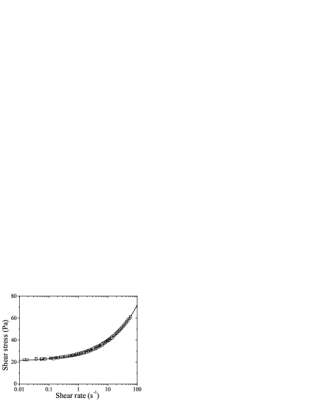
emulsion behavior, measured through coupled rheological and MRI
techniques described in Ovarlez et al. (2008) (see
Fig. 1), is well fitted to a
Herschel-Bulkley behavior with
yield stress
Pa, consistency =6.8 Pa s0.44, and index .
The suspension is a suspension of monodisperse polystyrene beads (density g cm-3, diameter m) suspended at a 40 volume fraction in the concentrated emulsion described above. The density matching between the particles and the yield stress fluid is sufficient to prevent shear-induced sedimentation of the particles in the yield stress fluid [Ovarlez et al. (2010)]; in all experiments, we check that the material remains homogeneous in the vertical direction by means of MRI density measurements.
B Rheometry
The rheometric experiments are mainly performed within a
six-bladed vane-in-cup geometry (vane radius cm, outer
cylinder radius cm, height 11 cm). The shaft radius is
1.1 cm and the blade thickness is 6 mm. Other experiments are
performed with a wide-gap Couette geometry of slightly different
inner cylinder radius cm, due to the presence of
sandpaper (the other dimensions were identical). The inner
cylinder of the Couette geometry, and the outer cylinder of both
geometries are covered with sandpaper of roughness equivalent to
the size of the largest
elements of the materials studied in order to avoid wall slip.
In the rheometric experiments presented here, we control the
rotational velocity of the inner cylinder, with values ranging
from 0.1 to 100 rpm.
C MRI
Proton MRI [Callaghan (1991)] was chosen as a non-intrusive technique in order to get measurements of the local velocity and of the local bead concentration inside the sample. Experiments are performed on a Bruker 24/80 DBX spectrometer equipped with a 0.5T vertical superconductive magnet with 40 cm bore diameter and operating at 21 MHz (proton frequency). We perform our experiments with a home made NMR-compliant rheometer, equipped with the geometries described in the previous section. This device was already used in a number of previous rheo-nmr studies [Raynaud et al. (2002); Rodts et al. (2004); Ovarlez et al. (2006)], and is fully described in Raynaud et al. (2002). The volume imaged is a (virtual) rectangular portion of 4 cm in the axial (vertical) direction with a width (in the tangential direction) of 1 cm and a length of 7 cm (in the radial direction, starting from the central axis). Velocity and concentration profiles and , averaged over the vertical and tangential directions in this volume, are obtained with a resolution of 270 m in the radial direction. This volume is situated at the magnet center (so as to minimize the effects of field heterogeneities) and sufficiently far from the bottom and the free surface of the rheometer so that flow perturbations due to edge effects are negligible. We checked that the velocity and concentration profiles are homogeneous along the vertical direction in this volume, which justifies averaging data over this direction.
Details on the sequence used to obtain velocity profiles can be found in [Raynaud et al. (2002); Rodts et al. (2004)]. While it is possible to get 2D or 3D maps of 2D or 3D velocity vectors [Rodts et al. (2004)], such measurements may actually take minutes and require complex synchronization of the MRI sequences and of the geometry position. However, we will show in the following that the azimuthal velocity alone provides a valuable information that can be sufficient for most analyses; in particular it allows computation of the -averaged strain rate component and thus the -averaged shear stress (and the torque ) in the case of the Newtonian oil. That is why we have chosen to limit ourselves to 1D profiles of 1D velocity measurements, namely the azimuthal velocity as a function of the radius and time , for which a single measurement may take as little as 1 s; this has allowed us to perform a sufficient number of experiments, with various materials, geometries, and rotational velocities. Depending on the time over which this measurement is averaged as compared to where is the number of blades and is the rotational velocity, this measurement may provide either a time (or )-averaged azimuthal velocity or an instantaneous (transient) azimuthal velocity . In this latter case, the dependence of the azimuthal velocity at a given radius can then be easily reconstructed by simply replacing the time dependence by an angular dependence with . It should also be noted that due to incompressibility of the materials we study, the field can be reconstructed thanks to with ; however, this derivation from the experimentally measured values of cannot be very accurate. Finally, from and , we are also able to evaluate the strain rate components and . Note that the derivative with respect to coordinate of experimental data measured at regularly spaced positions was computed as: .
The NMR sequence used in this work to measure the local bead concentration is a modified version of the sequence aiming at measuring velocity profiles along one diameter in Couette geometry [Hanlon et al. (1998); Raynaud et al. (2002)], and is described in full detail in Ovarlez et al. (2006). The basic idea is that during measurements, only NMR signal originating from those hydrogen nuclei belonging to the liquid phase of the sample (i.e. both the oil and water phase of the emulsions) is recorded: the local NMR signal that is measured is thus proportional to , where is the local particle volume fraction. A rather low absolute uncertainty of on the concentration measurements values was estimated in Ovarlez et al. (2006). All volume fraction profiles are measured at rest, after a given flow history. This is possible because the particles do not settle in the yield stress fluid at rest: the volume fraction profile induced by shear is gelled by the interstitial yield stress fluid.
III Experimental results
In this section, we study successively the flow properties of the Newtonian oil, the yield stress fluid, and the suspension.
A Newtonian fluids
In this section, we study the flows observed with a Newtonian fluid. We first present a basic theoretical analysis of the flows in a vane-in-cup geometry as compared to flows in a standard Couette geometry, which provides the basis for a Couette analogy. The -averaged azimuthal profiles are then shown, and are compared to predictions of the Couette analogy. The full velocity field , is finally presented and analyzed.
1 Couette analogy: theoretical analysis
The stress balance equation projected along the azimuthal axis is:
| (1) |
where is the deviatoric stress tensor and the pressure.
The strain rate tensor component is given by:
| (2) |
We recall that the constitutive law of a Newtonian fluid of viscosity is:
| (3) |
.
In all the following analysis, we assume a no-slip boundary condition at the walls of the inner tool and of the cup.
Couette geometry
In a standard – coaxial cylinders – Couette geometry, due to cylindrical symmetry, Eq. 1 becomes which means that the whole shear stress distribution in the gap is known whatever the constitutive law of the material is. If a torque is exerted on the inner cylinder driven at a rotational velocity , is given by:
| (4) |
For a Newtonian fluid of viscosity , it follows that the strain rate component is given by:
| (5) |
As Eq. 2 becomes with cylindrical symmetry, due to the boundary conditions and , from , one gets alternatively . This yields the following azimuthal velocity profile:
| (6) |
Finally, the viscosity of a Newtonian fluid is obtained from the measured torque/rotational velocity relationship through
| (7) |
These equations will be used for the comparison with the flows observed in a vane-in-cup geometry, in particular to determine the radius of the equivalent Couette geometry.
Vane-in-cup geometry
In a vane-in-cup geometry, there is a priori no cylindrical symmetry and all quantities a priori depend on . However, averaging Eq. 1 over yields . This means that what is true in a Couette geometry, , is still true on average with a vane-in-cup geometry: independently of the material’s constitutive law. Note that this derivation is true only between and ; this is not true for the material between the blades as the unknown distribution in the blades contributes to the -average. The link between this stress distribution and the torque exerted on the vane tool may then seem difficult to build. However, it can be equivalently computed on the outer cylinder as . This means that Eq. 4 is still valid for the -averaged shear stress in the vane-in-cup geometry, for :
| (8) |
From the -averaged Eq. 3, this means that the -averaged strain rate distribution in a Newtonian fluid, for , is:
| (9) |
From the -averaged Eq. 2 , this means that the -averaged azimuthal velocity profile of a Newtonian fluid of viscosity in a vane-in-cup geometry for , with a boundary condition is given by:
| (10) |
Finally, the only difference with a standard Couette flow, as regards these -averaged quantities, is that we do not know the value of ; we only know that , for integer, where is the number of blades. This means that and follow the same scaling with and as in the standard Couette geometry, but with a different prefactor.
Nevertheless, these equations provide a new insight in the Couette analogy. The usual way of performing the Couette analogy consists in defining the radius of the equivalent Couette geometry as the radius that allows measuring the viscosity of a Newtonian fluid with the standard Couette formula. From Eq. 7, should then be correctly obtained from the torque/rotational velocity relationship measured in a vane-in-cup geometry with:
| (11) |
From Eqs. 7 and 11, it means in particular that the torque exerted by the vane tool is decreased by a factor
| (12) |
as compared to the torque exerted by the inner cylinder of a Couette geometry of same radius at a same rotational velocity.
Here, from Eqs. 10 and 6, we see that from the local flow perspective, there is a Couette analogy in the sense that the -averaged azimuthal velocity (and shear) profiles will be exactly the same as in a Couette geometry. This defines a radius of the equivalent Couette geometry, such that and for are given by:
| (13) | |||
| (14) |
Of course, these two definitions of are equivalent: combining Eqs. 10 and 11 yields Eq. 13.
This point of view provides an additional meaning to the Couette analogy, namely the similarity of the average flows, and offers a new experimental mean to determine , which is more accurate than calibration. In rheological measurements, the relationship has to be corrected for end effects [Sherwood and Meeten (1991); Martínez-Padilla and Quemada (2007); Savarmand et al. (2007)] and the Couette analogy has to be calibrated on a reference material of known viscosity. Here, the or measurements provide the value of directly without any correction, as only shear in the gap is involved in the analysis, and independent of the viscosity of the material. This will be illustrated in the following.
Vane in a finite cup vs. vane in an infinite medium
The only theoretical prediction of the stress field associated with a vane tool is that of Atkinson and Sherwood (1992) for an infinite -bladed vane embedded in an infinite linear medium. In this case, it is shown that the torque exerted on the vane is well approximated by
| (15) |
where is the torque exerted on a cylinder of same radius as the vane in an infinite medium (i.e. with ). Eq. 15 is in agreement with experimental results [Sherwood and Meeten (1991)].
Sherwood and Meeten (1991) argue that, as the stress distribution varies as in a Couette geometry, should be of the order of 1% or less in order to nullify the influence of the outer boundary; this is clearly the case in their experiments and in field experiments where the vane is embedded e.g. in a soil; this is clearly not the case in our experiments and in most rheological experiments that make use of a vane-in-cup geometry. However, when the cup to vane radius ratio is not large, no generic theoretical expression exists in the literature.
Nevertheless, bounds of the value of the torque can be derived using classical results of linear elasticity [Salençon (2001)]. Our starting points are the variational approaches to the solution of the Stokes equations describing the flow of an incompressible linear material induced by the rotation of an inner tool (of any shape) at a rotational velocity within a cup. In this framework, it can be shown that [Salençon (2001)]:
| (16) |
where denotes the inner tool-fluid interface and the domain occupied by the fluid. In the first inequality, is any stress tensor complying with the stress balance equations, is the azimuthal component of the surface forces applied by the tool on the fluid and is the deviatoric stress tensor associated to . In the second inequality, is the strain rate tensor associated with any velocity field complying with the incompressibility constraint and the boundary conditions prescribed on the tool-fluid and cup-fluid interfaces.
Eq. 16 leads in particular to the expected inequalities:
| (17) |
The lower bound is obtained by using the velocity field defined by for and for , where is the solution for the -bladed vane of radius in a cup of radius . complies with the boundary conditions for the -bladed vane of radius in an infinite domain problem. Then, putting this test velocity field within the second inequality (16) with and using
| (18) |
yields the lower bound of the inequality (17) for the quantity . In Eq. 18, denotes the strain rate tensor associated with while is the domain occupied by the fluid.
The upper bound is obtained using the test velocity field defined by with defined by Eq. 6 for and by for . It is easily checked that complies with the velocity boundary conditions for any vane-in-cup geometry with vane radius and cup radius . Putting this test velocity field into the second inequality (16) then yields the upper bound of inequality (17).
Of course, it is possible to improve the lower bound by determining admissible test stress fields for the problem under consideration and the inequalities (16). For example, let us consider the stress field defined between the two blades positioned at by
| (20) |
with for and by
| (21) |
for . This stress field complies with the balance equations within the fluid domain. Let us recall that a stress field does not need to be continuous to comply with the balance equations (of course, this stress field is not the solution of the problem). Putting this stress field into the first inequality (16) and using a numerical optimization tool to choose the optimal value of the parameter yields a new lower bound for the -bladed vane in cup problem, which depends on and . In some cases, this test stress field improves the lower bound of inequality (19): e.g., for the geometry we use in this study (), the new lower bound is while the lower bound given by inequality (19) is . Nevertheless, such an improvement is not obtained for all parameter sets (,). It is thus necessary to compute the two lower bounds for each value of (,) in order to obtain the more accurate lower estimate of the torque. Although application of variational approaches to the derivation of estimates of the applied torque of a vane-in-cup problem is not classical, it is believed that such a strategy is able to provide useful results when no theoretical prediction of the solution is available for particular geometries. Lower bounds of computed using the approach presented above are displayed in Tab. 1 and are compared below to our results and to data in the literature.
2 -averaged profiles
We first study the -averaged azimuthal velocity profiles observed during the flows of a Newtonian oil (Fig. 2). As shown above, these profiles can be used to check the validity of the Couette analogy and to determine the Couette equivalent radius . The azimuthal dependence of the velocity profiles between two adjacent blades of the vane tool will then be considered.
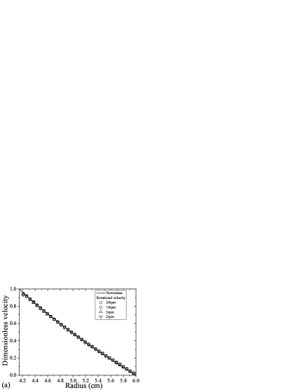
In Fig. 2a we observe that the velocity profiles in the gap of a Couette geometry are, as expected, in perfect agreement with the theory for a Newtonian flow (Eq. 6). This first observation can be seen as a validation of the measurement technique.
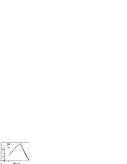
In the vane-in-cup geometry (Fig. 2b), we first note that the -averaged dimensionless azimuthal velocity profiles measured for several rotational velocities are superposed, as expected from the linear behavior of the material. We also remark that the material between the blades rotates as a rigid body only up to cm, indicating that the shear flow enters deeply the region between the blades (the vane radius is 4.02 cm). The whole limit between the sheared and the unsheared material in the () plane will be determined in Sec. IIIA3 (Fig. 4b). We finally observe that the theoretical velocity profile for a Newtonian fluid in a Couette geometry of radius equal to that of the vane lies above the data, as expected from the literature. This is also consistent with the observation that the shear flow enters the region between the vane blades.
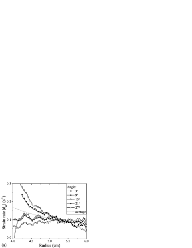
In order to test the Couette analogy, we have chosen to plot the -averaged strain rate vs. the radius in Fig. 3. This allows us to distinguish more clearly the difference between the experimental and theoretical flow properties than would the velocity profiles, because the velocity profile always tends to the same limit () at the outer cylinder whereas the strain rate profile does not. Note that velocity measurements could not be performed close to the blades, which explains why strain rate data are missing from 4 to 4.2 cm.
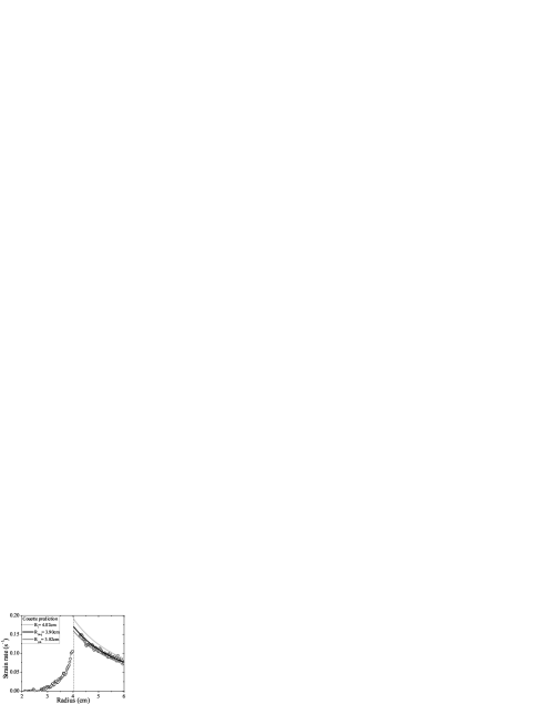
In Fig. 3, we first note that is zero up to cm, which corresponds to the limit of the rigid motion of the material; then increases when tends towards as the material is more and more sheared between the blades. In the gap of the geometry, decreases when increases. As expected, the theoretical strain rate profile for a Newtonian material in a Couette geometry of radius equal to that of the vane falls well above the data at any radius (this was less obvious on the velocity profiles). We then observe that the data are well fitted to the theoretical strain rate profile (Eq. 14) for a Newtonian material flowing in an equivalent Couette geometry of inner cylinder radius cm ( cm was obtained from a fit of the velocity profile to Eq. 13). This confirms that the -averaged strain rate decreases as the inverse squared radius in the gap, in agreement with the Couette analogy.
From Eq. 12, we find (let us recall that we do not need to consider end effects here because we determine the shear rate within the gap, and hence only the contribution to the torque from the material sheared in the gap). This value can now be compared to data from the literature. For a six-bladed vane tool in an infinite medium, the Atkinson and Sherwood (1992) theory would imply a theoretical , which is 8% lower than what we measure, and corresponds to a theoretical “equivalent radius” cm when the vane is embedded in a cup of radius cm. Figs. 2b and 3 show that the flow characteristics predicted with this value of the equivalent radius can be distinguished from our experimental data and fall slightly below the data (a discrepancy could be expected as is not small in our experiment).
| Study | Lower | |||||
|---|---|---|---|---|---|---|
| bound | ||||||
| Atkinson and Sherwood (1992) (th.) | 4 | 0 | 0 | 0.75 | – | |
| Zhang et al. (1998) (num.) | 4 | 2 | – | – | 0.65 | 0.56 |
| Martínez-Padilla and Quemada (2007) (exp.) | 4 | 1.825 | 0.6 | 0.045 | 0.67 | 0.52 |
| Zhu et al. (2010) (num.) | 4 | 1.14 | 0.14 | 0.1 | 0.73 | 0.26 |
| Barnes and Carnali (1990) (num.) | 4 | 1.12 | 0.35 | 0.12 | 0.61 | 0.24 |
| Atkinson and Sherwood (1992) (th.) | 6 | 0 | 0 | 0.83 | – | |
| Baravian et al. (2002) (exp.) | 6 | 2.55 | – | – | 0.7 | 0.7 |
| Zhang et al. (1998) (num.) | 6 | 2 | – | – | 0.74 | 0.63 |
| Present study (exp.) | 6 | 1.49 | 0.27 | 0.15 | 0.90 | 0.57 |
We have gathered experimental and numerical data from the literature where the cup to vane radius ratio is not large in Tab. 1; only data corrected for (or free from) end effects are shown. First, it should be noted that all torque data obey the theoretical inequalities computed using variational approaches in Sec. IIIA1. However, no clear trends emerge from the comparison of the data. The relative impact of the various geometrical parameters that may affect the flow field, namely the cup to vane radius ratio , the shaft radius to vane radius ratio , and the blade thickness to vane radius ratio , cannot be determined at this stage. For example, in very similar geometries, Zhu et al. (2010) find a torque ratio close to that of Atkinson and Sherwood (1992) whereas Barnes and Carnali (1990) find a much lower torque ratio. The only noticeable difference between these two studies (apart from the numerical method) is that is higher in Barnes and Carnali (1990), but our data, with a rather large value of , show different features. We actually note that our study is the only one to report a torque ratio higher than in an infinite medium; all other data report torque ratios up to 19% lower than expected in an infinite medium. In the general case of a finite vane-in-cup geometry, it thus seems that numerical investigations are still needed, and that, at this stage, a calibration has to be performed to get the geometry factors. We also expect that the bounds obtained using variational approaches in Sec. IIIA1 can be improved.
3 dependent profiles
To better characterize the flow field, we now study the dependence of the velocity profiles on the angular position . We have performed experiments in which we measure one azimuthal velocity profile per second while the vane tool is rotated at 1 rpm, yielding 10 profiles between two adjacent blades.
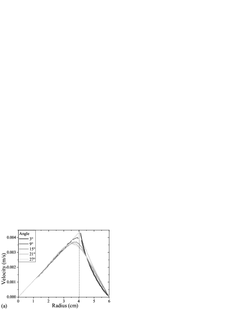
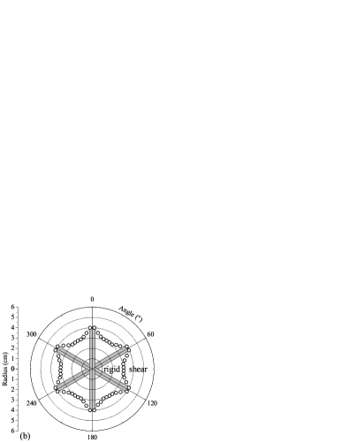
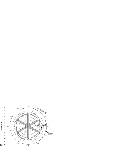
In Fig. 4a, we plot the velocity profiles measured at different angles . We first observe that the velocity profile which starts near from a blade tip (corresponding to ˚by definition) is very different from the velocity profile in a Couette geometry of same radius: it starts with a much steeper slope, which means that the blades tip neighborhoods are regions of important shear as already observed by Barnes and Carnali (1990). We then observe that, as expected from the -averaged velocity profiles, the shear flow enters more and more deeply the region between the blades as tends towards ˚(corresponding to midway between two adjacent blades); at this angular position, the rigid rotation stops at cm. From all the velocity profiles, we finally extract a 2D map of the limit between rigid rotation and shear, which is depicted in Fig. 4b. This provides an idea of the deviation from cylindrical symmetry, and will be compared in the following to the case of yield stress fluids. Note that eddies are likely to be present in the “rigid” region [Moffatt (1964); Atkinson and Sherwood (1992)]; however, we did not observe any signature of their existence: they can thus be considered as second-order phenomena.
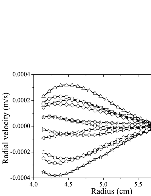
As explained in Sec. II, from the measurement and from the material incompressibility, we are able to reconstruct the radial velocity profile (see Fig. 5). This also allows us to compute the strain rate components and , which are plotted in Fig. 6. Of course, due to the limited number of profiles between two adjacent blades, this method provides only a rough estimate of these quantities. In addition to their interest for future comparison with models and simulations, these data allow us to evaluate the contribution of the extensional flow to dissipation; here, in a Newtonian medium, the local power density is given by: .
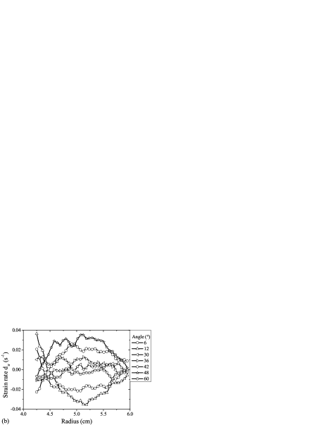
In Fig. 5, we first observe that for ˚and ˚; there is thus no extensional flow in these regions of space, as seen in Fig. 6. This is actually expected from the fore-aft symmetry of the flow around these angular positions. and its spatial variations (i.e. ) are maximal at ˚. Meanwhile, we observe that is maximal near the blades: at it is more than 4 times larger at ˚than at ˚. We then find that (and thus the shear stress ) decreases more rapidly from the blades (at ˚) than the scaling of the Couette geometry, whereas it does not vary much with midway between adjacent blades (it even seems to slightly increase with as already observed in simulations by Savarmand et al. (2007)). It is also worth nothing that at , in contrast with what is observed at , the shear stress value is of order two times lower at ˚than at ˚.
From the whole set of and measurements (Fig. 6), we finally find that in regions where is maximal, the contribution of the extensional flow to dissipation is of order 25%. Over the whole gap, we then evaluate its average contribution to dissipation to be rather important, of order 5 to 10%. This significant value may be a reason why the torque that has to be exerted to enforce flow is higher than that predicted by Atkinson and Sherwood (1992) in an infinite medium. The confinement effect induced by a close boundary at a radius likely increases the contribution of the extensional flow to dissipation as compared to the case of an infinite medium (although other effects may exist, as appears from the comparison of the data of Tab. 1).
B Yield stress fluid
In this section, we study the flows induced by the vane tool with a yield stress fluid (a concentrated emulsion). We focus on the behavior near the yielding transition, i.e. on low rotational velocities .
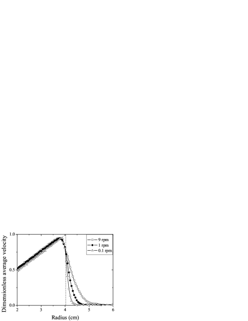
In Fig. 7, we plot the -averaged azimuthal velocity profiles measured at several values ranging from 0.1 to 9 rpm, corresponding to macroscopic shear rates varying between 0.02 and 2 s-1. We first observe that flow is localized: the material is sheared only up to a radius . is found to increase as increases. This is a classical feature of flows of yield stress fluids in heterogeneous stress fields. It has been observed in Couette geometries [Coussot (2005); Ovarlez et al. (2008)], where it is attributed to the decrease of the shear stress , which passes below at some at low . In this case, when tends to 0, tends to and the torque at the inner cylinder tends to . In the vane-in-cup geometry, the same argument holds qualitatively thanks to Eq. 8. It implies that the flow has to stop inside the gap at low . However, in contrast with the case of the Couette geometry, as the whole stress field a priori depends on , this -averaged equation does not provide the position of the limit between the sheared and the unsheared material (which will determined at the end of this section).
We then observe that, although this effect is less pronounced than with a Newtonian material, the shear flow still enters the region between the blades, even at the lowest studied . Close examination of the profiles shows that the material trapped between the blades rotates as a rigid body only up to cm at rpm, cm at rpm, and cm at rpm. We recall that cm with a Newtonian fluid in the same geometry.
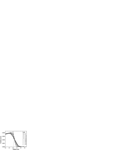
As in Sec. IIIA3, to better characterize the flow field, we have performed experiments in which we have measured 10 azimuthal profiles between two adjacent blades at 0.1 rpm. In Fig. 8, as for a Newtonian fluid, we observe that there is a strong -dependence of the velocity profiles. The velocity profile that starts near from a blade tip (at ˚) has a much steeper slope than the profile measured midway between adjacent blades (at ˚); again, this shows that the blade tip neighborhoods are regions of high shear. Meanwhile the flow stops at a radius which is larger at ˚(4.5 cm) than at ˚(4.3 cm). Note also that there may be slight fore-aft asymmetry, as sometimes observed with yield stress fluids flows [Dollet and Graner (2007); Putz et al. (2008)], but we did not study this point further. From these velocity profiles, we have reconstructed a 2D map of the flow field (Fig. 9), indicating both the boundary between the region of rigid body rotation (between the blades) and the sheared region, and the boundary between the sheared region and the outer region of fluid at rest (i.e. the position where the yield criterion is satisfied).
Flow is found to occur in a layer of complex shape which is far from being cylindrical even at this very low velocity. These observations are in contradiction with the usually accepted picture for yield stress fluid flows at low rates [Barnes and Nguyen (2001)], namely that the material contained in the virtual cylinder delimited by the blades rotates as a rigid body, and that it flows uniformly in a thin cylindrical layer near the blades. Our results contrast in particular with previous numerical works which showed that the yield surface is cylindrical at low rates for Bingham fluids, Casson fluids, and Herschel-Bulkley materials with [Keentok et al. (1985); Yan and James (1997); Savarmand et al. (2007)]. With apparently similar conditions to those in some of the Yan and James (1997) simulations, we find an important departure from cylindrical symmetry. This means that further investigation on the exact conditions under which this symmetry can be recovered is still needed. Possible difference between our work and that of Yan and James (1997) is that the blade thickness is zero in this last study.
It is particularly striking and counterintuitive that is largest at the angular position (˚) where shear at is smallest (similar observation was made by Potanin (2010)). As in Sec. IIIA3, this points out the importance of the extensional flow in this geometry, with -dependent normal stress differences which have to be taken into account in the yield criterion, and which thus impact the yield surface. It thus seems that the link between the yield stress and the torque measured at yield with a vane-in-cup geometry is still an open question, although the classical formula probably provides a sufficiently accurate determination of in practice.
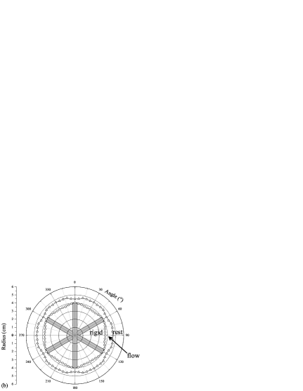
The same 2D map as above is plotted for rpm in Fig. 9; the same phenomena are observed, with enhanced departure from cylindrical symmetry, consistent with the observation that decreases when increases. This result was also unexpected, as simulations find uniform flows for shear-thinning material of index [Barnes and Carnali (1990); Savarmand et al. (2007)]; we would have expected the same phenomenology in a Herschel-Bulkley material of index (and thus to tend to when increasing ). This observation also shows that a Couette analogy can hardly be defined for studying the flow properties of such materials in a vane-in-cup geometry because the equivalent Couette geometry radius would probably depend also on (as recently shown by Zhu et al. (2010)).
Let us finally note that this departure from cylindrical symmetry has important impact on the migration of particles in a yield stress fluid (see below).
C Concentrated suspension
In this section, we investigate the behavior of a concentrated suspension of noncolloidal particles in a yield stress fluid (at a 40% volume fraction).
A detailed study of their velocity profiles would a priori present here limited interest: such materials present the same nonlinear macroscopic behavior as the interstitial yield stress fluid, and their rheological properties (yield stress, consistency) depend moderately on the particle volume fraction [Mahaut et al. (2008a); Chateau et al. (2008)].
On the other hand, noncolloidal particles in suspensions are known to be prone to shear-induced migration, which leads to volume fraction heterogeneities. This phenomenon is well documented in the case of suspensions in Newtonian fluids [Leighton and Acrivos (1987b); Abbott et al. (1991); Phillips et al. (1992); Corbett et al. (1995); Shapley et al. (2004); Ovarlez et al. (2006)] but is still badly known in yield stress fluids (some studies exist however in viscoelastic fluids [Tehrani (1996); Huang and Joseph (2000); Lormand and Phillips (2004)]). In the model of Leighton and Acrivos (1987b) and Phillips et al. (1992), migration is related to shear-induced diffusion of the particles [Leighton and Acrivos (1987a); Acrivos (1995)]. In a wide gap Couette geometry, the shear stress heterogeneity is important (Eq. 4); the shear rate gradients then generate a particle flux towards the low shear zones, which is counterbalanced by a particle flux due to viscosity gradients. A steady state, which results from competition between both fluxes, may then be reached, and is characterized by an excess of particles in the low shear zones of the flow geometry (near the outer cylinder in a wide-gap Couette geometry [Phillips et al. (1992); Corbett et al. (1995); Ovarlez et al. (2006)]). Note that there are other models [Nott and Brady (1994); Mills and Snabre (1995); Morris and Boulay (1999); Lhuillier (2009)] in which particle fluxes counterbalance the gradients in the particle normal stresses, and which can be used directly for non-Newtonian media.
As the development of migration depends on the spatial variations of shear, one may wonder how the azimuthal heterogeneities of shear introduced by the vane tool affect migration; a related question is that of the relevance of the Couette analogy for this phenomenon. In the following, we thus focus on the particle volume fraction distribution evolution when the material is sheared.
Behavior at high shear rate
We first study the behavior at high shear rate, in the absence of shear localization. We shear the suspension in both the standard Couette geometry and the vane-in-cup geometry at a rotational velocity rpm. In this first set of experiments, we only study the steady-state of migration. At rpm, this steady-state is reached in less than 30 min (which corresponds to a macroscopic strain of order 50000, consistently with strainscale evaluations from data of the literature [Ovarlez et al. (2006)]). In Fig. 10 we plot the steady state volume fraction profiles observed after shearing the suspension at rpm during 1h.
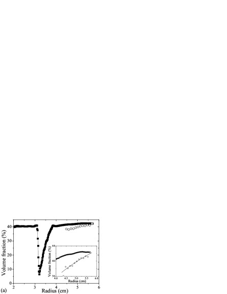

As expected, we first observe that the material is strongly heterogeneous in the Couette geometry: the volume fraction varies between 37% near the inner cylinder and 43% near the outer cylinder (note that the NMR technique we use do not allow quantitative measurements near the walls). This heterogeneity is quantitatively similar to that observed in Couette flows of Newtonian suspensions at a same 40% particle volume fraction [Corbett et al. (1995)]; the profiles are actually well fitted to the Phillips et al. (1992) model (see Eq. 16 of Ovarlez et al. (2006)) with a dimensionless diffusion constant which is close to that found by Corbett et al. (1995) (), although this model is not expected to hold in non-Newtonian suspensions.
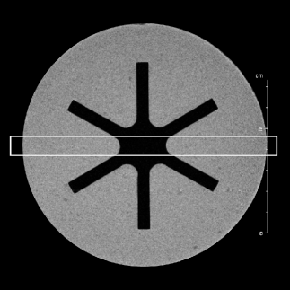
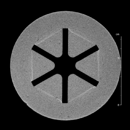
In the vane-in-cup geometry, the volume fraction profile shows very different features; note that the profile is measured in a 1 cm thick (in the azimuthal direction) slice situated exactly between two adjacent blades (see Fig. 11). In Fig. 10, we first observe that there is a strong particle depletion in a wide zone between the blades. A homogeneous volume fraction of 40% is observed for radii inferior to 3.1 cm. At a radius cm, there is a strong drop in the volume fraction down to 5% within 1 mm (corresponding to 4 particle diameters). Close inspection of the velocity profile Fig. 10 shows that this radius corresponds to the transition between rigid motion and shear between the blades. The volume fraction then increases basically linearly with the radius up to a 40.5% volume fraction at a radius cm which is close to the vane radius. The volume fraction then increases only slightly (between 40.5% and 42.5%) in the gap of the geometry: the heterogeneity is here much less important than in a standard Couette geometry.
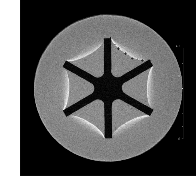
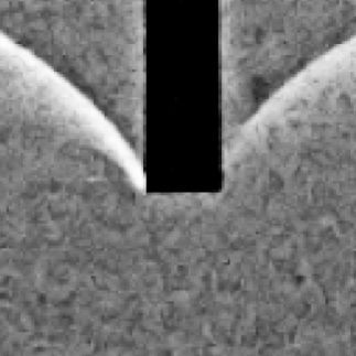
To get further insight into the new strong depletion phenomenon we have evidenced, we have performed 2D magnetic resonance images of the material. Such images provide a qualitative view of the spatial variations of the particle volume fraction as only the liquid phase is imaged. Images are coded in grey scales; a brighter zone contains less particles. In Fig. 11b, we first see an image of the homogeneous material. Before any shear, as expected, the light intensity is homogeneous in the sample (intensity variations correspond to noise). After a 1h shear at rpm, we observe very bright and thin curves on the image: they correspond to zones where the volume fraction suddenly drops down to a value close to zero. These curves are not circles. More precisely, between two adjacent blades, a depleted zone goes from the edge of one blade (at ˚, cm) to the edge of another blade (at ˚, cm), and describes a concave curve whose minimum is cm at ˚. Note that as the volume fraction profile is averaged over a slice which is 1 cm thick in the azimuthal direction (see Fig. 11b), the fact that we measure a minimum of 5% at cm in the slice probably means that the volume fraction minimum is actually equal to zero in the depletion zone.
(a)
(b) (c)
As pointed out above, this curve also likely marks the transition between the unsheared material (which rotates as a rigid body) and the sheared material. Note in particular the similarity with Fig. 4b, the data of which are reported in Fig. 11a for illustration. A first interpretation of the phenomenon would then simply be that migration is caused by shear and naturally stops at this transition zone. Indeed, as shear is maximum near the blades, particles tends to migrate out of this zone; moreover, there is no source of particle flux from the unsheared zone between the blades to balance the migration towards the outer cylinder. However, this does not explain why the volume fraction drops down to zero: heterogeneities observed at steady-state in the literature are usually moderate and do not lead to zones free of particles. A better understanding of the phenomenon can be gained by zooming on the previous image (Fig.11c). We now see that while the depletion phenomenon seems symmetric around both sides of the blades at a macroscopic scale, it is clearly asymmetric at a local scale near the blades and depends on the direction of rotation: depletion is more pronounced at the back of the blade (note that the vane tool rotates counterclockwise). This would mean that the noncolloidal particle trajectories are asymmetric around the blade: a particle that is found at a radius cm just before the blade is necessarily found at a radius slightly higher than 4.02 cm after the blade as there are no particles at cm. This feature is reminiscent of the fore-aft asymmetry that is observed in the bulk of noncolloidal suspensions [Parsi and Gadala-Maria (1987)] and that leads to their non-Newtonian properties [Brady and Morris (1997)]. It thus seems that, in addition to the shear-induced migration mechanism intrinsic to suspensions, the vane tool induces a specific migration mechanism which has its origin in the direct interactions between the particles and the blades; this effects leads to the full depletion that is observed at the transition between the sheared and the unsheared material. Such direct effect of a flow geometry on migration has also been observed in microchannel flows of colloidal suspensions [Wyss et al. (2006)], and also led to full particle depletion. See also Jossic and Magnin (2004). The kinetics of the phenomenon will be briefly discussed below.
The rest of the volume fraction profile results from a complex interplay between shear-induced migration and the fore-aft asymmetry around the blades; this leads to the rapid increase of the volume fraction between 3.1 cm and 4.02 cm. After 4.02 cm the flow lines do not meet the blade edges, and the phenomenon evidenced above should have basically no effect on the heterogeneity that develops in the gap of the geometry. On the other hand, the mean volume fraction should be slightly higher due to mass conservation; it is indeed observed to be equal to around 42%. Nevertheless, as the mean radial shear rate heterogeneity is basically similar to that observed in a standard Couette geometry (see previous sections), we would a priori expect the heterogeneity to be somehow similar. However, we observe that the volume fraction profile is only slightly heterogeneous: there is less than 5% variation of the volume fraction in the gap, to be compared to the 15% variation observed in the Couette geometry. Clearly, this means that the Couette analogy is irrelevant as regards this phenomenon, and that the details of shear matter. Here, the extensional flow that adds to shear may be at the origin of this diminution of migration. A more detailed analysis is out of the scope of this paper.
Behavior at low shear rate
Let us now study the behavior at low shear rate. Low shear rates are typically imposed with the aim of measuring the yield stress of such materials. Starting from a homogeneous suspension at rest, we apply a rotational velocity rpm (without any preshear), and we measure the evolution of the particle volume fraction in time. The corresponding volume fraction profiles are depicted in Fig. 12.
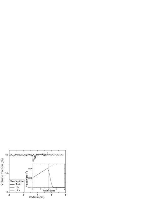
In Fig. 12, we observe that, although shear is much less important than in the previous experiments, particle depletion also appears between the blades. Comparison of the velocity profile and the volume fraction profile shows that depletion also appears between the blades at the transition zone between the sheared and the unsheared materials. This phenomenon appears with a very fast kinetics: the lower volume fraction value in the measurement zone is 36% after only a 5 minute shear (corresponding to a macroscopic strain of order 50). Afterwards, it continues evolving slowly: the minimum observed volume fraction is of order 33% after a 1h shear and of order 32% after a 14h shear (corresponding to a 10000 macroscopic strain). Note that the radial position of the minimum value of the volume fraction slightly decreases in time; it likely corresponds to progressive erosion of the material between the blades (we did not measure the velocity profiles to check this hypothesis).
We also note that migration is negligible in the rest of the sheared material as expected from the theory of migration briefly described above (a larger strain would be needed to observe significant migration). Nevertheless, we note some particle accumulation (with a volume fraction value of 43%) at =4.7 cm after a very long time. This corresponds to the yield surface as flow is localized at low velocity (see velocity profile Fig. 12). Migration profiles usually result from an equilibrium between various sources of fluxes. On the other hand, the unsheared material does not produce any particle flux while it receives particles from the sheared region. This particle accumulation is thus the signature that the migration phenomenon is indeed active, although not observable on the profile measured in the sheared zone. It is probable that this accumulation process would stop only (after a very long time) when there are no more particles in the sheared region.
(a) (b)
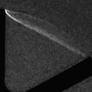
As above, 2D magnetic resonance images of the material provide an
insight in the phenomenon. In Fig. 13, we
observe again that particle depletion is enhanced at the rear of
the blades; this confirms that this phenomenon is likely due to
direct interactions between the blades and the particles, leading
to the asymmetry of the particles trajectory around the blades.
This a priori occurs with any particle whose trajectory
is close to the blades, explaining why particle depletion appears
so rapidly. There is probably no way to avoid it. Note that the
images are here much brighter very close to the blades than midway
between two adjacent blades; this would mean that the particle
volume fraction is probably
close to near the blades, although we observe volume fraction of order 32% between two blades.
Consequences: slip with a vane tool
We finally present some consequences of this phenomenon. From the above observations, our conclusion is that depletion sets up quickly and is probably unavoidable. Then two situations have to be distinguished. If linear viscoelastic properties of a suspension of large particles are measured at rest on the homogeneous material in its solid regime, without any preshear, then these measurements pose no other problem than that of the relevant Couette analogy to be used (see Sec. IIIA). If a yield stress measurement is performed at low imposed rotational velocity, starting from the homogeneous material at rest, then this measurement is likely valid as long as only the peak value or the plateau value at low strain (of order 1) is recorded. On the other hand, any subsequent analysis of the material behavior will a priori be misleading: irreversible changes have occurred and the material cannot be studied anymore. More generally, any measurement performed after a preshear will be incorrect and any flow curve measurement will lead to wrong evaluation of the material properties. In these last cases, the consequence of the new particle depletion phenomenon we have evidenced is a kind of wall slip near the blades, whereas there are no walls. Here the “slip layer” is made of the (pure) interstitial yield stress fluid in a zone close to the blades, as would be observed near a smooth inner cylinder. This contrasts with the common belief that the vane tool prevents slippage.
In order to illustrate this feature, we present some results of Mahaut et al. (2008a): Mahaut et al. performed classical upward/downward shear rate sweeps with a six-bladed vane-in-cup geometry ( cm, cm, 4.5 cm, blade thickness=0.8 mm) in a pure concentrated emulsion, and in the same emulsion filled with 20% of 140 m PS beads. In these experiments, constant macroscopic shear rates steps increasing from 0.01 to 10 s-1 and then decreasing from 10 to 0.01 s-1 were applied during 30s, and the stationary shear stress was measured for each shear rate value. The results are shown in Fig. 14.
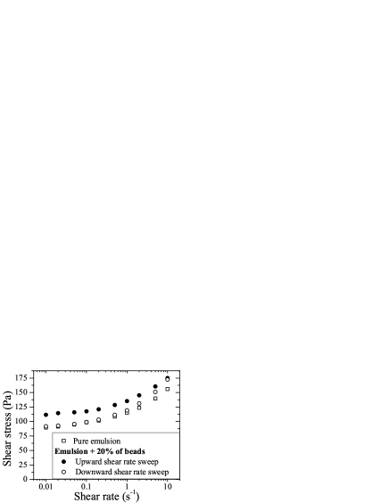
While the same curve is observed for the upward/downward shear rate sweeps in the case of the pure emulsion (as expected for a simple non-thixotropic yield stress fluid), the shear stress during the upward shear rate sweep differs from the shear stress during the downward shear rate sweep in the case of the suspension. Moreover, any measurement performed on the suspension after this experiment gives a static yield stress equal to the dynamic yield stress observed during the downward sweep. This means that there has been some irreversible change. This irreversible change is actually the particle depletion near the blades we have observed in this paper. As the flow of the suspension is localized near the inner tool at low shear rate, it means that after the first upward sweep that has induced the particle depletion, during the downward shear rate sweep only the pure emulsion created by migration near the blades remains in the sheared layer at sufficiently low rotational velocity. This explains why the same apparent value of the yield stress is found in the suspension during the downward sweep as in the pure emulsion with this experiment. On the other hand, the yield stress at the beginning of the very first upward sweep is that of the suspension as migration has not occurred yet.
The conclusion is that the vane tool is probably not suitable to the study of flows of suspensions of large particles.
IV Conclusion
As a conclusion, let us summarize our main findings:
-
•
In the case of Newtonian fluid flows, our measurements support the Couette equivalence approach: the -averaged strain rate component decreases as the inverse squared radius in the gap. Interestingly, the velocity profiles allow determining the Couette equivalent radius without end-effect correction and independently of the viscosity of the material. The torque exerted by the vane in our display is found to be higher (by 8%) than the theoretical prediction of Atkinson and Sherwood (1992) for a vane embedded in an infinite medium, and is thus much closer to the torque exerted by a Couette geometry of same radius as the vane than expected from the literature. A key observation may be that there is a significant flow between the blades which adds an important extensional component to shear, thus increasing dissipation. From a short review of the literature, it clearly appears that numerical investigations are still needed in the case of finite geometries. Variational approaches are also promising, although they do not yet provide tight bounds.
-
•
In the case of yield stress fluid flows, we find that the thin layer of material which flows around the vane tool at low velocity is not cylindrical, in contrast with what is usually supposed in the literature from simulation results. Consequently, a non negligible extensional component of shear has probably to be taken into account in the analysis. At this stage, there are too few experimental and simulation data to understand the origin of this discrepancy. It thus seems that progress still has to be made, in particular through simulations, which allow a wide range of parameters to be studied. This may help understanding how the torque is linked to the yield stress of a material at low velocity, depending in particular on the geometry.
-
•
An important and surprising result is the observation of particle depletion near the blades when the yield stress fluid contains noncolloidal particles. This phenomenon is thus likely to occur when studying polydisperse pastes like coal slurries, mortars and fresh concrete. It has to be noted that the phenomenon is very rapid, irreversible, and thus probably unavoidable when studying flows of suspensions of large particles. It results in the creation of a pure interstitial yield stress fluid layer and thus in a kind of wall slip near the blades. It contrasts with the classical assumption that is made in the field of concentrated suspension rheology where the vane tool is mainly used to avoid this phenomenon.
Consequently, we would say that, in the case of pasty materials with large particles, if accurate measurements are needed, the vane tool may finally be suitable only for the study of the solid (elastic) properties of materials and for the static yield stress measurements; as the yield stress measurement may induce irreversible particle depletion near the blades, any new measurement then requires a new sample preparation. Furthermore, the vane can be used as a very accurate tool without any hypothesis nor any calibration to measure the relative increase of the elastic modulus of materials as a function of their composition [Alderman et al. (1991); Mahaut et al. (2008a)]. In order to study accurately the flows of pasty materials with large particles, our results suggest that a coaxial cylinders geometry with properly roughened surfaces is preferable when possible. If the use of a vane tool cannot be avoided, one should keep in mind our observations in order to carefully interpret any result.
References
- Abbott et al. (1991) Abbott, J. R., N. Tetlow, A. L. Graham, S. A. Altobelli, E. Fukushima, L. A. Mondy, and T. S. Stephens, “Experimental observations of particle migration in concentrated suspensions: Couette flow,” J. Rheol. 35, 773-795 (1991).
- Acrivos (1995) Acrivos, A., “BINGHAM AWARD LECTURE–1994 Shear-induced particle diffusion in concentrated suspensions of noncolloidal particles,” J. Rheol. 39, 813-826 (1995).
- Aït-Kadi et al. (2002) Aït-Kadi, A., P. Marchal, L. Choplin, A.-S. Chrissemant, and M.Bousmina, “Quantitative Analysis of Mixer-Type Rheometers using the Couette Analogy,” The Canadian Journal of Chemical Engineering 80, 1166-1174 (2002).
- Alderman et al. (1991) Alderman, N. J., G. H. Meeten, and J. D. Sherwood, “Vane rheometry of bentonite gels,” J. Non-Newtonian Fluid Mech. 39, 291-310 (1991).
- Atkinson and Sherwood (1992) Atkinson, C., and J. D. Sherwood, “The Torque on a Rotating N-Bladed Vane in a Newtonian Fluid or Linear Elastic Medium,” Proceedings of the Royal Society of London Series a-Mathematical Physical and Engineering Sciences 438, 183-196 (1992).
- Baravian et al. (2002) Baravian, C., A. Lalante, and A. Parker, “Vane rheometry with a large, finite gap,” Applied Rheology 12, 81-87 (2002).
- Barnes and Carnali (1990) Barnes, H. A., and J. O. Carnali, “The Vane-in-Cup as a Novel Rheometer Geometry for Shear Thinning and Thixotropic Materials,” J. Rheol. 34, 841-866 (1990).
- Barnes and Nguyen (2001) Barnes, H. A., and Q. D. Nguyen, “Rotating vane rheometry - a review,” J. Non-Newtonian Fluid Mech. 98, 1-14 (2001).
- Brady and Morris (1997) Brady, J. F., and J. F. Morris, “Microstructure of strongly sheared suspensions and its impact on rheology and diffusion,” J. Fluid Mech. 348, 103-139 (1997).
- Bousmina et al. (1999) Bousmina, M., A. Aït-Kadi, and J. B. Faisant, “Determination of shear rate and viscosity from batch mixer data,” J. Rheol. 43, 415-433 (1999).
- Callaghan (1991) Callaghan, P. T., Principles of Nuclear Magnetic Resonance Spectroscopy (Clarendon, Oxford, 1991).
- Chateau et al. (2008) Chateau, X., G. Ovarlez, and K. Luu Trung, “Homogenization approach to the behavior of suspensions of noncolloidal particles in yield stress fluids,” J. Rheol. 52, 489-506 (2008).
- Corbett et al. (1995) Corbett, A. M., R. J. Phillips, R. J. Kauten, and K. L. McCarthy, “Magnetic resonance imaging of concentration and velocity profiles of pure fluids and solid suspensions in rotating geometries,” J. Rheol. 39, 907-924 (1995).
- Coussot (2005) Coussot, P., Rheometry of Pastes, Suspensions and Granular Materials (John Wiley & Sons, New York, 2005).
- Dollet and Graner (2007) Dollet, B., and F. Graner, “Two-dimensional flow of foam around a circular obstacle: local measurements of elasticity, plasticity and flow,” J. Fluid Mech. 585, 181-211 (2007).
- Dzuy and Boger (1983) Dzuy, N. Q., and D. V. Boger, “Yield stress measurement for concentrated suspensions,” J. Rheol. 27, 321 (1983).
- Estellé et al. (2008) Estellé, P., C. Lanos, A. Perrot, and S. Amziane, “Processing the vane shear flow data from Couette analogy,” Applied Rheology 18, 34037-34481 (2008).
- Hanlon et al. (1998) Hanlon, A. D., S. J. Gibbs, L. D. Hall, D. E. Haycock, W. J. Frith, S. Ablett, and C. Marriott, “A concentric cylinder Couette flow system for use in magnetic resonance imaging experiments,” Measurement Science and Technology 9, 631-637 (1998).
- Huang and Joseph (2000) Huang, P. Y., and D. D. Joseph, “Effects of shear thinning on migration of neutrally buoyant particles in pressure driven flow of Newtonian and viscoelastic fluids,” J. Non-Newtonian Fluid Mech. 90, 159-185 (2000).
- Jau and Yang (2010) Jau, W.-C., and C.-T. Yang, “Development of a modified concrete rheometer to measure the rheological behavior of fresh concrete,” Cement and Concrete Composites (2010), In Press doi:10.1016/j.cemconcomp.2010.01.001
- Jossic and Magnin (2004) Jossic, L. and A. Magnin, “Structuring under flow of suspensions in a gel,” AIChE Journal 50, 2691-2696 (2004).
- Keentok (1982) Keentok, M., “The measurement of the yield stress of liquids,” Rheologica Acta 21, 325-332 (1982).
- Keentok et al. (1985) Keentok, M., J. F. Milthorpe, and E. O’Donovan, “On the shearing zone around rotating vanes in plastic liquids: theory and experiment,” J. Non-Newtonian Fluid Mech. 17, 23-35 (1985).
- Koehler et al. (2006) Koehler E. P., D. W. Fowler, C. F. Ferraris, and S. A. Amziane, “New, portable rheometer for fresh self-consolidating concrete,” ACI Mater J 233, 97-116 (2006).
- Leighton and Acrivos (1987a) Leighton, D., and A. Acrivos, “Measurement of shear-induced self-diffusion in concentrated suspensions of spheres,” J. Fluid Mech. 177, 109-131 (1987a).
- Leighton and Acrivos (1987b) Leighton, D., and A. Acrivos, “The shear-induced migration of particles in concentrated suspensions,” J. Fluid Mech. 181, 415-439 (1987b).
- Lhuillier (2009) Lhuillier, D., “Migration of rigid particles in non-Brownian viscous suspensions,” Phys. Fluids 21, 023302 (2009).
- Lormand and Phillips (2004) Lormand, B. M., and R. J. Phillips, “Sphere migration in oscillatory Couette flow of a viscoelastic fluid,” J. Rheol. 48, 551-570 (2004).
- Mahaut et al. (2008a) Mahaut, F., X. Chateau, P. Coussot, and G. Ovarlez, “Yield stress and elastic modulus of suspensions of noncolloidal particles in yield stress fluids,” J. Rheol. 52, 287-313 (2008).
- Mahaut et al. (2008b) Mahaut, F., S. Mokéddem, X. Chateau, N. Roussel, and G. Ovarlez, “Effect of coarse particle volume fraction on the yield stress and thixotropy of cementitious materials,” Cem. Concr. Res. 38, 1276-1285 (2008).
- Martínez-Padilla and Rivera-Vargas (2006) Martínez-Padilla, L. P., and C. Rivera-Vargas, “Flow behavior of Mexican sauces using a vane-in-a-large cup rheometer,” Journal of Food Engineering 72, 189-196 (2006).
- Martínez-Padilla and Quemada (2007) Martínez-Padilla, L. P., and D. Quemada, “Baffled cup and end-effects of a vane-in-a-large cup rheometer for Newtonian fluids,” Journal of Food Engineering 80, 24-32 (2007).
- Mills and Snabre (1995) Mills, P., and P. Snabre, “Rheology and Structure of Concentrated Suspensions of Hard Spheres. Shear Induced Particle Migration,” J. Phys. II France 5, 1597-1608 (1995).
- Moffatt (1964) Moffatt, H. K., “Viscous and resistive eddies near a sharp corner,” J. Fluid Mech. 18, 1-18 (1964).
- Morris and Boulay (1999) Morris, J. F., and F. Boulay, “Curvilinear flows of noncolloidal suspensions: The role of normal stresses,” J. Rheol. 43, 1213-1237 (1999).
- Nguyen and Boger (1992) Nguyen, Q. D., and D. V. Boger, “Measuring the flow properties of yield stress fluids,” Annu. Rev. Fluid Mech. 24, 47-88 (1992)
- Nott and Brady (1994) Nott, P., and J. F. Brady, “Pressure-driven flow of suspensions: Simulation and theory,” J. Fluid Mech. 275, 157-199 (1994).
- Ovarlez et al. (2006) Ovarlez, G., F. Bertrand, and S. Rodts, “Local determination of the constitutive law of a dense suspension of noncolloidal particles through magnetic resonance imaging,” J. Rheol. 50, 259-292 (2006).
- Ovarlez et al. (2008) Ovarlez, G., S. Rodts, A. Ragouilliaux, P. Coussot, J. Goyon, and A. Colin, “Wide-gap Couette flows of dense emulsions: Local concentration measurements, and comparison between macroscopic and local constitutive law measurements through magnetic resonance imaging,” Phys. Rev. E 78, 036307 (2008).
- Ovarlez et al. (2010) Ovarlez, G., Q. Barral, and P. Coussot, “Three-dimensional jamming and flows of soft glassy materials,” Nature Materials 9, 115-119 (2010).
- Parsi and Gadala-Maria (1987) Parsi, F., and F. Gadala-Maria, “Fore-and-aft asymmetry in a concentrated suspension of solid spheres,” J. Rheol. 31, 725-732 (1987).
- Phillips et al. (1992) Phillips, R. J., R. C. Armstrong, R. A. Brown, A. L. Graham, and J. R. Abbott, “A constitutive equation for concentrated suspensions that accounts for shear-induced particle migration,” Phys. Fluids 4, 30-40 (1992).
- Potanin (2010) Potanin, A., “3D simulations of the flow of thixotropic fluids, in large-gap Couette and vane-cup geometries,” J. Non-Newtonian Fluid Mech. 165, 299-312 (2010).
- Putz et al. (2008) Putz, A. M. V., T. I. Burghelea, I. A. Frigaard, and D. M. Martinez, “Settling of an isolated spherical particle in a yield stress shear thinning fluid,” Phys. Fluids 20, 033102 (2008).
- Raynaud et al. (2002) Raynaud, J. S., P. Moucheront, J. C. Baudez, F. Bertrand, J. P. Guilbaud, and P. Coussot, “Direct determination by NMR of the thixotropic and yielding behavior of suspensions,” J. Rheol. 46, 709-732 (2002).
- Richards (1988) Richards, A. F. (ed.), Vane Shear Strength Testing in Soils: Field and Laboratory Studies (ASTM, Philadelphia, 1988).
- Rodts et al. (2004) Rodts, S. , F. Bertrand, S. Jarny, P. Poullain, and P. Moucheront, “Développements récents dans l’application de l’IRM à la rhéologie et à la mécanique des fluides,” Comptes Rendus Chimie 7, 275-282 (2004).
- Saak et al. (2001) Saak, A. W., H. M. Jennings, and S. P. Shah, “The influence of wall slip on yield stress and viscoelastic measurements of cement paste,” Cem. Concr. Res. 31, 205-212 (2001).
- Salençon (2001) Salençon, J., Handbook of continuum mechanics. General concepts, thermoelasticity (Springer-Verlag, Berlin, Heildeberg, 2001).
- Savarmand et al. (2007) Savarmand, S., M. Heniche, V. Bechard, F. Bertrand, and P. J. Carreau, “Analysis of the vane rheometer using 3D finite element simulation,” J. Rheol 51, 161-177 (2007).
- Shapley et al. (2004) Shapley, N. C., R. A. Brown, and R. C. Armstrong, “Evaluation of particle migration models based on laser Doppler velocimetry measurements in concentrated suspensions,” J. Rheol. 48, 255-279 (2004).
- Sherwood and Meeten (1991) Sherwood, J. D., and G. H. Meeten, “The use of the vane to measure the shear modulus of linear elastic solids,” J. Non-Newtonian Fluid Mech. 41, 101-118 (1991).
- Stokes and Telford (2004) Stokes, J. R., and J. H. Telford, “Measuring the yield behaviour of structured fluids,” J. Non-Newtonian Fluid Mech. 124, 137-146 (2004).
- Tehrani (1996) Tehrani, M. A.,“An experimental study of particle migration in pipe flow of viscoelastic fluids,” J. Rheol. 40, 1057-1077 (1996).
- Wallevik (2008) Wallevik, J. E., “Minimizing end-effects in the coaxial cylinders viscometer: Viscoplastic flow inside the ConTec BML Viscometer 3 ,” J. Non-Newtonian Fluid Mech. 155, 116-123 (2008).
- Wyss et al. (2006) Wyss, H. M., D. L. Blair, J. F. Morris, H. A. Stone, and D. A. Weitz, “Mechanism for clogging of microchannels,” Phys. Rev. E 74, 061402 (2006).
- Yan and James (1997) Yan, J., and A. E. James, “The yield surface of viscoelastic and plastic fluids in a vane viscometer,” J. Non-Newtonian Fluid Mech. 70, 237-253 (1997).
- Zhu et al. (2010) Zhu, H., N. S. Martys, C. ferraris, and D. De Kee, “A numerical study of the flow of Bingham-like fluids in two-dimensional vane and cylinder rheometers using a smoothed particle hydrodynamics (SPH) based method,” J. Non-Newtonian Fluid Mech. 165, 362-375 (2010).
- Zhang et al. (1998) Zhang, X. D., D. W. Giles, V. H. Barocas, K. Yasunaga, and C. W. Macosko, “Measurement of foam modulus via a vane rheometer,” J. Rheol. 42, 871-888 (1998).