Hyperentangled mixed phased Dicke states: optical design and detection
Abstract
We present an experimental method to produce 4-qubit phased Dicke states, based on a source of 2-photon hyperentangled states. By introducing quantum noise in the multipartite system in a controlled way, we have tested the robustness of these states. To this purpose the entanglement of the resulting multipartite entangled mixed states has been verified by using a new kind of structural witness.
The generation and detection of multipartite entangled states is a remarkable challenge that needs to be accomplished in order to fully explore and exploit the genuine quantum features of quantum information and many-body physics. So far only a limited number of families of pure multipartite entangled states has been experimentally produced. In view of future applications, it is particularly important to test the robustness of the generated states in the presence of unavoidable noise coming from the environment. Here, we produce a new family of multipartite maximally entangled states, we experimentally introduce certain types of noise in a controlled way and test the robustness properties of the states.
The experimental generation of multipartite entangled states that we propose is based on hyperentangled photons Barbieri et al. (2005), which allows to produce symmetric and phased Dicke states. Dicke states have recently attracted much interest, and have been produced in experiments with photons Kiesel et al. (2007); Prevedel et al. (2009); Wieczorek et al. (2009). Phased Dicke states represent a more general family of entangled states with respect to the ordinary symmetric Dicke states: they are achieved by introducing phase changes starting from ordinary Dicke states.
In order to test the presence of multipartite entanglement we may adopt different kinds of entanglement witnesses. Their experimental implementations are presented, e.g., in Refs. Barbieri et al. (2003) for bipartite qubits, and Bourennane et al. (2004); Kiesel et al. (2007); Prevedel et al. (2009); Wieczorek et al. (2009) for pure symmetric multipartite states. In this work we implement a recently proposed new class of entanglement witnesses, so-called structural witnesses Krammer et al. (2009), and further extend such a class in order to achieve higher efficiency in entanglement detection. Moreover, we test the robustness of the phased Dicke states by introducing dephasing noise in a controlled fashion and provide a measurement of the lower bound on the robustness of entanglement. In this way we provide a new experimental tool to investigate the entanglement properties of multipartite mixed states.
An entanglement witness is defined as a Hermitian operator that detects the entanglement of a state if it has a negative expectation value for this state, while at the same time for all separable states Horodecki et al. (1996); Terhal (2000). For a composite system of particles, the structural witnesses Krammer et al. (2009) have the form
| (1) |
where is a real parameter (the wave-vector transfer in a scattering scenario), is the identity operator and
| (2) |
with
| (3) | |||||
Here is the binomial coefficient and the structure factor operators are defined as
| (4) |
where denote the -th and -th spins, their positions in a one-dimensional scenario, and are the spin operators with . In the following we normalize the distances with the labels of the qubits as . In the present work we focus on the case of 4-qubits phased Dicke states defined as Krammer et al. (2009):
| (5) | |||||
A suitable structural witness for the above phased Dicke state is given by the operator (1) with , and being the Pauli operators Krammer et al. (2009). This witness leads to .
A wider class of structural witness can be obtained by generalizing the operator given in (3) to linear superpositions of structure factor operators evaluated for different values of :
| (6) | |||||
Following the same argument as in Krammer et al. (2009), it can be shown that any operator of the form (6) combined as in (1) has non-negative expectation values for separable states and is therefore an entanglement witness. Using this more general construction for the present experiment we consider a witness operator with and :
| (7) |
The expectation value of the above witness for the phase Dicke state (5) is given by .
State generation - We will now describe the method to generate phased Dicke states and to implement controlled noise, and present the experimental results of entanglement detection. Let’s consider the following state . It is easy to show that the phased Dicke state can be obtained by applying a unitary transformation111An equivalent and more simple transformation is given by . We used the transformation given in (8) in order to compensate the optical delay introduced by the CX gates in the Sagnac loop of Fig. 1b). to the state :
| (8) |
where and stands for the Hadamard and the Pauli transformations on qubit , is the controlled-NOT gate and the controlled-Z. We realized the Dicke state by using 4-qubits encoded into polarization and path of two parametric photons [A and B in figure 1a)]. The and states are encoded into horizontal and vertical polarization or into right and left path. Explicitly, we used the following correspondence between physical states and logical qubits:
| (9) | ||||
| (10) | ||||
| (11) | ||||
| (12) |
According to these relations the state reads:
| (13) |
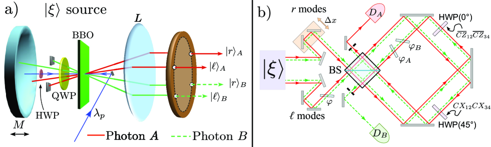
and may be obtained by suitably modifying the source used to realize polarization-momentum hyperentangled states Barbieri et al. (2005); Ceccarelli et al. (2009). In each “ket” of (13) the first (second) term refers to particle A (B). A vertically polarized UV laser beam impinges on a Type I -barium borate (BBO) nonlinear crystal in two opposite directions, back and forth, and determines the generation of the polarization entangled state corresponding to the superposition of the spontaneous parametric down conversion (SPDC) emission at degenerate wavelength [see Fig. 1a)]. A 4-hole mask selects four optical modes (two for each photon), namely , , and , within the emission cone of the crystal. The SPDC contribution, due to the pump beam incoming after reflection on mirror , corresponds to the term , whose weight is determined by a half waveplate intercepting the UV beam (see Vallone et al. (2007) for more details on the generation of the non-maximally polarization entangled state). The other SPDC contribution is determined by the first excitation of the pump beam: here the modes are intercepted by two beam stops and a quarter waveplate QWP transforms the SPDC emission into after reflection on mirror . The relative phase between the and is varied by translation of the spherical mirror.
The transformation (8) is realized by usign waveplates and one beam splitter (BS): the two Hadamards and in (8), acting on both path qubits, are implemented by a single BS for both A and B modes. For each controlled-NOT (or controlled-Z) gate appearing in (8) the control and target qubit are respectively represented by the path and the polarization of a single photon: a half waveplave (HWP) with axis oriented at 45∘ (0∘) with respect to the vertical direction and located into the left (right ) mode implements a CX () gate.
After these transformations, the optical modes are spatially matched for a second time on the BS, closing in this way a “displaced Sagnac loop” interferometer that allows high stability in the path Pauli operator measurements [see Fig. 1b)]. Polarization Pauli operators are measured by standard polarization analysis setup in front of detectors and (not shown in the figure). Note that, the () states are identified by the counterclockwise (clockwise) modes in the Sagnac loop.
Decoherence - We will now describe how we introduced a controlled decoherence into the system (we mention that recently controlled decoherence has been implemented in an ion trap experiment Barreiro et al. ). Consider a single photon in a Mach-Zehnder interferometer with two arms (left and right). Varying the relative delay between the right and left arm corresponds to a single qubit path decoherence channel given by . The parameter is related to : when , where represents the photon coherence time, then , while when we have . This can be understood by observing that there are two time bins (one for each path). By varying the optical delay, we entangle the path with the time bin degree of freedom (DOF). Hence, by tracing over time we obtain decoherence in the path DOF depending on the overlap between the two time bins. In our setup, this can be obtained by changing the relative delay between the right and the left modes of the photons in the first interferometer shown in Fig. 1. Since the translation stage acts simultaneously on both photons, this operation corresponds to two path decoherence channels:
| (14) |
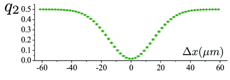
where the parameter is related to in the following way. Let’s consider the path terms in the contribution in , namely . The decoherence acts by (partially) spoiling the coherence between the and term giving the state . By assuming that for the decoherence (14) is the main source of imperfections, the measured visibility222The measured visibility is defined as where are the coincidences measured out of interference (i.e. measured for much longer than the single photon coherence lenght) and the coincidences measured in a given position of . of first interference on BS may be compared with the calculated value : then, the relation between and , shown in Fig. 2, is obtained. It is worth noting that at we have which corresponds to a maximum visibility at .
The decoherence channel (14) acts on the state . However, it can be interpreted as a decoherence acting on the phased Dicke state . Using equation (8) and the relations and , the channel (14) may be interpreted as a collective decoherence channel on :
| (15) |
with , , and . A collective decoherence is a decoherence process that cannot be seen as the action of several channels acting separately on two (or more) qubits. A different type of collective noise, introduced in Macchiavello and Palma (2002), was experimentally demonstrated in Banaszek et al. (2004) for two polarization qubits in optical fibers.
Two other main sources of imperfections must be considered in our setup (see supplementary informations for a detailed discussion): the first one is due to a non perfect superposition between forward and backward SPDC emission, i.e. between the and contributions. This imperfection can be modeled as a phase polarization decoherence channel acting on qubit : . By selecting in the correlated modes and by suitably setting the HWP on the pump beam we obtain the following state: . Even in this case the value of the measured polarization visibility () can be related to the polarization decoherence channel as . The second interference on the BS (i.e. after the Sagnac loop) has been also investigated. In the measurement condition we obtained an average visibility of corresponding to a decoherence channel with .
Measurements - We measured the witness operator (7) for different values of . The results are shown in figure 3. The dark curve corresponds to the theoretical curve obtained by considering all the three described decoherence channels and setting and (see the supplementary informations about the details on the theoretical curve). Notice that the noise parameter for which the witness expectation value vanishes gives a lower bound on the robustness of the entanglement of the produced state with respect to the implemented noise. The witness measured for the phased Dicke state is
| (16) |

We also measured a witness introduced in Töth et al. (2009) to demonstrate that the generated state is a genuine multipartite state and to obtain a bound on the fidelity . Its expression is given in the supplementary informations. We obtained
| (17) |
Following the approach of quantitative entanglement witnesses Eisert et al. (2007), we can also use the experimental result on the expectation value of the witness to provide a lower bound on the random robustness of entanglement . This is defined in Vidal and Tarrach (1999) to be the maximum amount of white noise that one can add to a given state before it becomes separable. A lower bound on is given by
| (18) |
where is the dimension of the Hilbert space on which acts. In our experiment the witness from Eq. (7) and its expectation value given in Eq. (16) lead to
| (19) |
In summary, we have generated phased 4-qubit Dicke states with hyperentangled photons. We demonstrated the implementation of controlled noise via a relative path delay in the interferometer. The multipartite entanglement was detected via a new class of structural entanglement witnesses and the robustness of entanglement was tested by using an intrinsically high phase stability setup. The realized phase Dicke states have a high fidelity and, compared with other Dicke states based on 4-photon entanglement, are produced at higher repetition rate.
This work was supported in part by the EU projects CORNER, DFG project and by Finanziamento Ateneo 2009 of Sapienza Università di Roma.
References
- Barbieri et al. (2005) M. Barbieri, C. Cinelli, P. Mataloni, and F. De Martini, Phys. Rev. A 72, 052110 (2005).
- Kiesel et al. (2007) N. Kiesel, C. Schmid, G. Tóth, E. Solano, and H. Weinfurter, Phys. Rev. Lett. 98, 063604 (2007).
- Prevedel et al. (2009) R. Prevedel, G. Cronenberg, M. S. Tame, M. Paternostro, P. Walther, M. S. Kim, and A. Zeilinger, Phys. Rev. Lett. 103, 020503 (2009).
- Wieczorek et al. (2009) W. Wieczorek, R. Krischek, N. Kiesel, P. Michelberger, G. Tóth, and H. Weinfurter, Phys. Rev. Lett. 103, 020504 (2009).
- Barbieri et al. (2003) M. Barbieri, F. De Martini, G. Di Nepi, P. Mataloni, G. M. D’Ariano, and C. Macchiavello, Phys. Rev. Lett. 91, 227901 (2003).
- Bourennane et al. (2004) M. Bourennane, M. Eibl, C. Kurtsiefer, S. Gaertner, H. Weinfurter, O. Gühne, P. Hyllus, D. Bruß , M. Lewenstein, and A. Sanpera, Phys. Rev. Lett. 92, 087902 (2004).
- Krammer et al. (2009) P. Krammer, H. Kampermann, D. Bruß, R. A. Bertlmann, L. C. Kwek, and C. Macchiavello, Phys. Rev. Lett. 103, 100502 (2009).
- Horodecki et al. (1996) M. Horodecki, P. Horodecki, and R. Horodecki, Phys. Lett. A 223, 1 (1996).
- Terhal (2000) B. M. Terhal, Phys. Lett. A 271, 319 (2000).
- Ceccarelli et al. (2009) R. Ceccarelli, G. Vallone, F. De Martini, P. Mataloni, and A. Cabello, Phys. Rev. Lett. 103, 160401 (2009).
- Vallone et al. (2007) G. Vallone, E. Pomarico, F. De Martini, P. Mataloni, and M. Barbieri, Phys. Rev. A 76, 012319 (2007).
- (12) J. T. Barreiro, P. Schindler, O. Gühne, T. Monz, M. Chwalla, C. F. Roos, M. Hennrich, and R. Blatt, eprint arXiv:1005.1965.
- Macchiavello and Palma (2002) C. Macchiavello and G. M. Palma, Phys. Rev. A 65, 050301 (2002).
- Banaszek et al. (2004) K. Banaszek, A. Dragan, W. Wasilewski, and C. Radzewicz, Phys. Rev. Lett. 92, 257901 (2004).
- Töth et al. (2009) G. Töth, W. Wieczorek, R. Krischek, N. Kiesel, P. Michelberger, and H. Weinfurter, New Journal of Physics 11, 083002 (2009).
- Eisert et al. (2007) J. Eisert, F. G. S. L. Brandao, and K. M. R. Audenaert, New Journal of Physics 9, 46 (2007).
- Vidal and Tarrach (1999) G. Vidal and R. Tarrach, Phys. Rev. A 59, 141 (1999).
I SUPPLEMENTARY INFORMATION
Let’s now describe in more detail the considered decoherence sources. First of all, in our setup, there is a polarization decoherence at the level of the generation due to a non perfect superposition between the and emission. Since is given by the superposition of and terms, our decoherence partially erases the coherence between them but cannot introduce terms containing or . This decoherence can be modeled by a phase decoherence channel acting on polarization qubit :
| (20) |
By exploiting the same arguments used to obtain (15), the channel (20) can be interpreted as a decoherence channel on . Since , the polarization decoherence (20) can be written as
| (21) |
with and . By measuring the visibility of polarization interference we estimated .
The second decoherence affects the path degree of freedom and corresponds to the channel given in eq. (14). We can change the parameter by varying the delay in the first interferometer. If figure 2 we show the relation between the parameter and the path delay .
A third decoherence effect, again in the path degree of freedom, is related to the second interference on the BS. The non-perfect interference can be modeled as a decoherence channel acting exactly as (14). Written in the Kraus representation it reads:
| (22) |
with , , and . By measuring the interference visibility we estimated .
The three decoherence channels can be summarized as follows
| (23) |
From the previous expression, it is possible to calculate the theoretical expectation values of the operators appearing in the witness as a function of the ’s parameters: (7):
| (24) | ||||
For and we obtain the following expectation value for :
| (25) |
This expression is used for the theoretical curve in figure 3.