Organization of Block Copolymers using NanoImprint Lithography: Comparison of Theory and Experiments
Abstract
We present NanoImprint lithography experiments and modeling of thin films of block copolymers (BCP). The NanoImprint technique is found to be an efficient tool not only to align lamellar phases perpendicularly to the substrate, but also to get rid of in-plane defects over distances much larger than the natural lamellar periodicity. The modeling relies on self-consistent field calculations done in two- and three-dimensions, and is found to be in good agreement with the experiments. It also offers some insight on the NanoImprint lithography setup and on the conditions required to perfectly ordered BCP lamellae.
I Introduction
One of the main challenges of contemporary design of microchips is to find affordable techniques of patterning silicon wafers at the nanoscopic level Bang09 . To address this question, self-assembling block copolymers (BCP) have been suggested as potent candidates to provide patterns for nanolithography Black07 ; Kim09 . The aim is to produce thin and structured BCP films with patterns such as lamellae, cylinders and spheres Leibler80 that can then be transferred to a substrate.
When thin films of BCP are cast on a surface, they self-assemble into one of several possible nanostructures having a specific orientation with respect to the substrate. In particular, by adjusting the surface interactions and film thickness, it is possible to produce lamellar and cylindrical phases in an orientation perpendicular Mansky97 ; Liu09 to the substrate. However, while lamellar and cylindrical phases can be perpendicularly aligned on a large scale Ham08 ; Han08 , the ever-remaining challenge for micro-electronic applications is to find affordable and efficient techniques for in-plane organization, with minimal amount of defects. This will allow producing devices that are hundreds of micrometers in size, where precise spatial accessibility is required.
Several attempts have been made to address this challenge. They include, among others, chemical patterning of the substrate by e-beam lithography Ruiz08 ; Stoykovich05 or by prepositioning of another copolymer layer Ruiz07 , and graphoepitaxy Segalman01 , where an artificial surface topography of grooves separated by walls is created on the substrate. Due to such topographical constraints, ordered regions of BCP are obtained over length scales of micrometers Segalman01 ; Park07 ; Cheng02 ; Sundrani02 .
A more recent technique addressing the same issue is the nanoimprint lithography (NIL)Chou95 ; Hu05 ; Li02 ; Kim08 , and it has potential advantages in terms of cost and simplicity. It uses surface micrometer-sized structural features of a reusable mold made by standard lithographic techniques to guide the self-assembly of the BCP at the nanometer scale. In Ref. Li02 a cylindrical phase oriented perpendicularly to the substrate was imprinted by NIL where the NIL patterns are about twice or three times larger than the BCP period. The resulting BCP phase is aligned perpendicularly, but the imprint procedure is found to induce unwanted defects. In another attempt Kim08 , alignment of lamellae was produced by NIL, but the lamellae were not oriented perpendicular to the substrate.
Motivated by previous studies, we attempt in this paper to improve on the NIL procedure. In particular, we focus on NIL setups that produce perpendicular aligned lamellae with no defects, even when the NIL structural features are much larger than the BCP period.
II Materials and methods
The symmetric di-block copolymer polystyrene-b-polymethylmethacrylate (PS52K-b-PMMA52K, PDI:1.09) was purchased from Polymer Source Inc and exhibits a lamellar phase of period = 49 nm in the bulk Stoykovich05 . PS and PMMA blocks share very similar values of surface tensions, in the range of 29.7 mN/m – 29.9 mN/m and 29.9 mN/m – 31 mN/m, respectively, at the temperatures used for film annealing (170∘C). The glass transition temperature of PS and PMMA is 100∘C and 105∘C, respectively.
UV/ozone apparatus was used both for wafer cleaning and octadecyl-trichlorosilane (OTS) self-assembly monolayer (SAM) oxidation. The wafers were cleaned by irradiation before the silanization treatment. The OTS SAM oxidation was performed as described in Ref. Liu09 in order to reach a precise surface energy. To get a better contrast during AFM imaging, selective phase etching of PMMA can be applied just before the imaging. To avoid ozone formation that would degrade both the PS and PMMA blocks, the reaction chamber was flushed for 30 min with nitrogen before and during UV-irradiation. Samples were then irradiated for 30 min and subsequently treated with glacial acetic acid during 1h to ensure complete removal of degraded PMMA fragments.
Solutions of 1 wt% of BCP in toluene were prepared and spin coated at 1800 rpm onto silanized silicon wafers to produce BCP films with thickness of about 40 nm (below ). Subsequently, the samples were annealed in a vacuum oven at 170∘C at a pressure of less than 3 KPa for 1 day. The resulting lamellar phase was examined and found to be perpendicular to the neutral substrate but with many in-plane defects Liu09 . Then, the sample was treated by thermal NIL, which consists of embossing the thin BCP film, heated above its glass transition temperature, by a reusable mold made of a series of grooves as is shown schematically in Fig. 1(a).
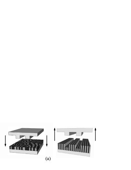

Imprint experiments have been carried out at the CEA/LETI clean room in Grenoble, France, using a EVG®520HE press. The mold is a 4” silicon wafer with topographical features made of grooves of tens of nanometers in height with groove width () and inter-groove separation () in the range of hundreds of nanometers [Fig. 1(b)]. The mold surface is coated with a perfluorinated polymer layer to avoid BCP adhesion. An overall pressure of about MPa was applied to the BCP film, first at a temperature of 120∘C during 7 hours, then at 170∘C during 60 hours.
Surface imaging after imposing NIL on the BCP film was performed by SEM and AFM. SEM imaging was performed with a Hitachi 9300 apparatus, operated at optimal voltages of about 500 V. This voltage allows observation of BCP phase organization, without PMMA etching, due to a smaller penetration depth of the electron beam and enhanced secondary electron emission yield. AFM imaging has been performed using a NanoScope V (Digital Instruments). The samples were analyzed using the AFM tapping mode in air and with silicon cantilevers of 125 m in length (Ultrasharp, Micro Masch). Their resonance frequency ranges between 265 and 400 KHz, whereas their force constant lies in between 20 - 75 N/m and the tip radius of curvature is less than 10 nm. The scan rate was chosen in order to obtain the best contrast in phase images and the least deviation between height trace and retrace scans.
III The Self-Consistent Field theory
We use self-consistent field (SCF) theory to investigate the behavior of a melt of A-B di-block copolymer (BCP) film at nano-patterned surfaces. The BCP film has polymer chains, each having a length in terms of the Kuhn length , which is assumed, for simplicity, to be the same for the and monomers. Hence, the A-monomer molar fraction is equal to its volume fraction. In addition, hereafter we concentrate on symmetric di-BCP, having . The symmetric BCP yields thermodynamically stable lamellar phases of periodicity , as temperature is lowered below the order-disorder temperature (ODT). We rescale all lengths, , by the natural periodicity of the BCP, , where is the chain radius of gyration . Similarly, the curvilinear coordinate along the chain contour, , is rescaled by , yielding . With these conventions, the free energy for such a BCP film confined between the two surfaces is
| (1) | |||||
The system has a total rescaled volume . The closed-packing density (monomer per unit area) is , and the Flory-Huggins parameter is . The dimensionless volume fractions of the two components are defined as and , respectively, whereas , , are the auxiliary fields coupled with , and is the single-chain partition function in the presence of the and fields. The third term represents a surface-energy preference, where and are the short-range interaction parameters of the surface with the A and B monomers, respectively. Formally, and are surface fields and have non-zero values only on the surface(s). It is worth noting that due to the above rescaling, the variables in Eq. (1) should also be rescaled by: , and .
Finally, the last term in Eq. (1) includes a Lagrange multiplier introduced to ensure the incompressibility condition of the BCP melt:
| (2) |
By inserting this condition, Eq. (2), in the surface free energy term of Eq. (1), the integrand becomes . Hence, is the only needed surface preference field to be employed hereafter.
Using the saddle-point approximation, we can obtain a set of self-consistent equations
| (3) | |||||
| (4) | |||||
| (5) | |||||
| (6) |
where the incompressibility condition, Eq. (2), is obeyed, and the single-chain free energy is:
| (7) |
The two types of propagators and (with ) are solutions of the modified diffusion equation
| (8) |
with the initial condition , and . This diffusion equation is solved using reflecting boundary conditions at the two confining surfaces ( and ): and , while periodic boundary conditions are used in the perpendicular direction.
The top surface with parallel and elongated grooves is modeled as an impenetrable boundary for the polymer chains. In practice, this is done by assigning a large value to the local surface field, , for all points inside the grooves. In addition, on the whole top surface we include a weak attractive field (), which takes into account the preferred surface interaction with the A block.
We use the same numerical method as that in our previous work Manxk10 to solve these self-consistent equations. Fields and densities were calculated on a grid with a spatial resolution of or for the three- and two-dimensional grids, respectively. First, we guess an initial set of values for the auxiliary fields. Then, through the diffusion equations we calculate the propagators, and , and from Eq. (5) and Eq. (6) we calculate the monomer volume fractions . Next, a new set of values for is obtained through Eq. (3) and Eq. (4) and this procedure can be iterated until convergence is obtained by some conventional criterion. More details are given in Ref. Manxk10 .
IV Results
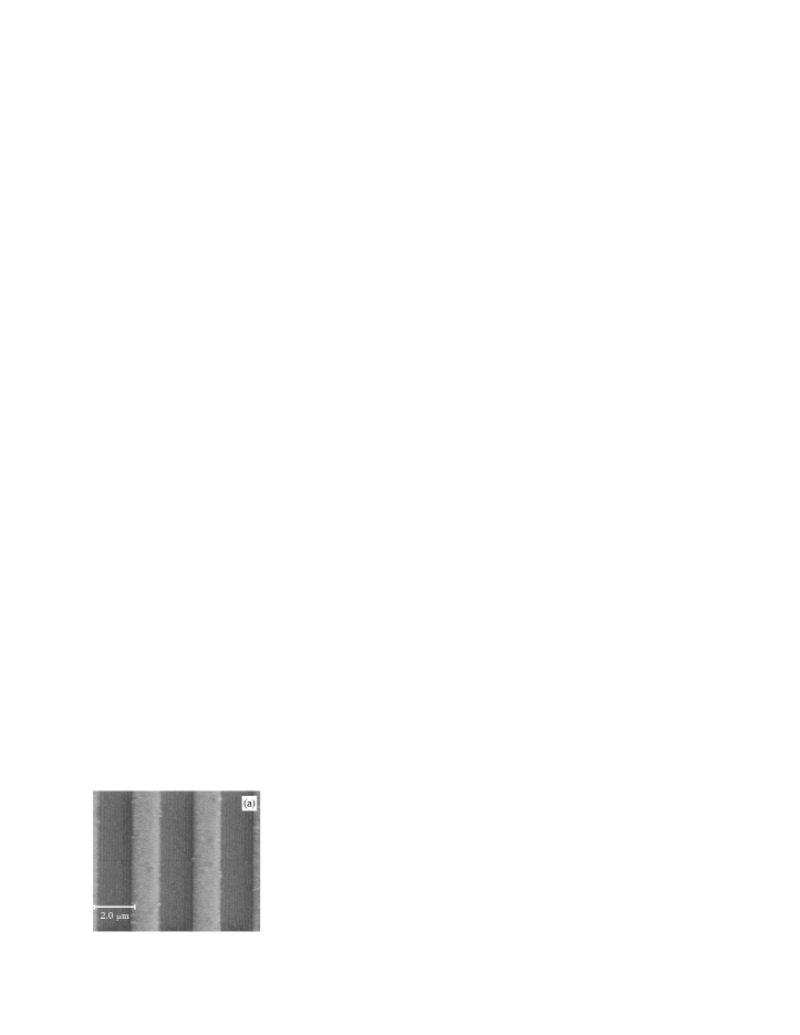
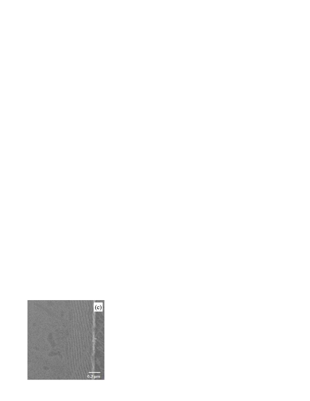
Figure 2 shows a top view of SEM and AFM images of a PS52K-b-PMMA52K thin film after nanoimprinting with a mold made of a series of parallel grooves [Fig. 1]. From the images, it can be seen that the lamellar phase is indeed oriented perpendicular to the bottom substrate. Moreover, in Fig. 2(a) the SEM image indicates that the thicker sections of the BCP film exhibit lamellae that are nicely oriented in a parallel fashion along the groove vertical walls (the -direction), while the thinner sections of the film are too thin to be visualized by the SEM technique. The same in-plane ordered lamellae are shown as an enlargement in Fig. 2(b), whereas in Fig. 2(c) the region close to the groove vertical wall is visualized by an AFM technique. The AFM image indicates a different in-plane ordering of the thick and thin sections of the BCP film. While the thick section (right) shows well ordered lamellae of periodicity very close to the bulk one, , which are aligned by the wall, the lamellae of the thin section (left) of the film are less oriented and contain some defects. This observation can be attributed to the preferred interaction of the mold vertical walls with one of the two BCP blocks. The lamellar film to the right of the wall is thicker in the -direction (height as in Fig. 1(b)) and is in contact with the vertical groove wall, while the film section on the left has a smaller height (), and the wall has no direct influence on it.

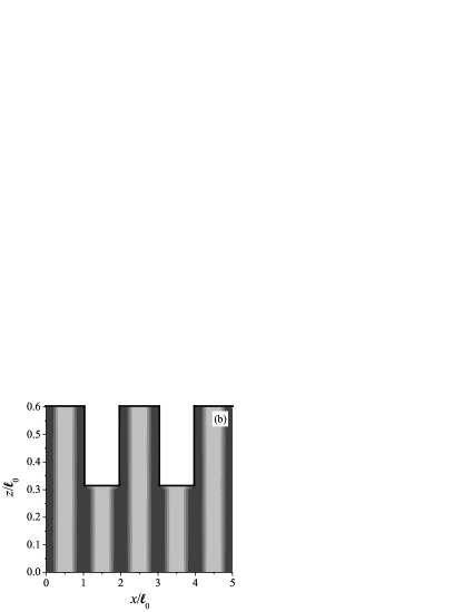
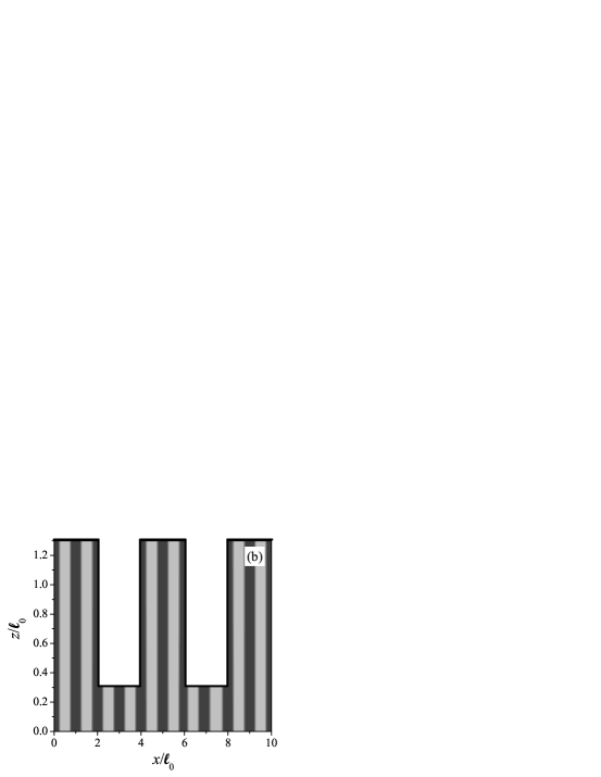
In order to further understand these NIL results, we complement the experiments with self-consistent field (SCF) theory calculations performed on symmetric BCP lamellar phases Matsen97 ; Petera98 ; Pereira98 ; Geisinger99 ; Tsori01 . The NIL setup is modeled by BCP lamellae having a natural periodicity , and confined in the -direction between a flat and neutral bottom surface () at and a topographical varying surface (the top mold), as is shown schematically in Fig. 1(b). The top surface has the form of elongated grooves (in the -direction) of square cross section (in the -direction). The down-pointing indentations (fingers) have a width of separated by grooves with a cross-section width . The BCP film thickness measured with respect to the surface varies between inside the grooves and in between the grooves [Fig. 1(b)]. The mold preferential interaction toward one of the two blocks is modeled by an overall non-zero surface field, .
We performed several three dimensional (3d) SCF calculations to shed light on the film in-plane ordering. The 3d system size is , where is set to be less than one BCP periodicity in accord with the experiments (Fig. 2). In our 3d SCF calculations, a gradual temperature quench is performed. The starting temperature is above the order-disorder temperature (ODT), ; hence, inside the BCP disordered phase. The temperature is then gradually decreased (or, equivalently, the value of is gradually increased) until the system reaches , which is well below the ODT.
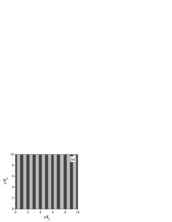
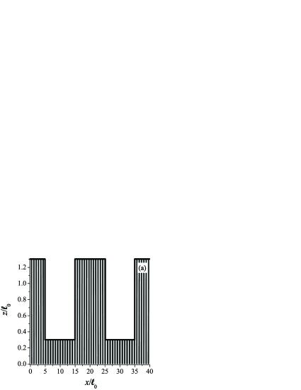
With the simulated NIL mold, a perfect perpendicular lamellar structure is found and is shown in Fig. 3(a) as a top-view cut at , and in 3(b) as a side cut at . Note that in the calculation, Fig. 3(a), the thinner and thicker sections of the film are equally ordered, whereas in the experiments, Fig. 2(c), the in-plane ordering is not as good for the thinner section of the film (left side of the figure) as compared with the thicker film section on the right side. This lack of in-plane ordering in the experiments might be due to lack of equilibration or shear effects at the walls, and more detailed investigations are needed to further clarify this point.
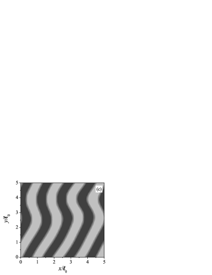
As a further check, we compare the NIL setup with a BCP film confined between two neutral and flat surfaces. As can be seen in Fig. 3(c), a perpendicular lamellae structure arises with no in-plane ordering when the same gradual temperature quench process is repeated for the neutral and flat surfaces. It is clear that there are many in-plane defects in this case, in contrast with the NIL mold that induces a strong in-plane ordering.
We show another 3d calculation in Fig. 4, for which all the parameters are the same as in Fig. 3 (a) except that we modify the value to be . We still obtain the perfect perpendicular lamellae for this thicker BCP film, which is consistent with the phase diagram of Ref Manxk10 . We conclude that the value of is not strictly limited, but can have a range of values that will result in a perfect BCP perpendicular lamellar phase.
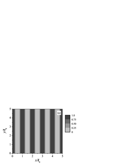
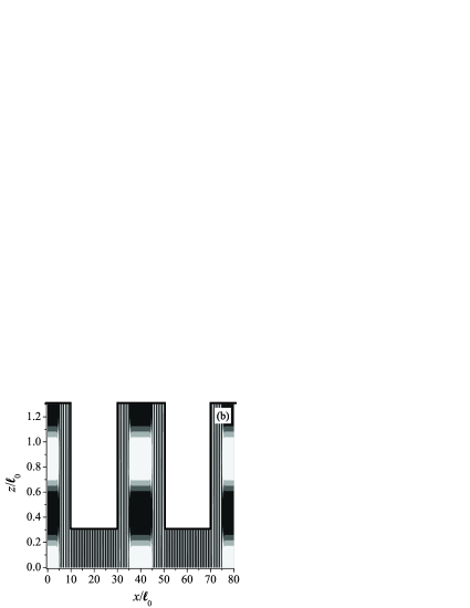
Another important question we addressed is the stability of the perpendicular phase for wider grooves (larger ). To further explore this issue we complemented the 3d calculations by 2d ones where much larger lateral system sizes (up to ) can be simulated. Although the two-dimensional calculation cannot infer on the degree of in-plane ordering and defects, it is of value because it shows the effects of groove width on the stability of the perpendicular BCP lamellae. In Fig. 5(a), an ordered perpendicular phase is found for the NIL setup with . This figure should be compared with the 3d calculations as shown in Fig. 3(a) for much narrower grooves of .
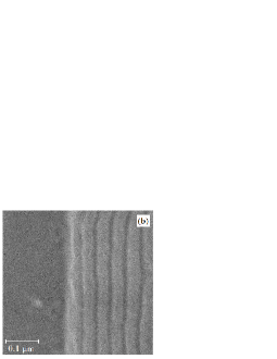
The NIL setup has some limitations as can be seen from our calculations and through preliminary experimental results. If we increase the groove periodicity (scaling up both and ), the perfect perpendicular lamellae do not persist. Instead, the film breaks up into a mixed morphology, combining a perpendicular phase close to the groove wall with a parallel phase induced by the horizontal section of the top surface. This can be seen in Fig. 5(b), where all parameters are the same as in 5(a) beside a larger groove periodicity, . These findings are in accord with the experimental ones shown in Fig. 5(c), where SEM images demonstrate the loss of the perpendicular lamellae, for large enough groove periodicity, after distances of about from the groove wall.
V Discussion & Conclusions
We address in this article the influence of nano-patterning of surfaces on the orientation and alignment of lamellar phases of BCP films, using a NIL technique to produce superior perpendicular ordering. The main goal of the NIL is to be able to use surface features on length scales larger than the BCP natural periodicity in order to reduce the cost of expensive surface preparation treatments.
The effect of the NIL setup on BCP in-plane ordering is clearly demonstrated both in the experiments and in the modeling. Without the NIL mold, it is possible to obtain perpendicular lamellae but with many in-plane defects which cannot be annealed away. However, with the NIL mold, wetting of the vertical groove wall induces perfect perpendicular ordering with minimal amount of defects, over large lateral distances.
In our model the perfect perpendicular order is induced by a small surface field , chosen to agree with PS-PMMA experimental setup, where the relative difference in the surface tension between the two blocks and the surface is about 1%. The value of is limited by two opposing trends. On the one hand, should be large enough so that one of the two blocks would wet the groove vertical wall. On the other hand, should be small enough in order not to interfere with the overall perpendicular ordering.
Another conclusion from the present study is that the NIL groove periodicity cannot be much larger than ; otherwise the BCP perpendicular order is lost [see Fig. 5(b) and (c)], where the perpendicular order is lost for about .
Our SCF calculations are in good agreement with the presented experiments, and provide some insight into the conditions needed to obtain perpendicular lamellar phases with minimal amount of in-plane defects. We hope that in the future more detailed three-dimensional calculations as well as careful investigations of film rheology will shed more light on the fundamental behavior as well as applications of BCP films in presence of nano-patterned surfaces.
Acknowledgements
The help of S. Niedermayer in sample preparation is gratefully acknowledged. We would like to thank the Triangle de la Physique, France (POMICO project No. 2008-027T) for supporting the visits of DA and XM to Saclay. This work was supported in part by the U.S.-Israel Binational Science Foundation under Grant No. 2006/055, the Israel Science Foundation under Grant No. 231/08, the Center for Nanoscience and Nanotechnology at Tel Aviv University and the CEA (France) under programs “Chimtronique” and “Nanosciences”.
References
- (1) Bang, J.; Jeong, U.; Ryu, D. Y.; Russel, T. P.; Hawker, C. J. Adv. Mater. 2009, 21, 4769.
- (2) Black, C. T.; Ruiz, R.; Breyta, G.; Cheng, J. Y.; Colburn, M. E.; Guarini, K. W.; Kim, H. C.; Zhang, Y. IBM J. Res. & Dev. 2007, 51, 605.
- (3) Kim, H.-C.; Park, S.-M.; Hinsberg, W. D. Chem. Rev. 2009, 110, 146.
- (4) Leibler, L. Macromolecules 1980, 13, 1602.
- (5) Mansky, P.; Liu, Y.; Huang, E.; Russell, T. P.; Hawker, C.-J. Science 1997, 275, 1458.
- (6) Liu, P. H.; Thébault, P.; Guenoun, P.; Daillant, J. Macromolecules 2009, 42, 9609.
- (7) Ham, S.; Shin, C.; Kim, E.; Ryu, D. Y.; Jeong, U.; Russell, T. P.; Hawker, C. J. Macromolecules 2008, 41, 6431.
- (8) Han, E.; Stuen, K. O.; La, Y.-H.; Nealey, P. F.; Gopalan, P. Macromolecules 2008, 41, 9090.
- (9) Ruiz, R.; Kang, H. M.; Detcheverry, F. A. Dobisz, E.; Kercher, D. S. Albrecht, T. R.; de Pablo, J. J.; Nealey, P. F. Science 2008, 321, 936.
- (10) Stoykovich, M.; Müller, M.; Kim, S.; Solak, H.; Edwards, E.; de Pablo, J. J.; Nealey, P. Science 2005, 308, 1442.
- (11) Ruiz, R.; Sandstrom, R. L.; Black, C. T. Adv. Mater. 2007, 19, 587.
- (12) (a) Segalman, R.; Yokoyama, H.; Kramer, E. Adv. Mater. 2001, 13, 1152. (b) Stein, G. E.; Lee, W. B.; Fredrickson, G. H.; Kramer, E. J.; Li, X.; Wang, J. Macromolecules 2007, 40, 5791.
- (13) Park, S. M.; Stoykovich, M. P.; Ruiz, R.; Zhang, Y.; Black C. T.; Nealey, P. E. Adv. Mater. 2007, 19, 607.
- (14) (a) Cheng, J. Y.; Ross, C. A.; Thomas, E. L.; Smith, H. I.; Vancso, G. J. Appl. Phys. Lett. 2002, 81, 3657. (b) Chuang, V. P.; Cheng, J. Y.; Savas, T. A.; Ross, C. A. Nano Lett. 2006, 6, 2332.
- (15) (a) Sundrani, D.; Sibener, S. J. Macromolecules 2002, 35, 8531. (b) Sundrani, D.; Darling, S. B.; Sibener, S. J. Nano Lett. 2004, 4, 273.
- (16) Chou, S.; Krauss, P.; Renstrom, P. Appl. Phys. Lett. 1995, 67, 3114.
- (17) Hu, Z.; Baralia, G.; Bayot, V.; Gohy J.; Jonas, A. Nano Lett. 2005, 5, 1738.
- (18) Li, H.; Huck, W. Curr. Op. Solid State Mat. 2002, 6, 3; Li H.; Huck, W. Nano Lett. 2004, 4, 1633.
- (19) Kim, S.; Lee, J.; Jeon, S.-M.; Lee, H. H.; Char K.; Sohn, B.-H. Macromolecules 2008, 41, 3401.
- (20) Matsen, M. W.J. Chem. Phys. 1997, 106, 7781.
- (21) Petera, D.; Muthukumar, M. J. Chem. Phys. 1998, 109, 5101.
- (22) Pereira, G. G.; Williams, D. R. M. Europhys. lett. 1998, 44, 302.
- (23) Geisinger, T.; Mueller, M.; Binder, K. J. Chem. Phys. 1999, 111, 5241.
- (24) Tsori Y.; Andelman, D. Eur. Phys. J. E. 2001, 5, 605.
- (25) Man, X. K.; Andelman, D.; Orland, H. Macromolecules 2010, 43, 7261.
for Table of Contents use only
Organization of Block Copolymers using NanoImprint Lithography:
Comparison of Theory and Experiments
Xingkun Man, David Andelman, Henri Orland, Pascal Thébault,
Pang-Hung Liu,Patrick Guenoun, Jean Daillant, Stefan Landis