Geostrophic balance preserving interpolation in mesh adaptive shallow-water ocean modelling
Abstract
The accurate representation of geostrophic balance is an essential requirement for numerical modelling of geophysical flows. Significant effort is often put into the selection of accurate or optimal balance representation by the discretisation of the fundamental equations. The issue of accurate balance representation is particularly challenging when applying dynamic mesh adaptivity, where there is potential for additional imbalance injection when interpolating to new, optimised meshes.
In the context of shallow-water modelling, we present a new method for preservation of geostrophic balance when applying dynamic mesh adaptivity. This approach is based upon interpolation of the Helmholtz decomposition of the Coriolis acceleration. We apply this in combination with a discretisation for which states in geostrophic balance are exactly steady solutions of the linearised equations on an -plane; this method guarantees that a balanced and steady flow on a donor mesh remains balanced and steady after interpolation onto an arbitrary target mesh, to within machine precision. We further demonstrate the utility of this interpolant for states close to geostrophic balance, and show that it prevents pollution of the resulting solutions by imbalanced perturbations introduced by the interpolation.
keywords:
Shallow-water equations; Finite element method; Discontinuous Galerkin, Geostrophic balance; Interpolation; Helmholtz decomposition, ,
1 Introduction
It has been recognised in previous work on shallow-water modelling that the accurate representation of physical balance by the discrete system is of crucial importance. In Le Roux et al. (1998) a number of shallow-water finite element pairs are compared, and it is concluded that the majority of those tested are unable to represent physical balance accurately while simultaneously remaining free of spurious numerical modes. In Cotter et al. (2009b) a finite element pair is presented using a piecewise linear discontinuous element for velocity and a piecewise quadratic continuous element for layer thickness: the finite element pair. This is shown to be free of spurious pressure modes (Cotter et al., 2009b, a) and, in Cotter et al. (2009a) in the context of shallow-water modelling, is shown to have the property that geostrophically balanced states with a constant stream function on the boundary are exactly steady solutions of the discrete linearised shallow-water equations on an -plane. The element pair is compared against a number of other low order discontinuous methods in Comblen et al. (2009), and found to be the most accurate choice amongst those tested. This discretisation is extended in Cotter et al. (2009b, a) to form a family of related finite element pairs, all of which are free of pressure modes and exhibit this optimal balance property.
This paper is concerned with the application of dynamic mesh adaptivity to shallow-water ocean modelling. Dynamic mesh adaptivity allows the resolution of the computational mesh to be varied locally as a simulation develops, in order to resolve dynamically important regions of the flow and thereby increase the accuracy per degree of freedom of a model. While this has the potential for enabling numerical simulations of otherwise inaccessible systems, it presents an additional problem: as well as the possibility of imbalance injection in the numerical discretisation of the underlying equations, there is also a potential for imbalance injection by the mesh optimisation procedure itself.
Recently, dynamic mesh adaptive ocean modelling has been proposed by Pain et al. (2005); Piggott et al. (2008a). This approach utilises unstructured meshes in all three dimensions with dynamic mesh adaptivity applied using element-wise topological operations and nodal perturbations to optimise the mesh according to a metric derived from the interpolation error of simulation fields (Pain et al., 2001; Piggott et al., 2006; Munday et al., 2010). A feature of this approach is that, in each mesh adapt, the new optimised target mesh has, in general, no relationship to the original donor mesh, other than that each is some covering simplex partitioning of the same original domain. This generality presents a particularly challenging interpolation problem.
The Galerkin projection of fields between arbitrary two and three dimensional meshes is described in Farrell et al. (2009); Farrell (2009). This projection is (by definition) optimal in the least squares sense, and has the advantage that the integral of the projected field is exactly conserved. However, there is no guarantee that the projection injects no additional imbalance. In St-Cyr et al. (2008) statically refined mesh and uniform mesh simulations are compared in an adaptive mesh refinement (AMR) shallow-water model of a geostrophically balanced flow. It is noted that there is an increase in the error in the statically refined case, attributed to interpolation errors in the AMR ghost cells which “introduce slight disturbance” in this region, with the resulting errors growing faster in regions of stronger solution gradients. It is suggested that higher order schemes be used to mitigate this.
In this paper we seek to address the problem of imbalance injection by interpolation between arbitrary unstructured meshes. In the context of shallow-water modelling, we formulate an interpolant that, for the linearised system on an -plane, guarantees that flows that are initially steady and in geostrophic balance remain steady and in balance after interpolation onto an arbitrary target mesh.
2 Formulation
In section 2.1 the finite element discretisation of the linearised shallow-water equations using the finite element pair is outlined. A set of properties for geostrophic balance preserving interpolants is presented in section 2.2 for which, for the linearised system on an -plane, an initially steady and geostrophically balanced state remains steady and balanced after interpolation onto an arbitrary target mesh. An interpolant satisfying these properties is given in section 2.3
2.1 Discretised shallow-water equations
The linearised shallow-water equations with free slip boundary conditions are:
| (1a) | |||
| (1b) | |||
| (1c) |
where is the (horizontal) velocity, is the mean layer thickness, is the deviation of the layer thickness from , is the Coriolis parameter, is the gravitational acceleration and is a unit normal on the boundary . From this one may define two non-dimensional parameters: the Rossby number and the Froude number , where and are characteristic flow speeds and spatial scales respectively.
Multiplying equations (1a) and (1b) by test functions and respectively, integrating over the domain , integrating by parts and applying the free slip boundary condition yields the weak form:
| (2a) | |||
| (2b) |
Choosing some simplex covering partition of (the mesh), restricting and to be piecewise linear discontinuous and restricting and to be piecewise quadratic continuous completes the spatial discretisation:
| (3a) | |||
| (3b) |
where denotes the finite element approximation for . Introducing basis function expansions of , , and , this can be re-expressed as:
| (4a) | |||
| (4b) |
where and are the nodal values for velocity and layer thickness respectively and:
| (7) |
and are the velocity space and layer thickness space mass matrices respectively, and is the discrete divergence matrix:
| (8) |
2.2 Geostrophic balance preserving interpolants
Consider interpolation between a donor mesh and a target mesh . Let and denote “on donor” and “on target” respectively - for example and are the divergence matrices, as per (8), assembled on the donor and target meshes respectively. Consider an interpolation procedure as follows:
-
1.
Perform a Helmholtz decomposition of the Coriolis acceleration on the donor mesh:
(9) for some scalar potential and discrete divergence free .
-
2.
Interpolate , and from the donor to the target to form , and , using interpolants with the following properties:
(10a) (10b) (10c) -
3.
Recompose from and :
(11)
The Helmholtz decomposition splits the Coriolis acceleration into a curl-free scalar potential gradient component and a divergence free residual (Weyl, 1940; Ladyzhenskaya, 1969). Only the scalar potential gradient component can be cancelled from equation (4a) by a layer thickness gradient. For incompressible Navier-Stokes, this scalar potential gradient component must be exactly cancelled by the pressure gradient, with the diagnostic pressure field acting as a Lagrange multiplier via which the incompressibility constraint is applied.
Property (10b) states the somewhat trivial requirement that zero is preserved by the interpolant for . Property (10c) couples the velocity and layer thickness interpolation, and can be achieved if and use the same interpolant and that interpolant is scale invariant. Property (10a) asserts that the interpolant for preserves zero tangential gradients on the domain boundary, and is required in order to avoid generation of grid scale boundary Kelvin waves by the interpolation.
We now proceed to prove that this interpolant, when applied to a discretisation of the linearised shallow-water equations on an -plane, guarantees that a steady and geostrophically balanced state on the donor mesh results in a state that is steady and balanced on the target mesh. By definition, for a geostrophically balanced state on the donor:
| (12) |
By equation (9) and , and hence by properties (10b) and (10c) and . Hence, by equation (11), on the target:
| (13) |
Also, since is perpendicular to :
From (Cotter et al., 2009a), if using the element pair on an -plane:
| (15) |
2.3 Implementation and boundary conditions
The Helmholtz decomposition of the Coriolis acceleration on the donor mesh is equivalent to the pressure projection method commonly used for incompressible Navier-Stokes solvers (Chorin, 1967; Temam, 1968; Gresho, 1990). Multiplying equation (9) by and using leads to the elliptic equation:
| (16) |
Note that here the consistent mass matrix can be used as the mass matrix is block diagonal, and hence the Laplacian matrix is sparse. From this and can be determined. Following interpolation of the Helmholtz decomposition can be diagnosed directly from and via equation (11). Therefore, the key step in forming a geostrophic balance preserving interpolant is to choose interpolants for , and such that the properties (10a), (10b) and (10c) are satisfied.
One simple approach is to apply a Galerkin projection of from the donor mesh to the target mesh, as described in Farrell et al. (2009), and to interpolate and using collocation: evaluation of the donor fields at the nodal coordinates of the target mesh. Since Galerkin projection and collocation are linear, properties (10b) and (10c) are satisfied. Collocation also preserves constant boundary values, and hence property (10a) is satisfied. However, collocation (at least for piecewise linear fields) erodes solutions bounds and has no optimality properties (Farrell, 2009).
A more accurate approach is to apply a mesh-to-mesh Galerkin projection of and . This does not in general satisfy property (10a), although this issue can be resolved by using a further decomposition of , with an equivalent decomposition of in order to satisfy property (10c). Assuming is simply connected, can be decomposed into:
| (17) |
where is equal to some constant on the boundary, and is some residual. can be re-expressed:
| (18) |
Here and satisfy:
| (19a) | |||
| (19b) |
where is the discrete Laplacian matrix , is with a Dirichlet boundary condition of zero on and is with a Dirichlet boundary condition of one on . Minimising subject to (17) then yields a unique value for :
| (20) |
This choice of has the property that if is constant on , then . Applying a Galerkin projection of and from the donor mesh to the target mesh, with a Dirichlet boundary condition of on for , therefore guarantees that the boundary property (10a) is satisfied.
Note that using the mass matrix in place of the Laplacian matrix, , is not suitable here, as this results in non-smooth and , with strong gradients close to the boundary which can generate significant noise in the donor-to-target Galerkin projection.
The full geostrophic balance preserving interpolation procedure is therefore:
-
1.
Compute from .
- 2.
- 3.
-
4.
Apply a Galerkin projection from the donor mesh to the target mesh of , , , and , with Dirichlet boundary conditions for and as determined from equation (20), to form , , , and .
-
5.
Compute from and using equation (17). Similarly compute from and .
-
6.
Compute using equation (11).
-
7.
Compute from .
3 Numerical Examples
In this section several numerical examples of geostrophic balance preservation using the interpolation procedure presented above are given. In section 3.1 it is demonstrated that the geostrophic balance preserving interpolant ensures that a steady and balanced state remains steady and balanced after interpolation. In section 3.2 a state close to geostrophic balance is considered, and it is shown that the geostrophic balance preserving interpolant avoids imbalance injection. The interpolant is applied to a Kelvin wave in section 3.3, and the accuracy of the interpolant in the norm is quantified in section 3.4.
3.1 Preservation of balance
The linearised shallow-water equations (4a) and (4b) on an -plane were discretised in time using Crank-Nicolson finite differencing (Crank and Nicolson, 1947), and the linear systems solved with preconditioned conjugate gradients using the PETSc library (Balay et al., 1997, 2008, 2009). Further details of the discretisation are given in Cotter et al. (2009a).
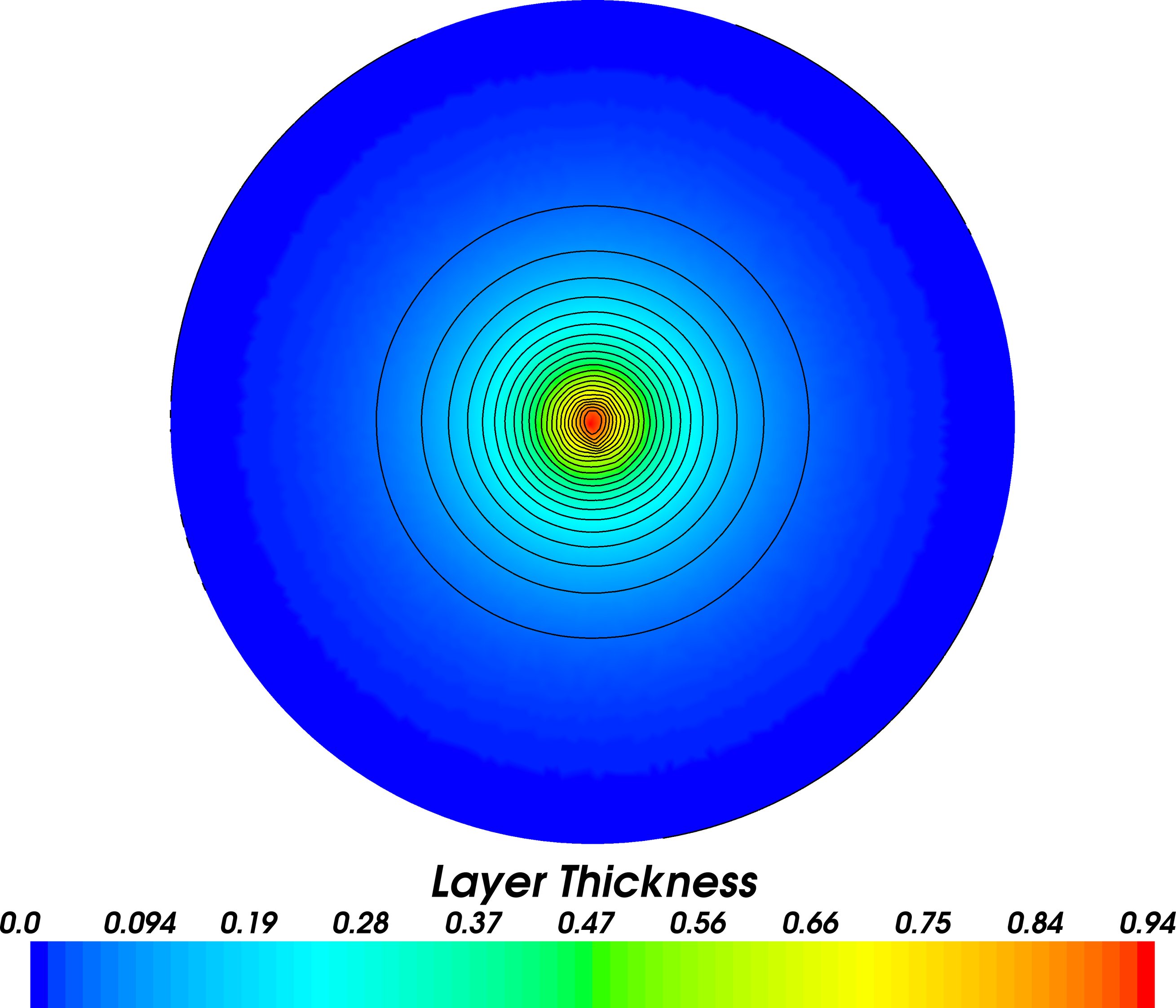
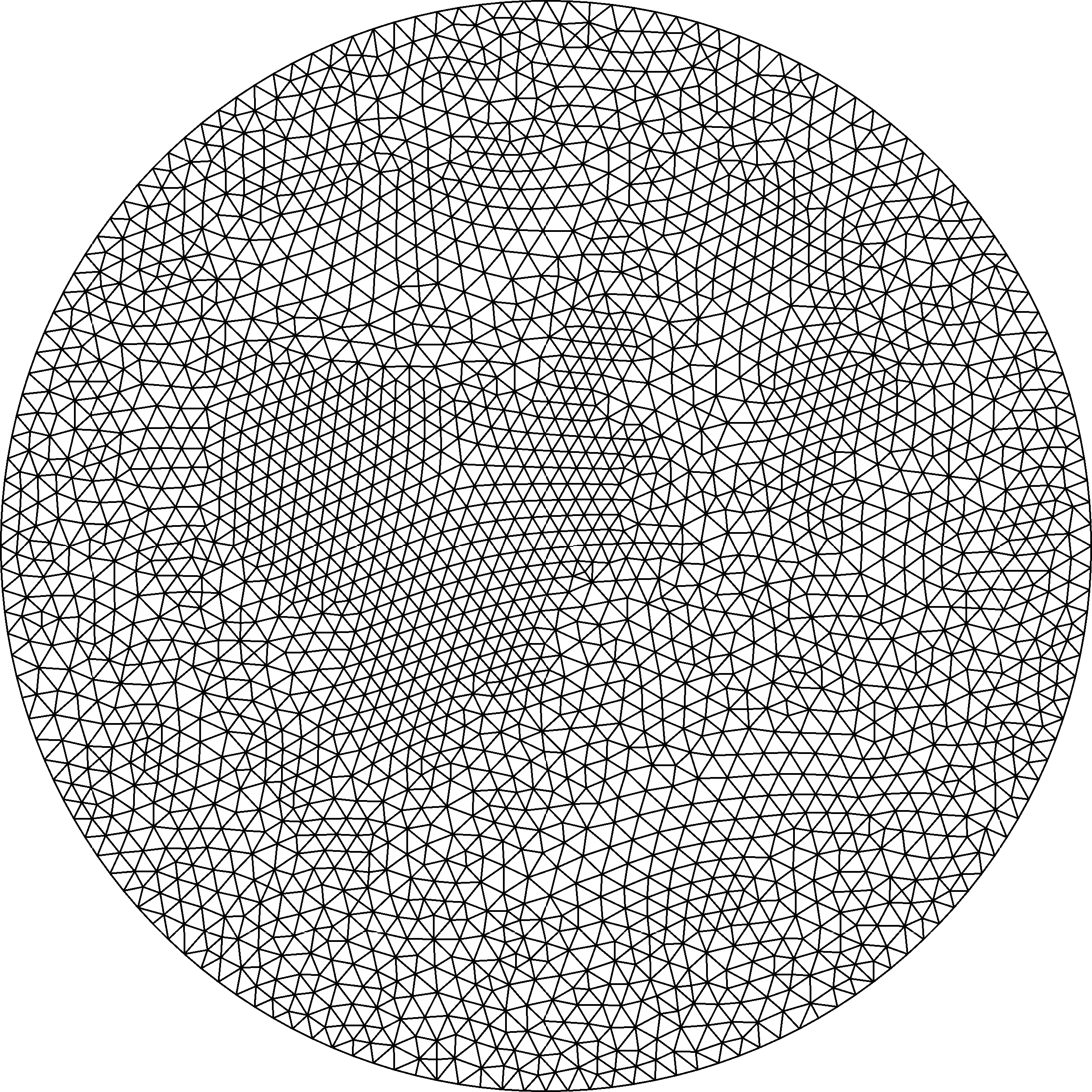
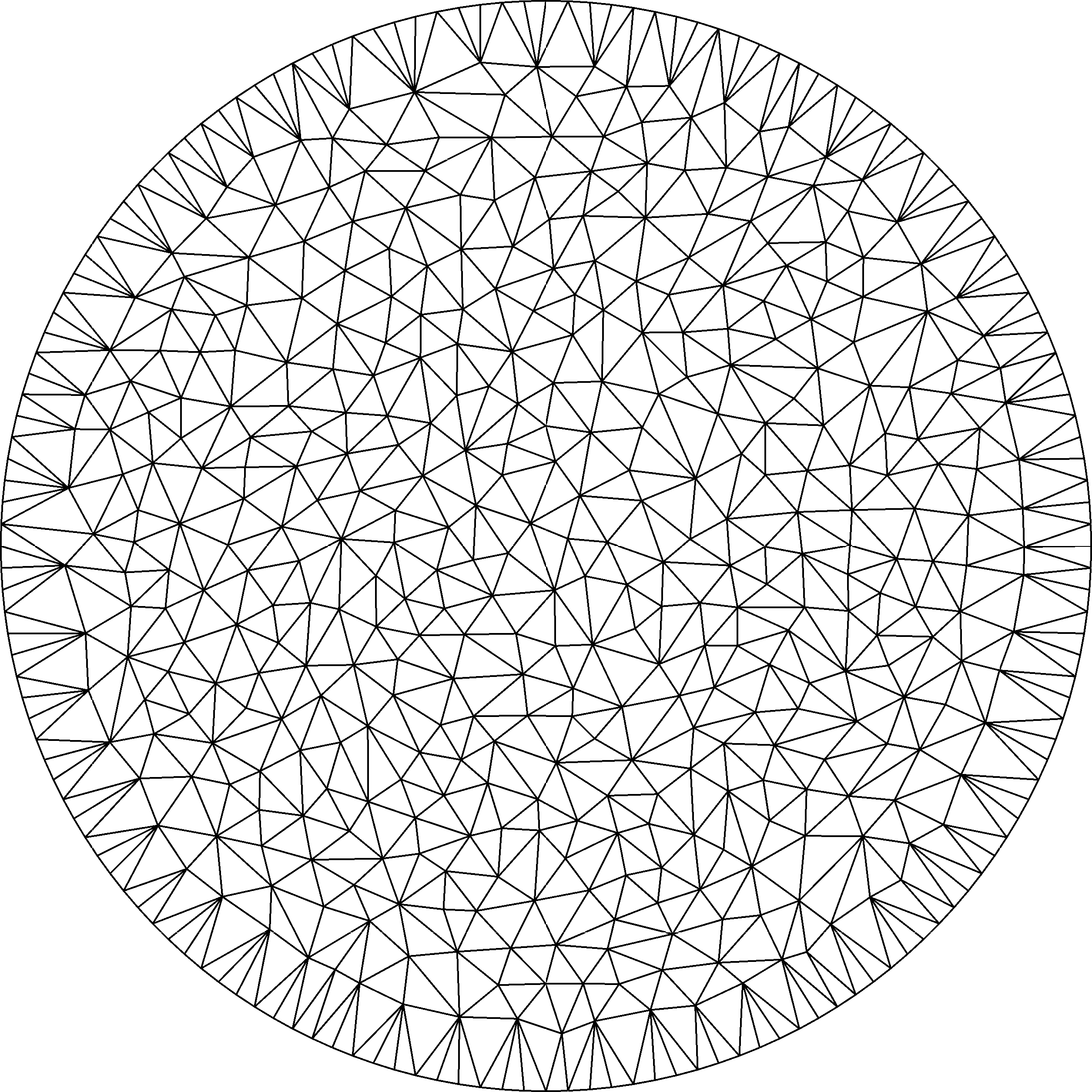
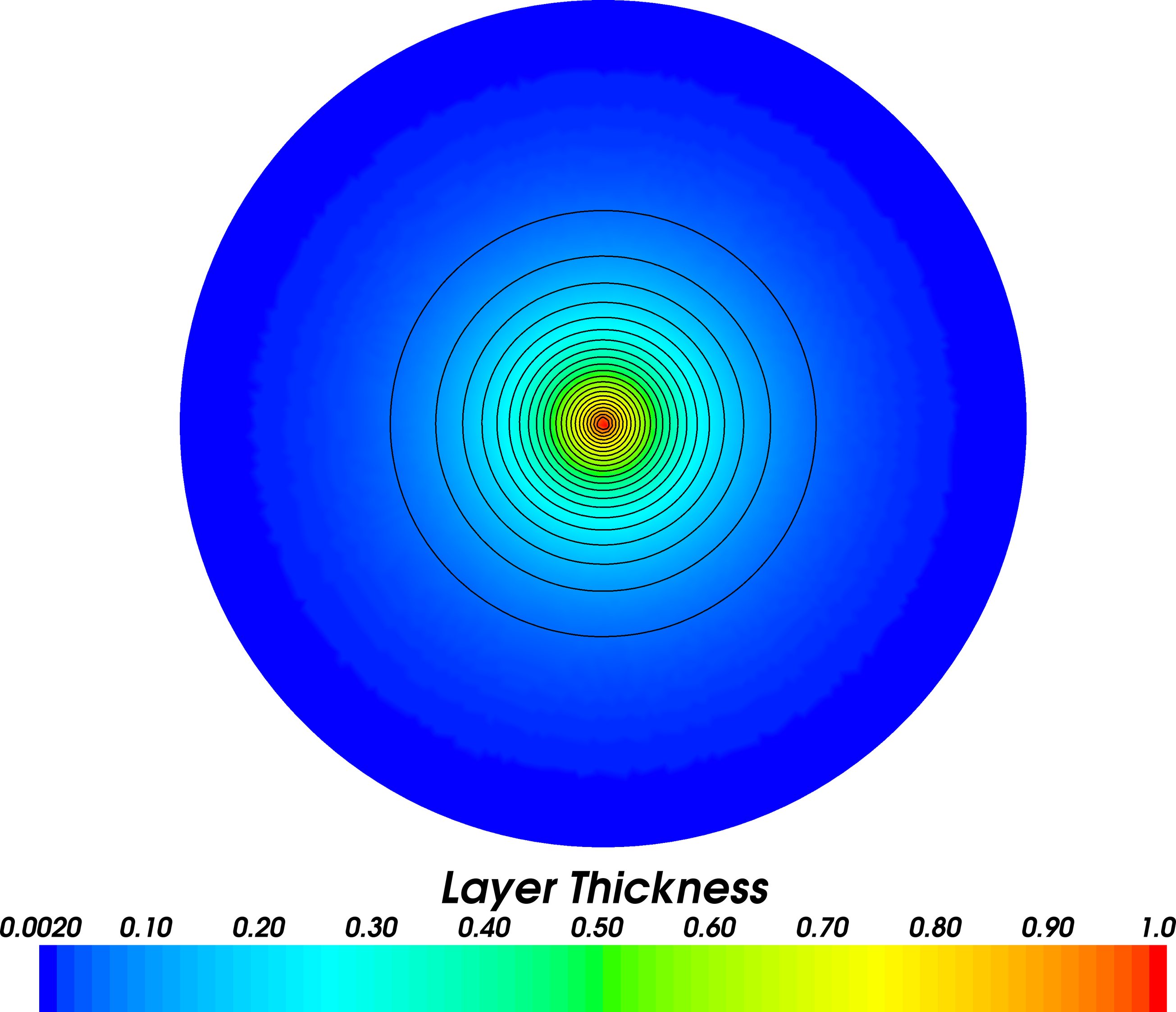
In order to test for imbalance injection by mesh-to-mesh interpolation, two pseudo-isotropic circular meshes A and B were generated using Gmsh (Geuzaine and Remacle, 2009) and the ani2d mesh optimisation library (Vasilevskii and Lipnikov, 1999; Agouzal et al., 1999), with mesh A of one half the resolution of mesh B, as shown in figure 1. Meshes A and B have and nodes respectively. Following the balance preservation test of Le Roux et al. (1998); Cotter et al. (2009b), the system was initialised on mesh A with a Gaussian profile for layer thickness, shown in figure 2, and with a velocity field initialised so as to be in discrete geostrophic balance with that profile as per equation (12). The solution was then interpolated backwards and forwards between meshes A and B at ten timestep intervals. Since geostrophically balanced states with a constant stream function on the boundary are known to be exactly steady when using the element pair (Cotter et al., 2009a), any transience observed in the simulation is purely due to imbalance injection by the interpolation procedure.
 |
 |
| A | B |
| I |
|
|
|---|---|---|
| II |
|
|
| III |
|

The model was integrated for timesteps of at Rossby number and Froude number for a total of interpolations between meshes A and B. Three interpolants were tested: a first order accurate interpolant as proposed by Grandy (1999) for both velocity and layer thickness (“Grandy interpolation”), Galerkin projection for velocity and layer thickness, and the geostrophic balance preserving interpolant presented in the previous section. Collocation was not tested, as this is not well defined at element boundaries and hence is unsuitable for use with the discontinuous velocity field.
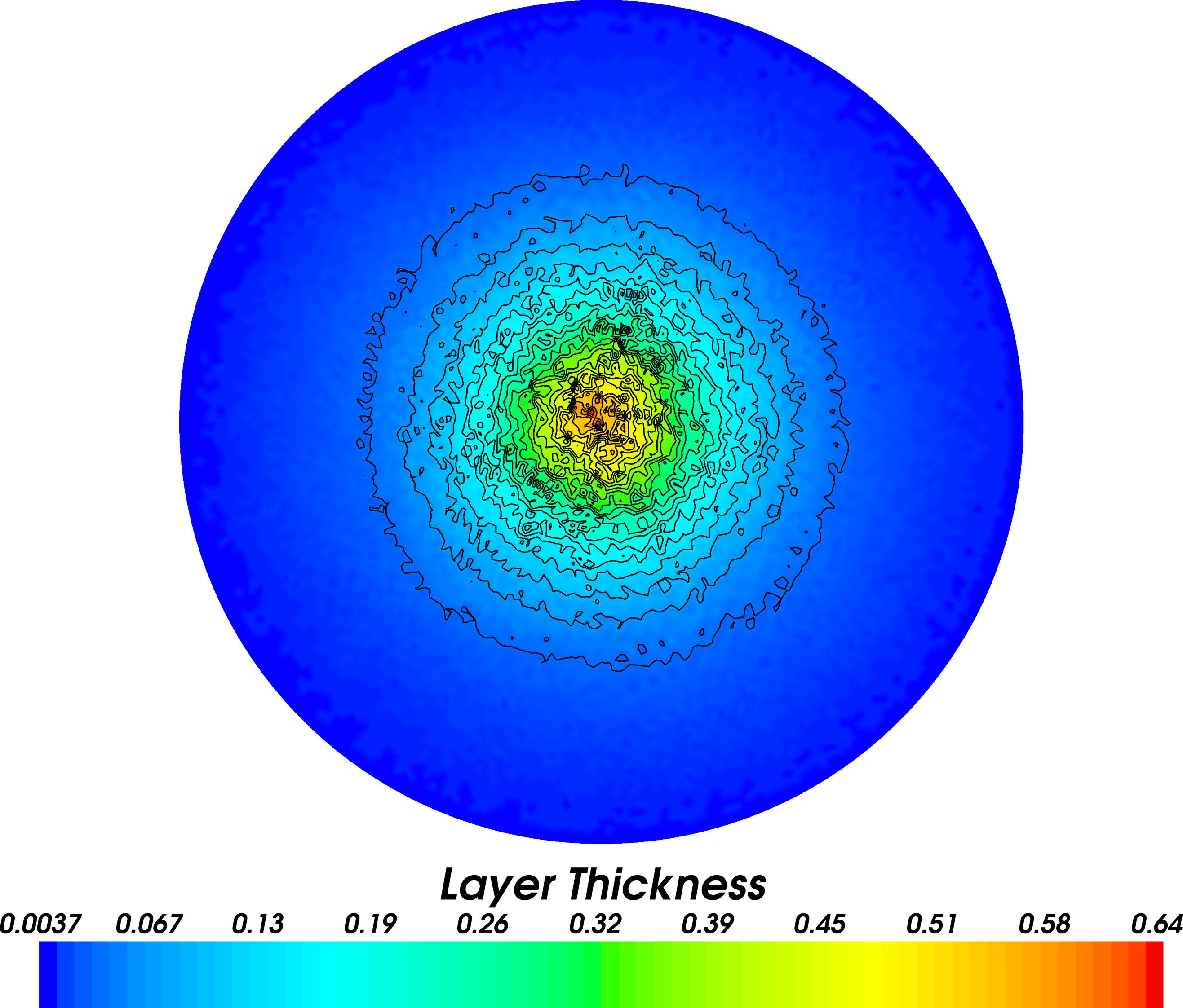
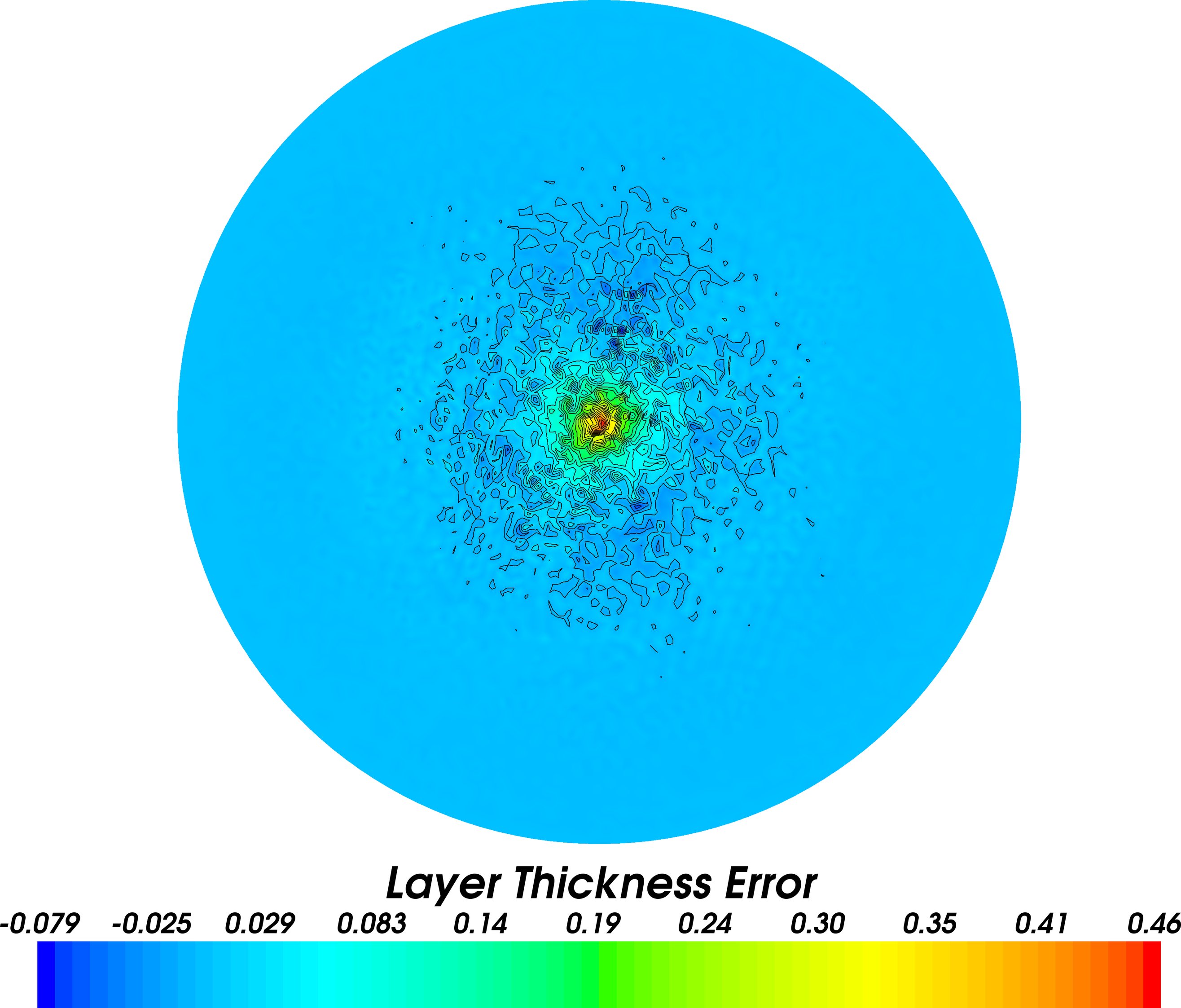
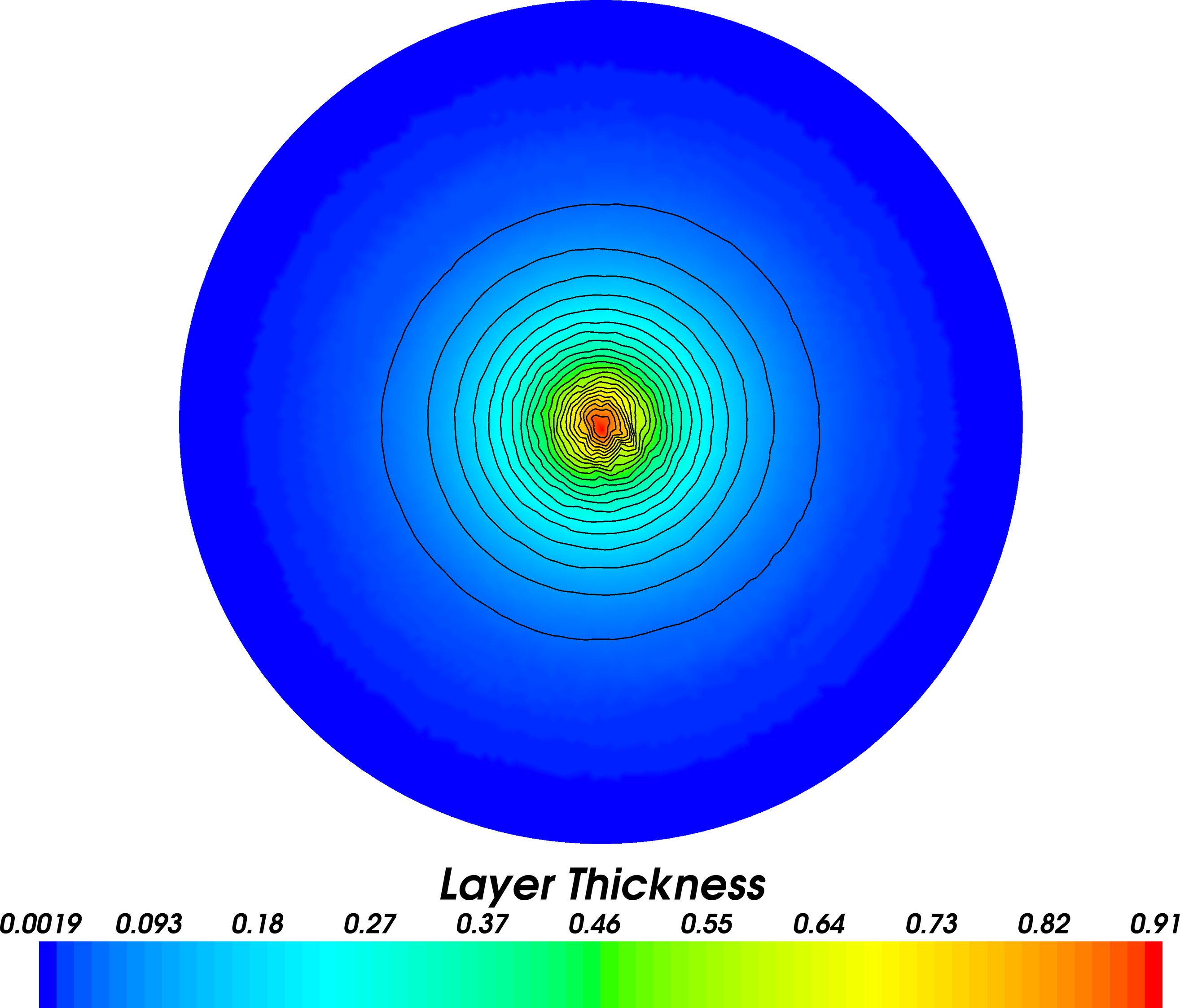
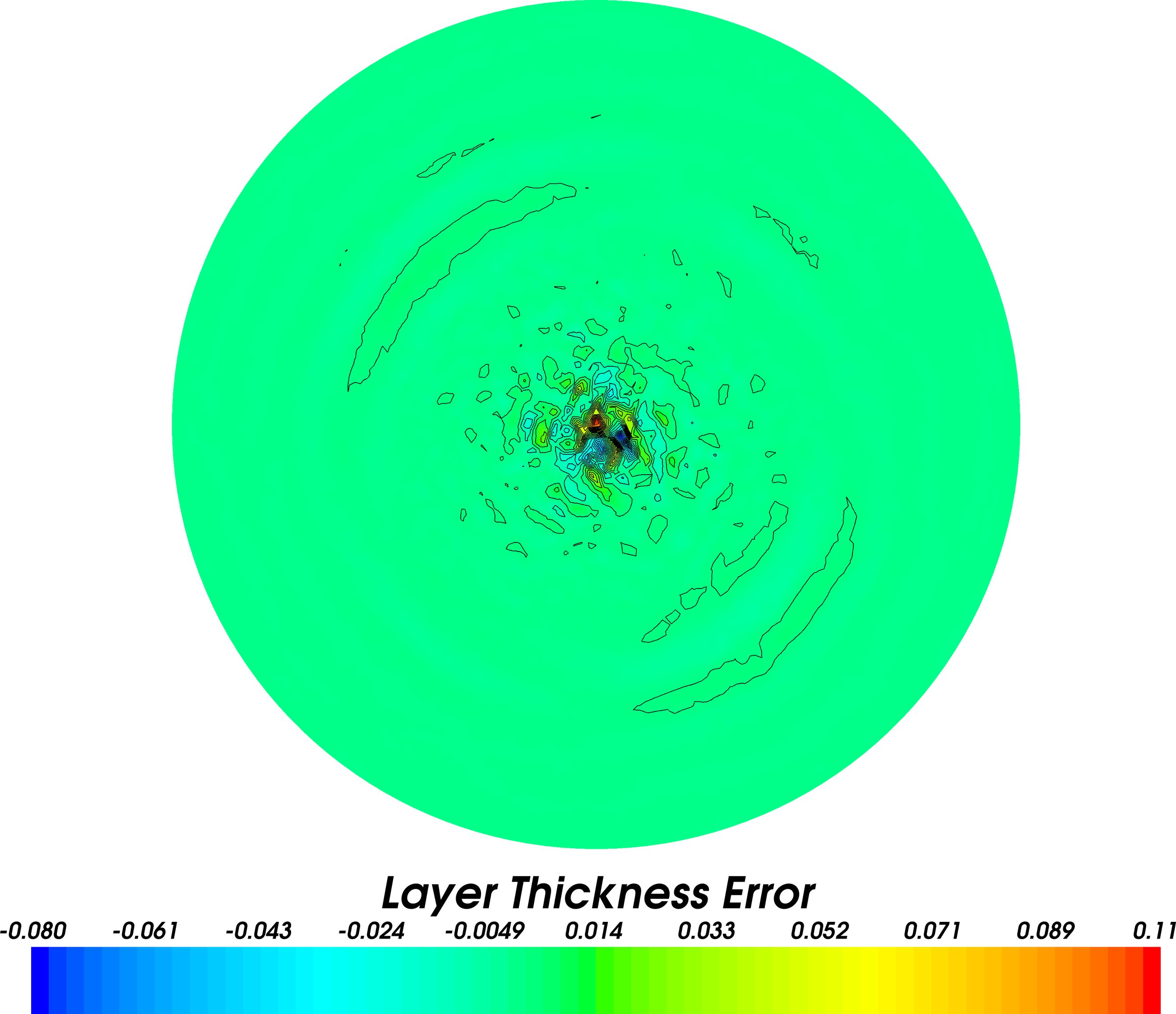
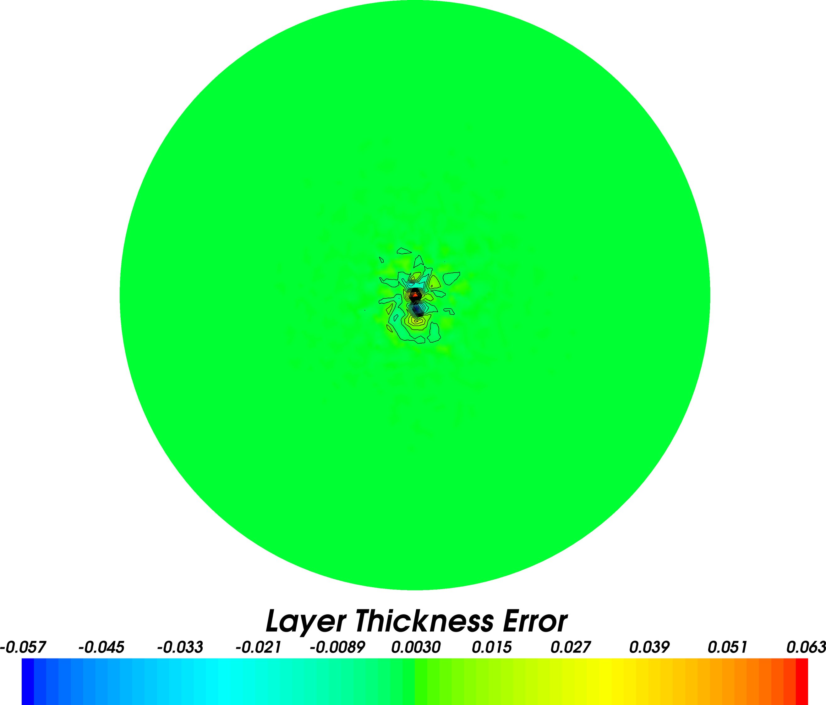
The final layer thickness and change in layer thickness from the initial condition are shown in figure 3, and the maximum change in layer thickness between each interpolation is shown in figure 4. Grandy interpolation is observed to inject imbalance everywhere after each interpolation, resulting in a severe degradation of the simulation fields after just a single interpolation. Galerkin projection is observed to inject imbalance towards the centre of the domain, near the layer thickness maximum. The resulting gravity waves propagate outwards polluting the global solution, and accumulate after every interpolation. The geostrophic balance preserving interpolant is exactly steady, to within machine precision, after every interpolation, with a change in layer thickness between interpolations of . The residual imbalance between interpolations is attributed to double precision round-off error.
After interpolations the layer thickness error is (of initial layer thickness norm) for Grandy interpolation, for Galerkin projection and for the geostrophic balance preserving interpolant. While Galerkin projection is optimal in the norm for each interpolation, the imbalance injection and resulting pollution of the solution by gravity waves leads to a reduced accuracy in the norm of the final model solution with respect to the geostrophic balance preserving interpolant.
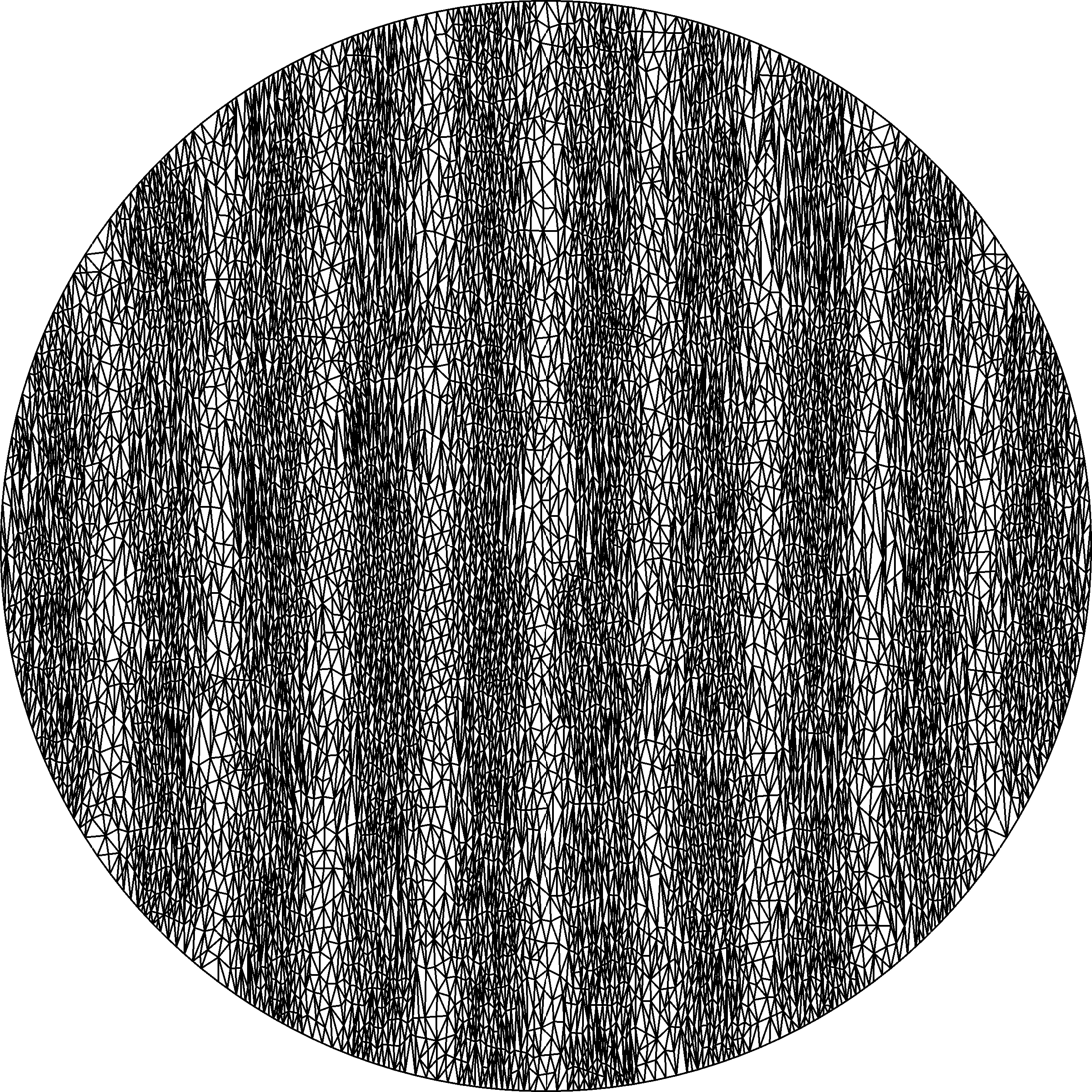
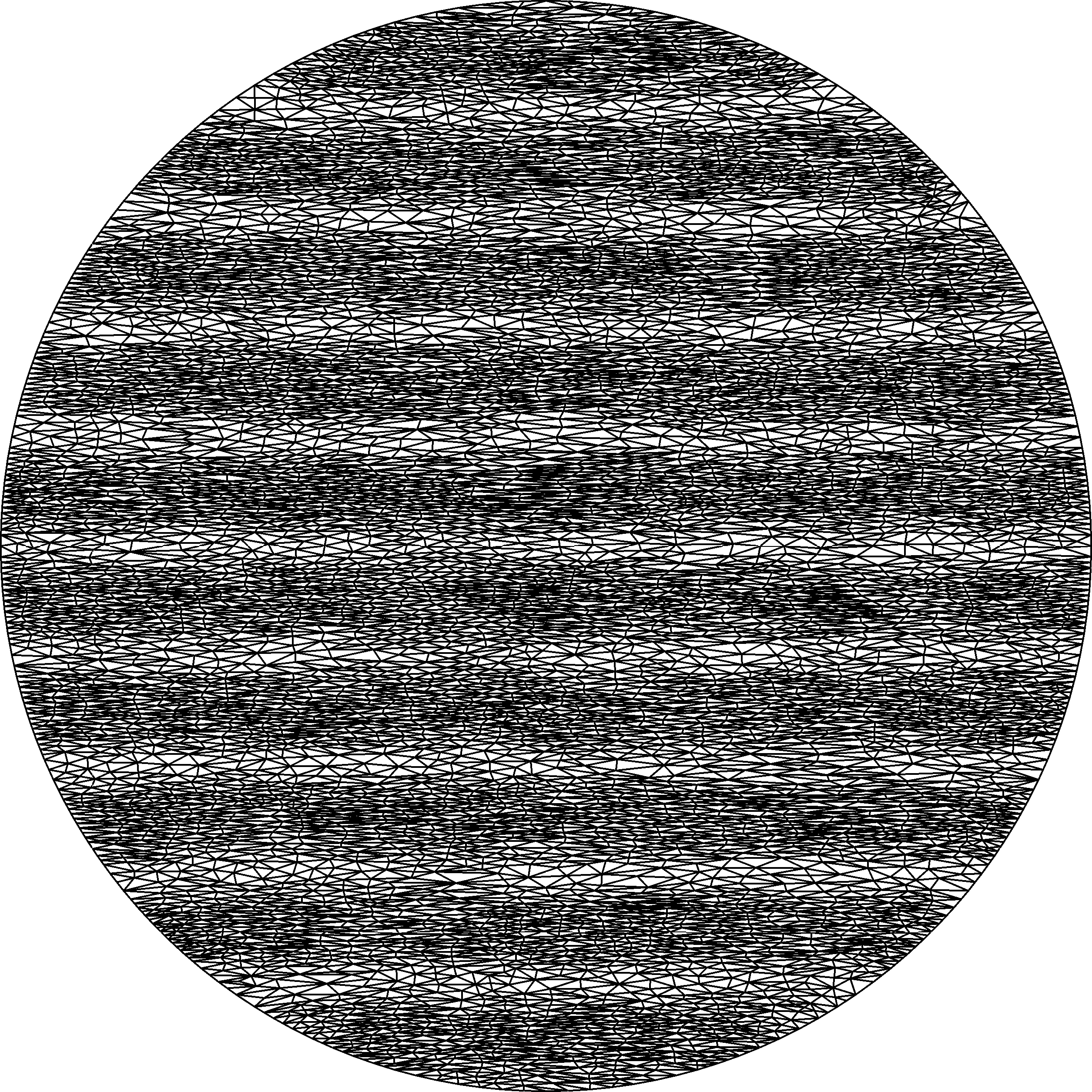
To further demonstrate geostrophic balance preservation the test was repeated on two anisotropic circular meshes C and D generated using Gmsh (Geuzaine and Remacle, 2009) and the ani2d mesh optimisation library (Vasilevskii and Lipnikov, 1999; Agouzal et al., 1999) with elements stretched in perpendicular directions as shown in figure 5. Meshes C and D have and nodes respectively, and a maximum element edge length ratio of . The velocity field was initialised to be in discrete geostrophic balance with this layer thickness as before, with interpolations backwards and forwards between the two meshes at timestep intervals for interpolations. Simulations were conducted using the geostrophic balance preserving interpolant, Galerkin projection, and Grandy interpolation, with the change in layer thickness between interpolations shown in figure 6. When applying the geostrophic balance preserving interpolation the maximum change between interpolations was as before.
 |
 |
| C | D |

Finally, the geostrophic balance preservation the test was repeated using the anisotropic meshes C and D in figure 5, with a layer thickness initialised to random values in the interior and a value of zero on the boundary. The velocity field was initialised to be in discrete geostrophic balance with this layer thickness. The model was integrated as before, with interpolations backwards and forwards between two two meshes at timestep intervals for interpolations, using the geostrophic balance preserving interpolant. The maximum change in layer thickness between interpolations was , and hence the solution was observed to be steady to within double precision round-off error.
3.2 Nearly balanced states
The Gaussian layer thickness profile in figure 2 had a perturbation applied of the form:
| (21) |
where is some point-wise random value in the range . This perturbation was smoothed using a Helmholtz smoother with a characteristic length scale of to produce the layer thickness perturbation shown in figure 7. The velocity field was initialised to be in discrete geostrophic balance with the unperturbed layer thickness, thereby generating a nearly balanced state.
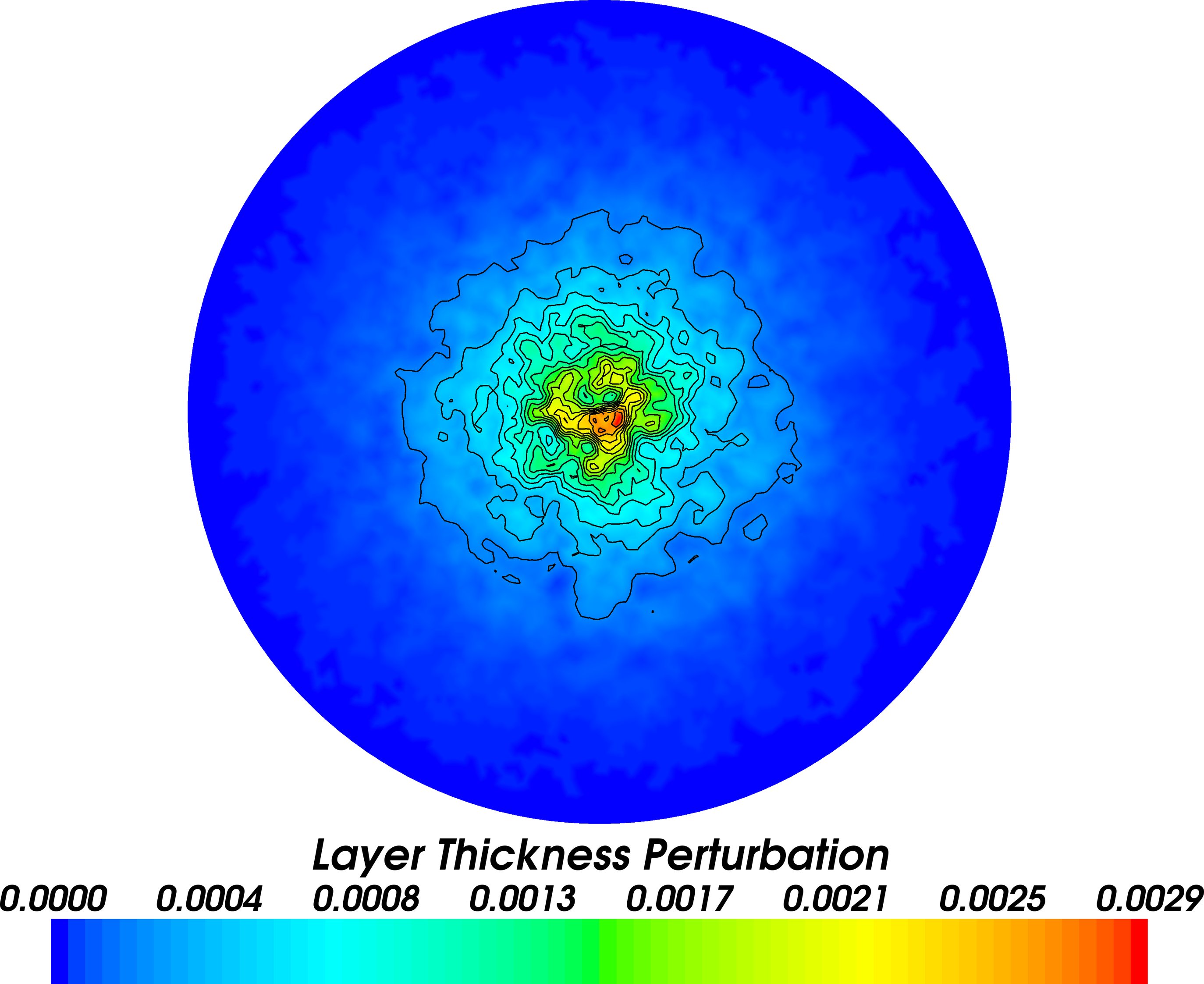
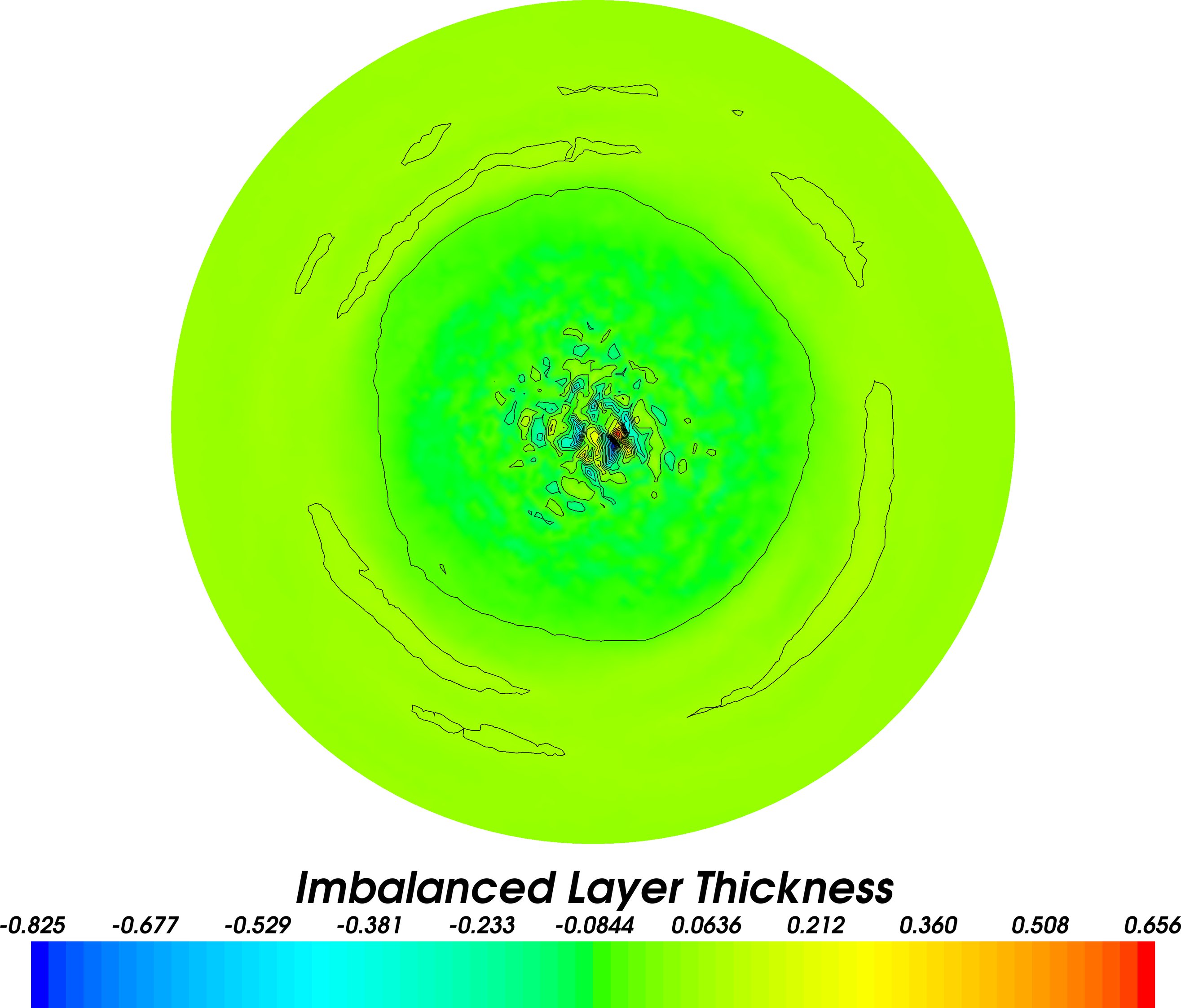
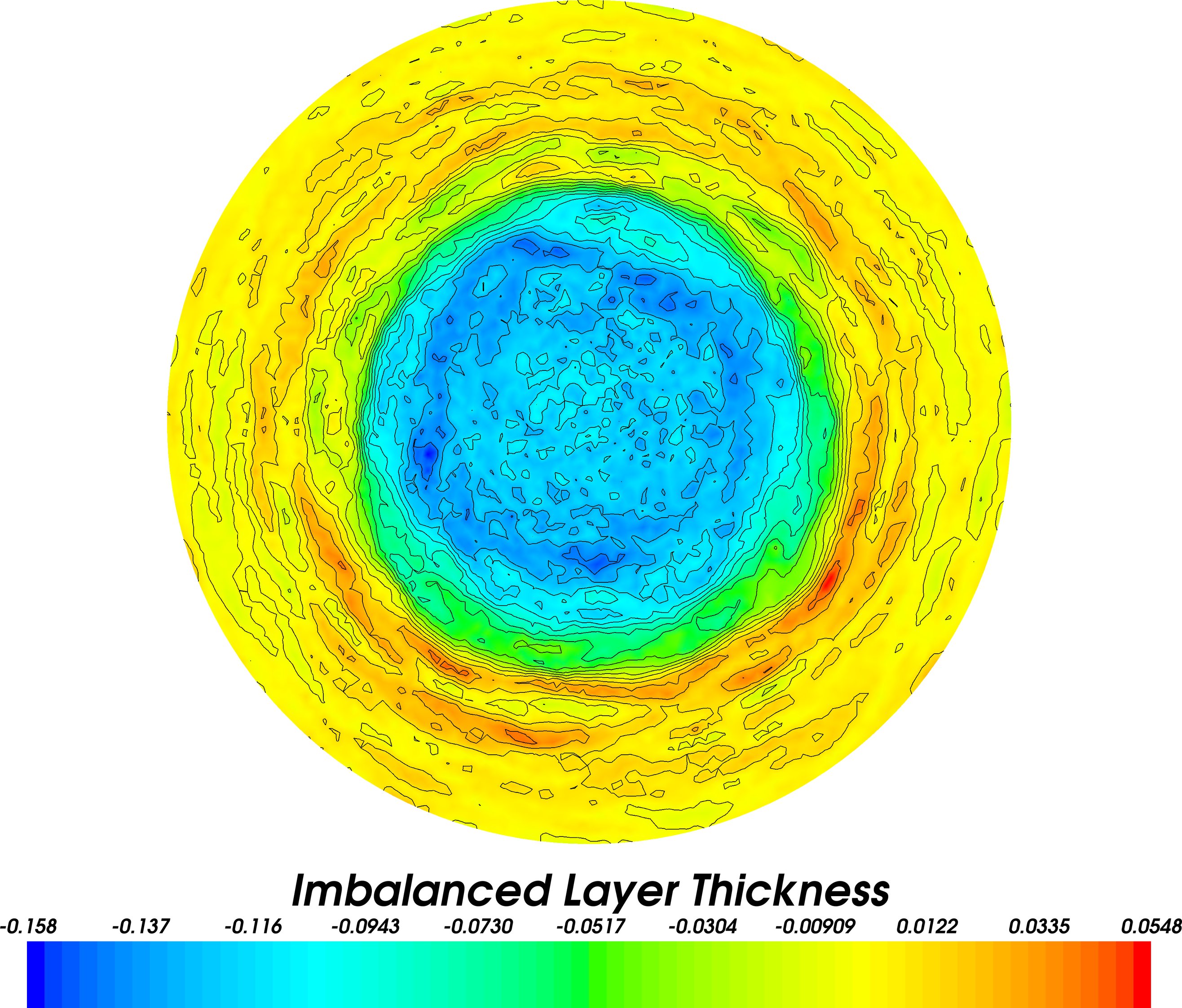
The system was integrated as before, with interpolations backwards and forwards between the pseudo-isotropic meshes A and B in figure 1 at timestep intervals. One can define an “imbalanced layer thickness”:
| (22) |
where is the scalar potential computed from the Helmholtz decomposition of the Coriolis acceleration. The final imbalanced layer thickness is shown for Galerkin projection and the geostrophic balance preserving interpolant in figure 8. When using Galerkin projection imbalance is observed to be injected near the layer thickness maximum. This additional imbalance dominates over the original layer thickness perturbation after interpolations. When using the geostrophic balance preserving interpolant propagation of the original layer thickness perturbation is observed, with no significant pollution introduced by the interpolation.
 |
 |
| A | B |
Defining a “balanced velocity” where:
| (23) |
and an “imbalanced velocity” :
| (24) |
allows one to compute an imbalanced kinetic energy:
| (25) |
The imbalanced kinetic energies when using Galerkin projection and the geostrophic balance preserving interpolant are shown in figure 9. When using Galerkin projection the imbalanced kinetic energy is observed to increase by up to a factor of in an interpolation, with the imbalanced kinetic energy peaking at times its initial value. When using the geostrophic balance preserving interpolant the imbalanced kinetic energy is observed to increase by at most a factor in an interpolation, and the imbalanced kinetic energy never exceeds its initial value.

3.3 Kelvin wave
The interpolant was tested for a Kelvin wave, configured as in in Ham et al. (2005); Cotter et al. (2009b) with an initial condition:
| (26a) | |||
| (26b) | |||
| (26c) |
for and in a circular domain of radius . The Kelvin wave is geostrophically balanced in the direction normal to the boundary and imbalanced in the tangential direction. The model was integrated with a timestep of for a total simulated time of , corresponding to the time taken for a single Kelvin wave to perform a circuit of the domain in the limit of large . Two meshes of quasi-uniform resolution with and nodes respectively were created using gmsh (Geuzaine and Remacle, 2009) and the ani2d mesh optimisation library (Vasilevskii and Lipnikov, 1999; Agouzal et al., 1999), and the solution interpolated backwards and forwards between these meshes at timestep intervals.
 |
 |
| A | B |
 |
 |
| C | D |
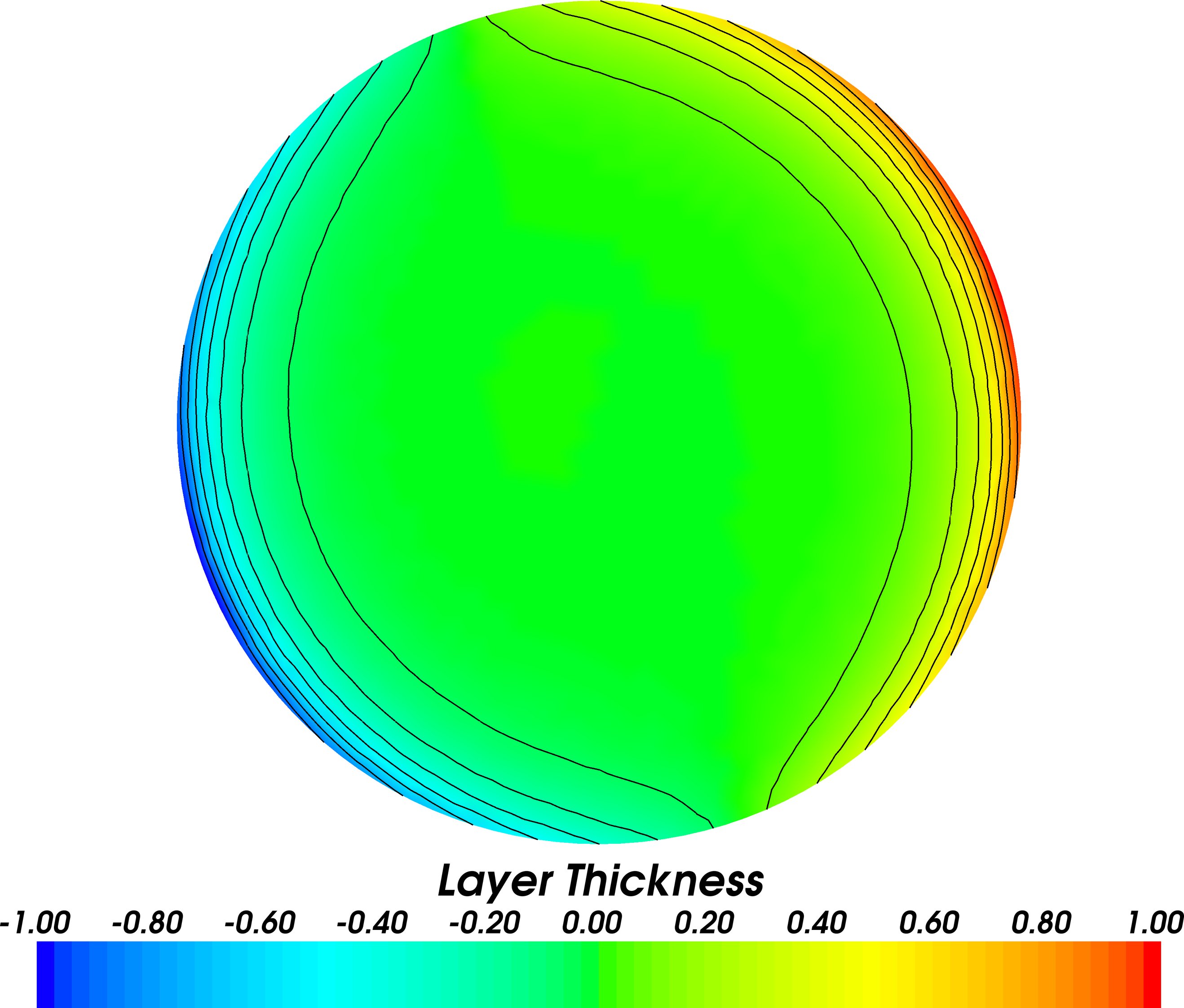
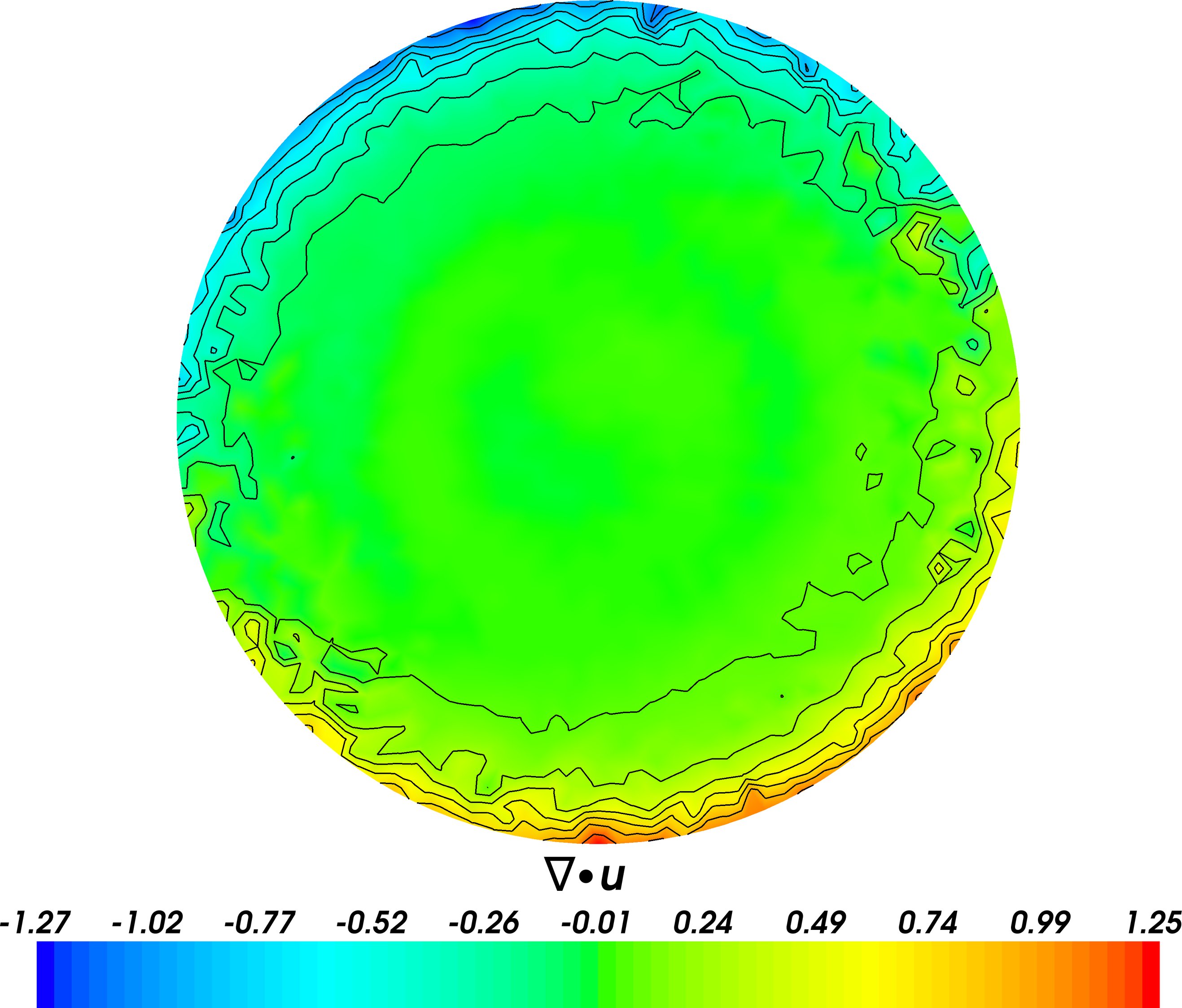
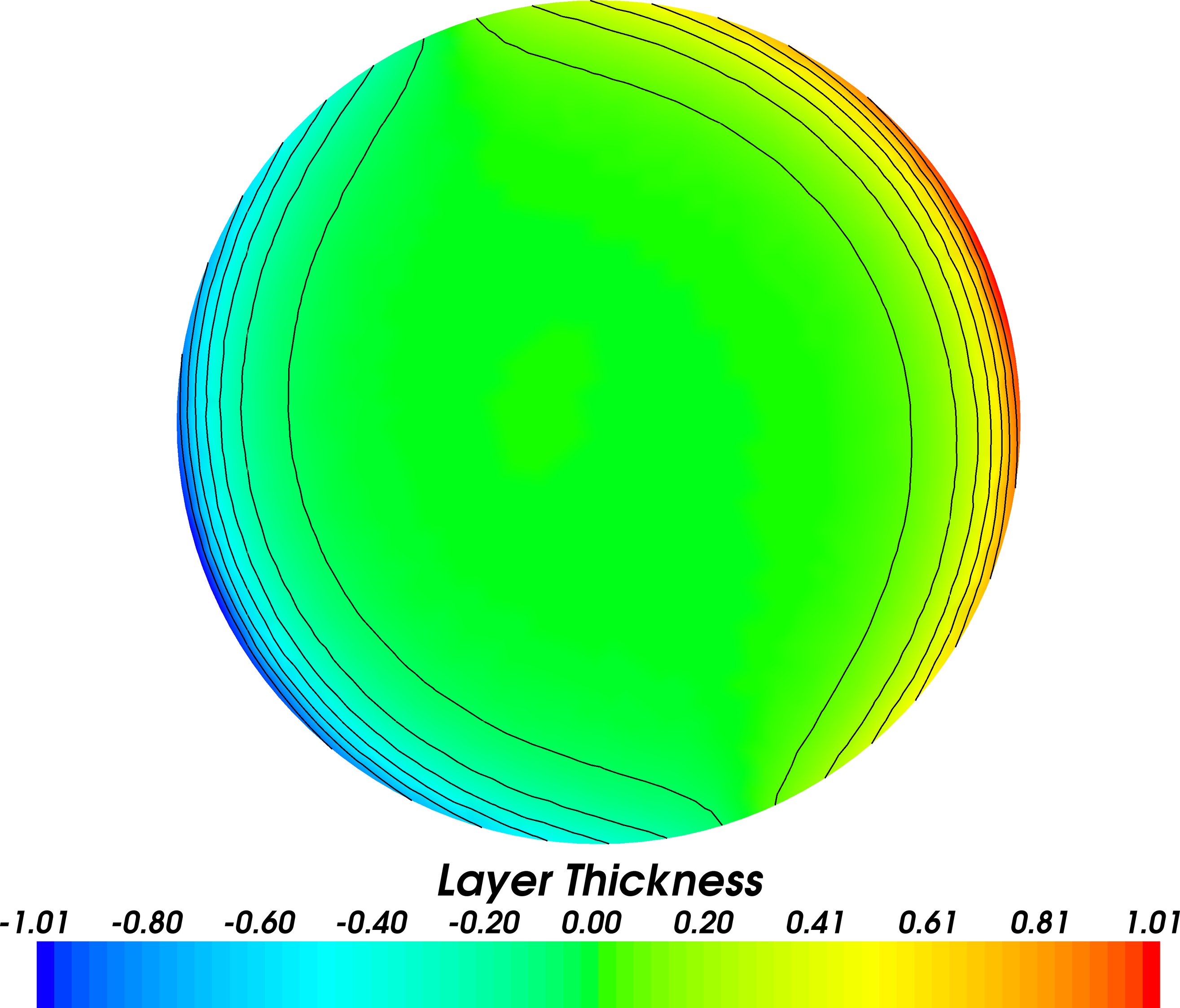
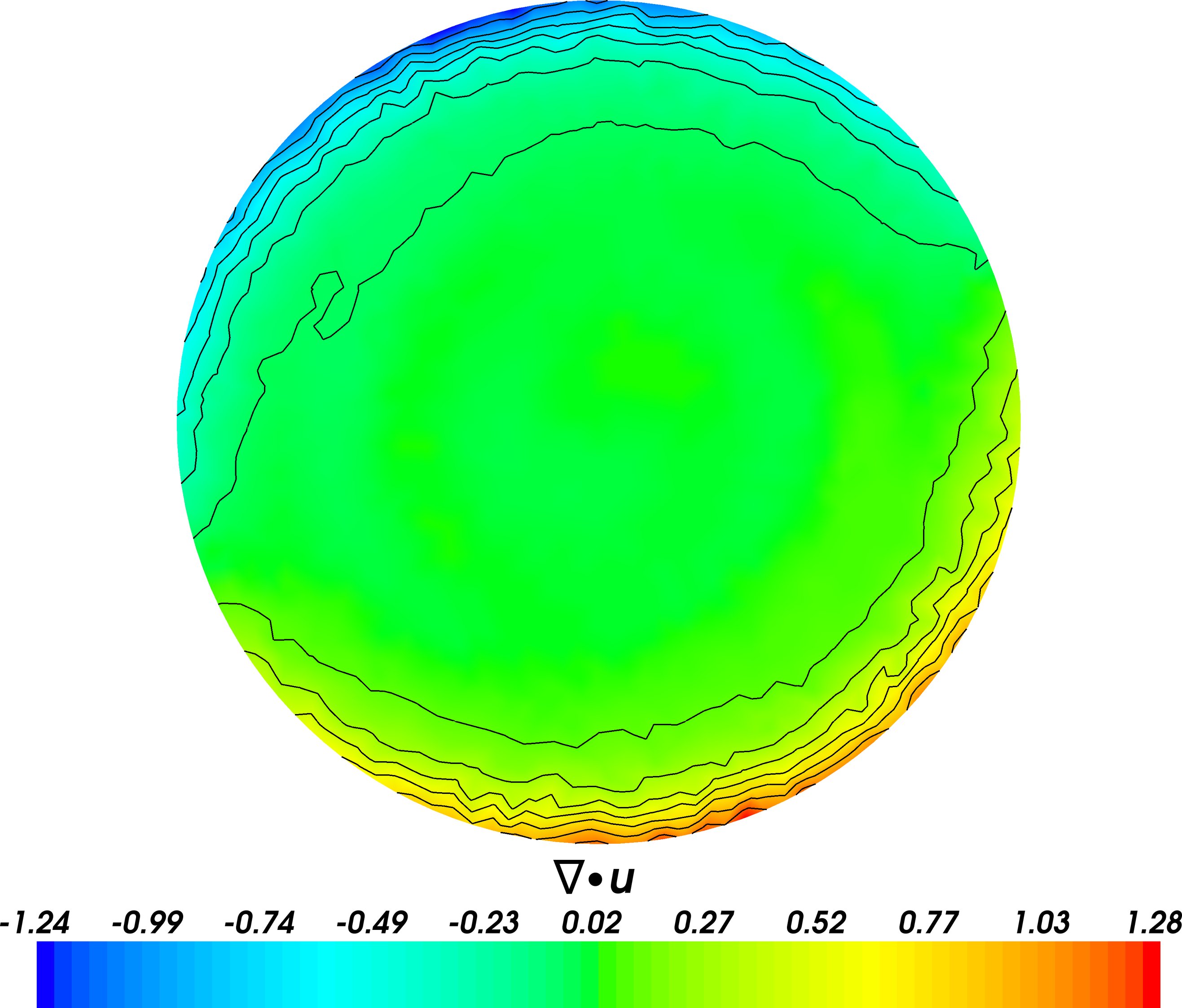
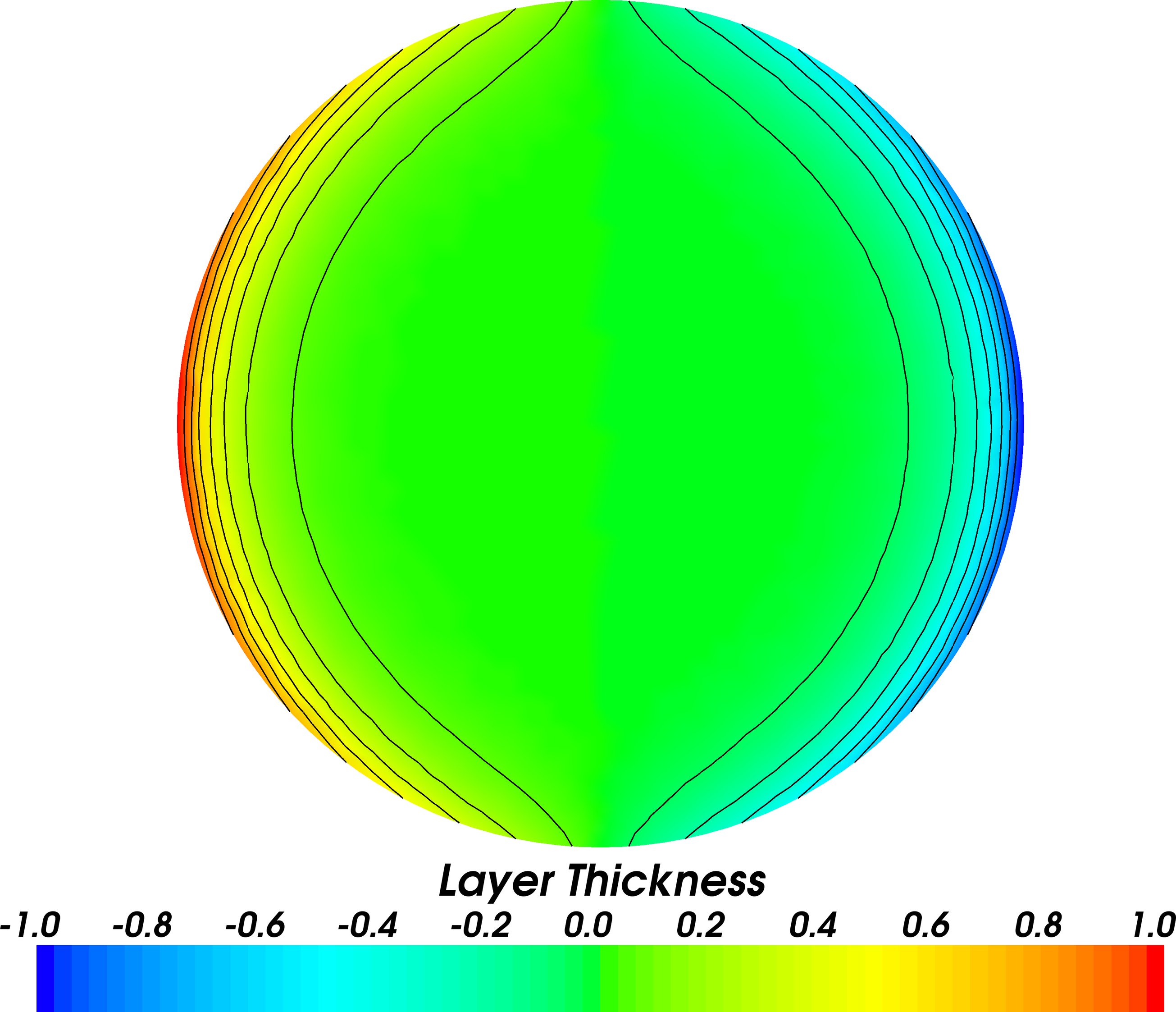
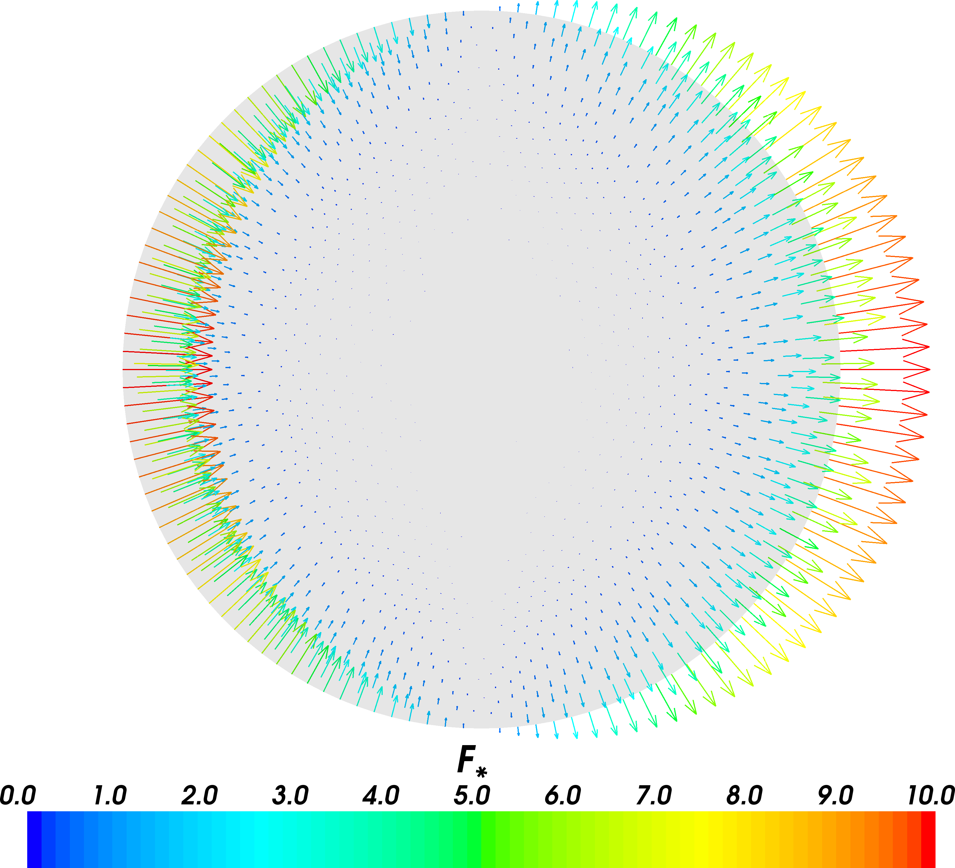
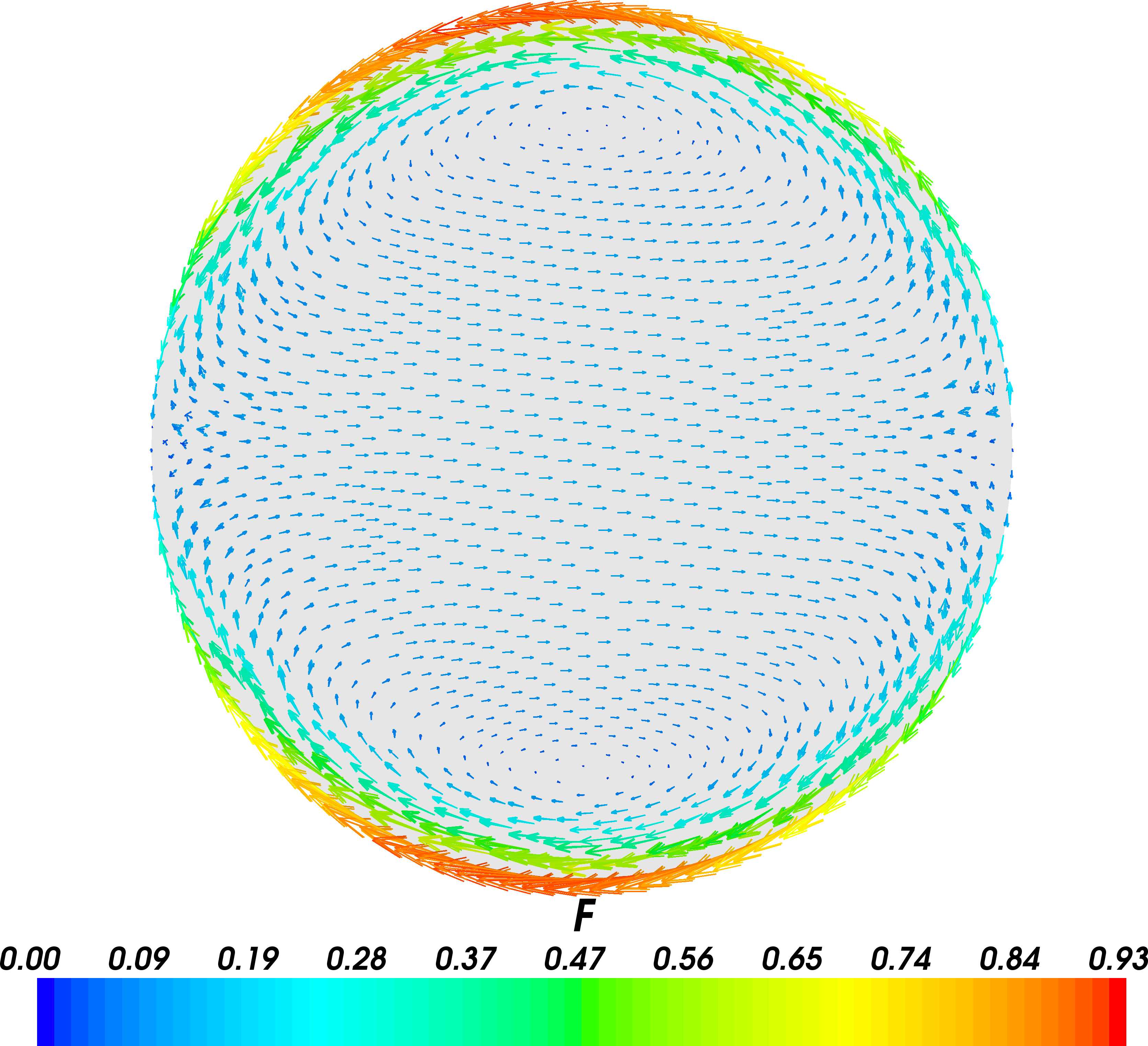
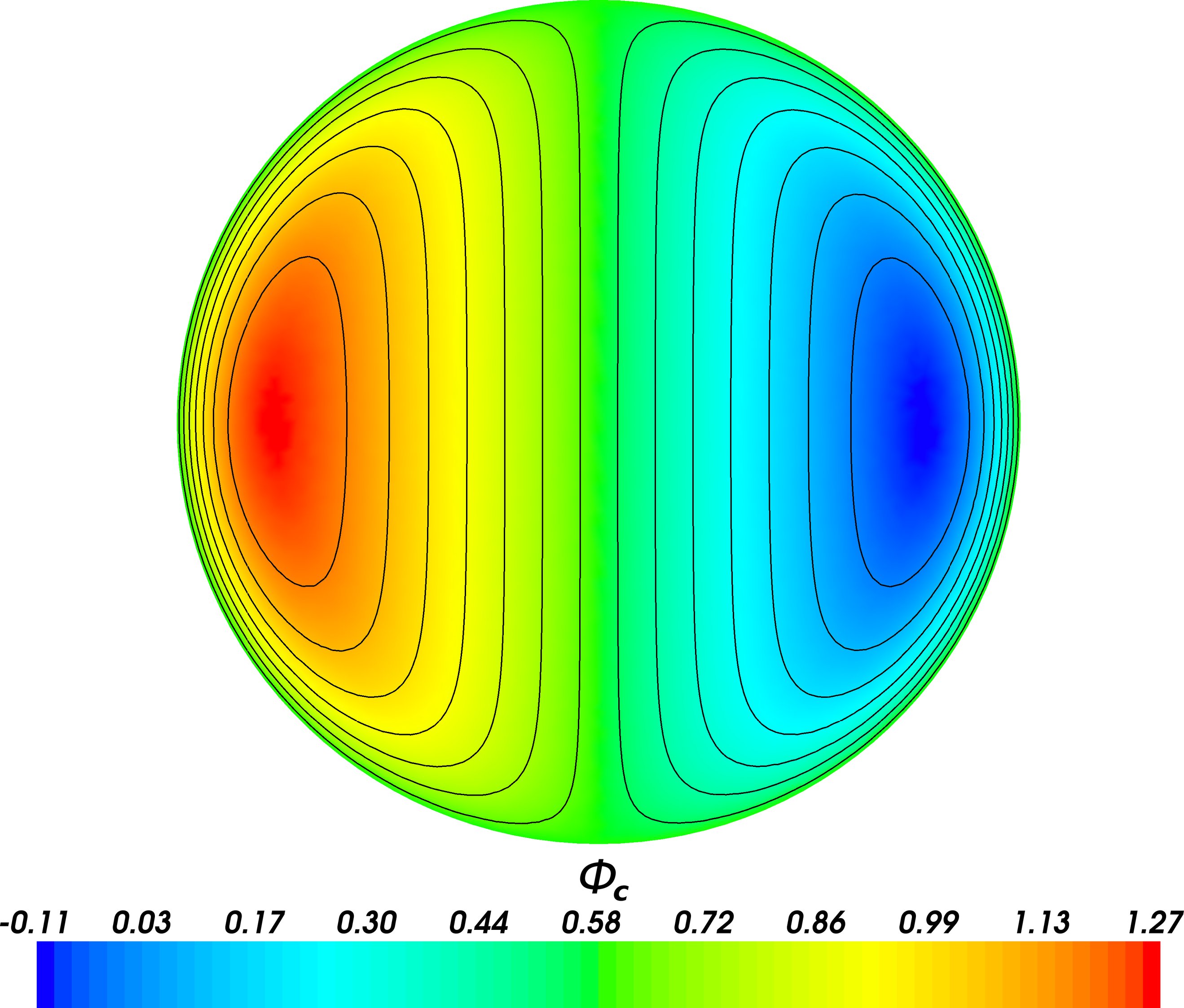
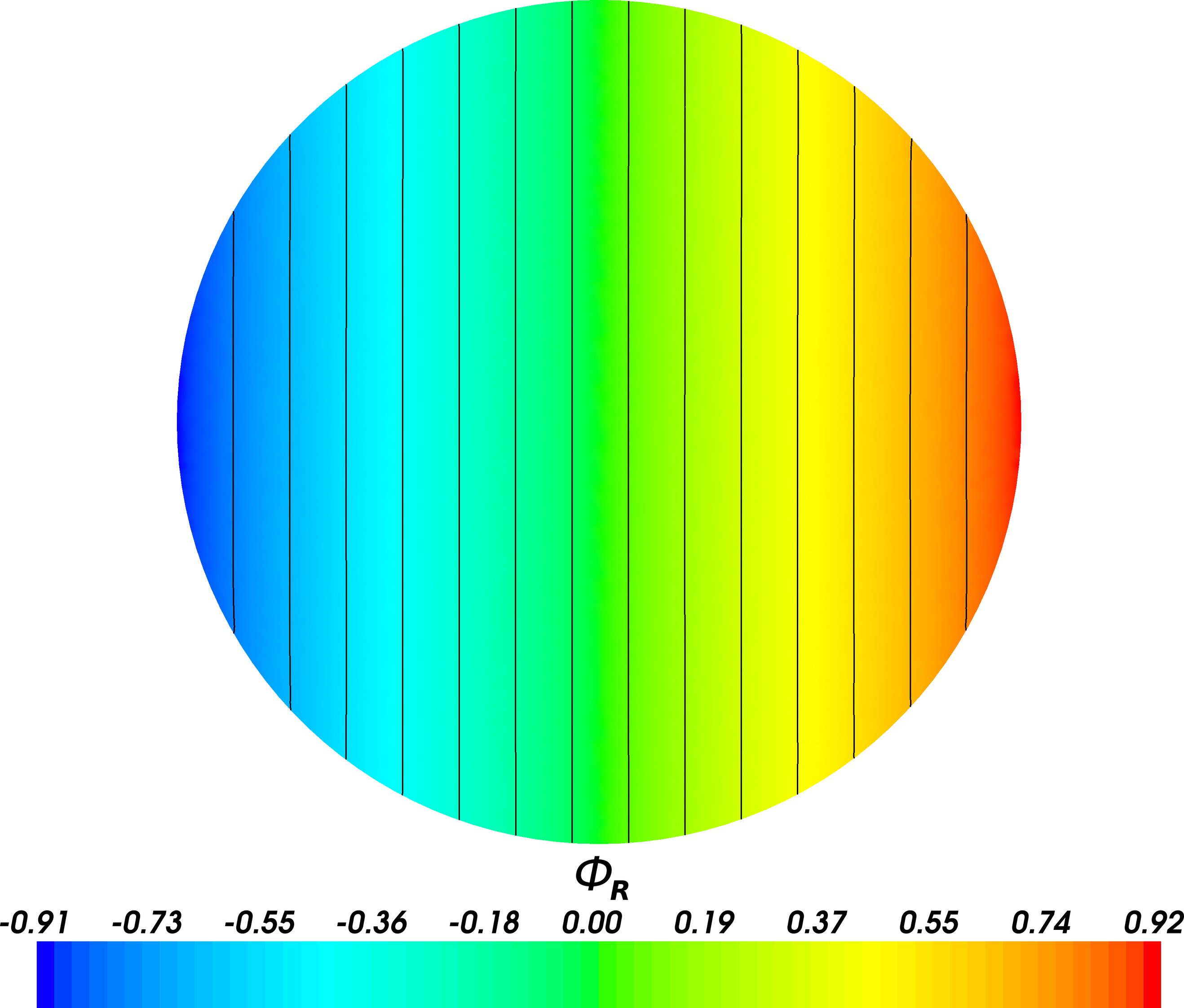
The initial layer thickness is shown in figure 10, and the Helmholtz decomposition of the initial Coriolis acceleration in figure 11. The final solutions when using Galerkin projection and the geostrophic balance preserving interpolant are shown in figure 12. Relatively little difference is observed in the final layer thickness field between these simulations. However, when using Galerkin projection, noise is observed in the velocity divergence field, originating at the boundary. This noise is significantly reduced when using the geostrophic balance preserving interpolant.
| A |
|
||
|---|---|---|---|
| B |
|
A discretisation of the linearised shallow-water equations conserves energy if the layer thickness gradient matrix is, after multiplication by some diagonal matrix, equal to the transpose of the velocity divergence matrix (Ham et al., 2007), and if the implicit mid-point rule is used for timestepping (Leimkuhler and Reich, 2004). Hence the spatial discretisation of the linearised shallow-water equations as presented here conserves the total energy. The kinetic, potential, and total energy of the system when using Galerkin projection, the geostrophic balance preserving interpolant, and when using a single fixed computational mesh, are shown in figure 13. The fixed mesh simulation is observed to conserve the total energy to within one part in , with the relatively high error attributed to the tolerances used for the linear solvers. The use of direct solvers, combined with more precision robust calculation of the energy diagnostics, is expected to decrease this error. When interpolating between meshes using Galerkin projection a systematic dissipation of both kinetic and potential energy is observed, leading to a decrease in the total system energy of after interpolations, at the end of the simulation. When using the geostrophic balance preserving interpolant a slight increase the potential energy is observed, leading to an increase in the total system energy of after interpolations. While the geostrophic balance preserving interpolant is not energy conserving, the change in system energy is, for this test, more than an order of magnitude smaller than that observed when applying Galerkin projection.
| A |
|
|
|---|---|---|
| B |
|
|
| C |
|
In further testing it was found that highly anisotropic elements intersecting the domain boundary led to very poor results when using the geostrophic balance preserving interpolant. This is likely due to significant interpolation errors in the projection of in this region, possibly as a result of the Dirichlet boundary condition for in the mesh-to-mesh Galerkin projection, which pollutes the interpolated Coriolis acceleration. This problem was solved by imposing constraints on the maximum element size for elements directly on the boundary.
3.4 Accuracy
Since the geostrophic balance preserving interpolant is composed of a Galerkin discretisation of the Helmholtz decomposition of the Coriolis acceleration followed by a donor-to-target Galerkin projection of the decomposition, when using the element pair the interpolant is expected to be second order accurate for velocity and third order accurate for layer thickness.
| Donor mesh resolution () | Target mesh resolution() |
|---|---|
A series of structured triangular mesh pairs for a 2D unit square and were generated with resolutions in the - and -directions as given in table 1. A layer thickness of the form:
| (27) |
and a velocity of the form:
| (28) |
were interpolated between the meshes in each pair using the geostrophic balance preserving interpolant. The first term in (28) corresponds to a flow that is, for , and , in geostrophic balance with the layer thickness (27). The remaining terms correspond to a flow that cannot be balanced by any layer thickness. In order to test for additional error introduced by the scalar potential and layer thickness decomposition, as per equation (17), tests were conducted for a doubly periodic and for a bounded domain. The errors , and , were computed explicitly via supermesh construction, as described in Farrell (2009). For comparison the fields were also projected using Galerkin projection, giving a measure of the quality of the geostrophic balance preserving interpolant relative to the projection that is optimal in the norm.
The resulting errors are shown for the doubly periodic domain in figure 14 and for the bounded domain in figure 15. The geostrophic balance preserving interpolant is observed to be second order accurate for velocity and third order accurate for layer thickness, as expected. For the doubly periodic domain the average norm error for the geostrophic balance preserving interpolant is observed to be times the optimal value for velocity, and (since no layer thickness decomposition is applied in this case) optimal for layer thickness. For the bounded domain the error in velocity is not significantly changed, and the error in layer thickness is increased to times the optimal value, indicating that the decomposition of the scalar potential and layer thickness introduces only a small additional error. For comparison, in Farrell (2009) collocation is found to give, for a field , an error that is times the optimal value for piecewise linear elements, and times the optimal value for piecewise quadratic elements.
 |
 |
 |
 |
4 Conclusions
We have presented an interpolation method that, when applied to the discretisation of the linearised shallow-water equations on an -plane, guarantees that steady and geostrophically balanced states on the donor mesh remain steady and geostrophically balanced after interpolation onto an arbitrary target mesh. We have stress tested this balance preserving property with highly anisotropic meshes and randomly initialised balanced states (constrained to satisfy appropriate boundary conditions). We have further demonstrated the utility of this interpolant for nearly balanced dynamics, and quantified its accuracy in the norm.
A shortcoming of this approach, at least in the form presented, is that is does not conserve energy. The Helmholtz decomposed interpolation of Coriolis acceleration does not conserve kinetic energy or potential energy. Despite this, the change in energy when using the geostrophic balance preserving interpolant was found to be more than an order of magnitude smaller than the energy dissipation when using Galerkin projection. In addition to this, the interpolant does not locally conserve potential vorticity. Geophysical flows are only in geostrophic balance to leading order, and a lack of potential vorticity conservation could, when non-linear advection is included in the fundamental equations, lead to higher order balance loss. Potential vorticity decompositions could be considered where such a conservation is desired (Staquet and Riley, 1989; Holopainen and Kaurola, 1991; McIntyre and Norton, 2000), although the benefit of such an approach, bearing in mind that discretisations of the non-linear shallow-water equations are not generally potential vorticity conserving, may be somewhat limited compared to the benefit of leading order balance preservation.
The method has a natural extension to Navier-Stokes. For incompressible Navier-Stokes any forcing that can be represented as the gradient of a scalar field must be filtered by the pressure gradient, and hence the interpolation of the Helmholtz decomposition of the Coriolis acceleration is a balance preserving interpolant. Future work will concentrate on the implementation of geostrophic balance preserving interpolation as part of the Imperial College Ocean Model - an unstructured dynamic mesh adaptive ocean model. In particular, we will investigate accurate preservation of geostrophic balance when using velocity-pressure element pairs that do not satisfy optimal balance properties, and the integration of methods used for accurate balance representation for such element pairs (Ford et al., 2004a, b; Piggott et al., 2006, 2008b; Fang et al., 2009) into a balance preserving interpolant. We will test how these can be used to propagate accurate balance representation through arbitrary mesh adapts for meshes that are fully unstructured in all three dimensions.
5 Acknowledgements
The authors wish to acknowledge support from the UK Natural Environment Research Council (grants NE/C52101X/1, NE/C51829X/1 and NE/H527032/1). The authors would also like to thank Prof. David P. Marshall and Dr. Hilary Weller for their comments and suggestions in preparing this article.
References
- Agouzal et al. (1999) Agouzal, A., Lipnikov, K., Vassilevski, Y., 1999. Adaptive generation of quasi-optimal tetrahedral meshes. East west journal of numerical mathematics 7 (4), 223–244.
- Balay et al. (2008) Balay, S., Buschelman, K., Eijkhout, V., Gropp, W. D., Kaushik, D., Knepley, M. G., McInnes, L. C., Smith, B. F., Zhang, H., 2008. PETSc Users Manual. Argonne National Laboratory, anl-95/11 - revision 3.0.0 Edition.
- Balay et al. (2009) Balay, S., Buschelman, K., Gropp, W. D., Kaushik, D., Knepley, M. G., McInnes, L. C., Smith, B. F., Zhang, H., 2009. PETSc Web page. http://www.mcs.anl.gov/petsc.
- Balay et al. (1997) Balay, S., Gropp, W. D., McInnes, L. C., Smith, B. F., 1997. Efficient management of parallelism in object oriented numerical software libraries. In: Arge, E., Bruaset, A. M., Langtangen, H. P. (Eds.), Modern Software Tools in Scientific Computing. Birkhäuser Press, pp. 163–202.
- Chorin (1967) Chorin, A. J., 1967. A numerical method for solving incompressible viscous flow problems. Journal of Computational Physics 2 (1), 12–26.
- Comblen et al. (2009) Comblen, R., Legrand, S., Deleersnijder, E., Legat, V., 2009. A finite element method for solving the shallow water equations on the sphere. Ocean Modelling 28 (1-3), 12–23.
- Cotter et al. (2009a) Cotter, C. J., Ham, D. A., Pain, C. C., 2009a. A mixed discontinuous/continuous finite element pair for shallow-water ocean modelling. Ocean Modelling 26 (1-2), 86–90.
- Cotter et al. (2009b) Cotter, C. J., Ham, D. A., Pain, C. C., Reich, S., 2009b. LBB stability of a mixed Galerkin finite element pair for fluid flow simulations. Journal of Computational Physics 228 (2), 336–348.
- Crank and Nicolson (1947) Crank, J., Nicolson, P., 1947. A practical method for numerical evaluation of solutions of partial differential equations of the heat-conduction type. Proc. Cambr. Phil. Soc 43, 50–67.
- Fang et al. (2009) Fang, F., Pain, C. C., Navon, I. M., Gorman, G. J., Piggott, M. D., Allison, P. A., Farrell, P. E., Goddard, A. J. H., 2009. A POD reduced order unstructured mesh ocean modelling method for moderate Reynolds number flows. Ocean Modelling 28 (1-3), 127–136.
- Farrell (2009) Farrell, P. E., 2009. Galerkin projection of discrete fields via supermesh construction. Ph.D. thesis, Imperial College London.
- Farrell et al. (2009) Farrell, P. E., Piggott, M. D., Pain, C. C., Gorman, G. J., Wilson, C. R., 2009. Conservative interpolation between unstructured meshes via supermesh construction. Computer Methods in Applied Mechanics and Engineering 198 (33-36), 2632–2642.
- Ford et al. (2004a) Ford, R., Pain, C. C., Piggott, M. D., Goddard, A. J. H., de Oliveira, C. R. E., Umpleby, A. P., 2004a. A nonhydrostatic finite-element model for three-dimensional stratified oceanic flows. Part I: Model Formulation. Monthly Weather Review 132 (12), 2816–2831.
- Ford et al. (2004b) Ford, R., Pain, C. C., Piggott, M. D., Goddard, A. J. H., de Oliveira, C. R. E., Umpleby, A. P., 2004b. A nonhydrostatic finite-element model for three-dimensional stratified oceanic flows. Part II: Model validation. Monthly weather review 132 (12), 2832–2844.
- Geuzaine and Remacle (2009) Geuzaine, C., Remacle, J. F., 2009. Gmsh: a three-dimensional finite element mesh generator with built-in pre-and post-processing facilities. International Journal for Numerical Methods in Engineering 79 (11), 1309–1331.
- Grandy (1999) Grandy, J., 1999. Conservative remapping and region overlays by intersecting arbitrary polyhedra. Journal of Computational Physics 148 (2), 433–466.
- Gresho (1990) Gresho, P. M., 1990. On the theory of semi-implicit projection methods for viscous incompressible flow and its implementation via a finite element method that also introduces a nearly consistent mass matrix. Part 1: Theory. International Journal for Numerical Methods in Fluids 11 (5), 587–620.
- Ham et al. (2007) Ham, D. A., Kramer, S. C., Stelling, G. S., Pietrzak, J., 2007. The symmetry and stability of unstructured mesh C-grid shallow water models under the influence of Coriolis. Ocean Modelling 16 (1-2), 47–60.
- Ham et al. (2005) Ham, D. A., Pietrzak, J., Stelling, G. S., 2005. A scalable unstructured grid 3-dimensional finite volume model for the shallow water equations. Ocean Modelling 10 (1-2), 153–169.
- Holopainen and Kaurola (1991) Holopainen, E., Kaurola, J., 1991. Decomposing the atmospheric flow using potential vorticity framework. Journal of the Atmospheric Sciences 48, 2614–2625.
- Ladyzhenskaya (1969) Ladyzhenskaya, O. A., 1969. The mathematical theory of viscous incompressible flow. New York, 1O.
- Le Roux et al. (1998) Le Roux, D. Y., Staniforth, A., Lin, C. A., 1998. Finite elements for shallow-water equation ocean models. Monthly Weather Review 126 (7), 1931–1951.
- Leimkuhler and Reich (2004) Leimkuhler, B., Reich, S., 2004. Simulating Hamiltonian dynamics. Cambridge Univ Pr.
- McIntyre and Norton (2000) McIntyre, M. E., Norton, W. A., 2000. Potential vorticity inversion on a hemisphere. Journal of the Atmospheric Sciences 57 (9), 1214–1235.
- Munday et al. (2010) Munday, D. R., Marshall, D. P., Piggott, M. D., 2010. Idealised flow past an island in a dynamically adaptive finite element model. Ocean Dynamics, in press.
- Pain et al. (2005) Pain, C. C., Piggott, M. D., Goddard, A. J. H., Fang, F., Gorman, G. J., Marshall, D. P., Eaton, M. D., Power, P. W., de Oliveira, C. R. E., 2005. Three-dimensional unstructured mesh ocean modelling. Ocean Modelling 10 (1-2), 5–33.
- Pain et al. (2001) Pain, C. C., Umpleby, A. P., De Oliveira, C. R. E., Goddard, A. J. H., 2001. Tetrahedral mesh optimisation and adaptivity for steady-state and transient finite element calculations. Computer Methods in Applied Mechanics and Engineering 190 (29-30), 3771–3796.
- Piggott et al. (2008a) Piggott, M. D., Gorman, G. J., Pain, C. C., Allison, P. A., Candy, A. S., Martin, B. T., Wells, M. R., 2008a. A new computational framework for multi-scale ocean modelling based on adapting unstructured meshes. International Journal for Numerical Methods in Fluids 56 (8), 1003.
- Piggott et al. (2008b) Piggott, M. D., Pain, C. C., Gorman, G. J., Marshall, D. P., Killworth, P. D., 2008b. Unstructured adaptive meshes for ocean modeling.
- Piggott et al. (2006) Piggott, M. D., Pain, C. C., Gorman, G. J., Power, P. W., Goddard, A. J. H., 2006. h, r, and hr adaptivity with applications in numerical ocean modelling. Ocean Modelling 10 (1-2), 95–113.
- St-Cyr et al. (2008) St-Cyr, A., Jablonowski, C., Dennis, J. M., Tufo, H. M., Thomas, S. J., 2008. A comparison of two shallow water models with non-conforming adaptive grids. Monthly Weather Review 136 (6), 1898.
- Staquet and Riley (1989) Staquet, C., Riley, J. J., 1989. On the velocity field associated with potential vorticity. Dynamics of Atmospheres and Oceans 14, 93–123.
- Temam (1968) Temam, R., 1968. Une méthode d’approximation de la solution des équations de Navier-Stokes. Bull. Soc. Math. France 98, 115–152.
- Vasilevskii and Lipnikov (1999) Vasilevskii, Y. V., Lipnikov, K. N., 1999. An adaptive algorithm for quasioptimal mesh generation. Computational mathematics and mathematical physics 39 (9), 1468–1486.
- Weyl (1940) Weyl, H., 1940. The method of orthogonal projection in potential theory. Duke Mathematical Journal 7 (1), 411–444.
