Lateral spatial switching of excitons using vertical electric fields in semiconductor quantum rings
Abstract
We study the response of exciton complexes in semiconductor quantum rings to vertical electric fields, using path integral quantum Monte Carlo simulations. The interaction of a vertical applied field and the piezoelectric fields of the ring with strongly-correlated excitonic complexes switches excitons between two different lateral locations within the ring . This control should be observable through polarizability and dipole measurements, and, for biexcitons, an energy shift beyond the normal Stark shift.
Semiconductor nanostructures allow for the tailoring of their optical and electronic properties by manipulation of their size, shape, and composition profile. A widely-studied class of nanostructures are InGaAs/GaAs self-assembled quantum dots, which have found a wide range of applications from single photon sources to quantum information processing.Imamog-lu et al. (1999); Yuan et al. (2002) Beyond such passive tailoring of properties during growth, active control of nanostructure properties through external fields, especially switching behavior, is highly desirable.
Under proper annealing conditions, quantum dots undergo a significant migration of In outwards from the center of the dot, forming a ring-shaped nanostructure with a crater at the center Lorke et al. (2001); Offermans et al. (2005); Granados et al. (2005); Baranwal et al. (2009); Mlakar et al. (2008); Granados and García (2003); García et al. (1997); Pettersson et al. (2000). Previous theoretical and experimental work has show that quantum rings behave differently from their quantum dot cousins Warburton et al. (2002); Alén et al. (2007); Galbraith et al. (2002), with distinct but equally rich electronic and optical properties. These unique properties stem from the GaAs barrier material at the ring’s core, which significantly modifies the confinement potential and—at the heart of the phenomena we report here—creates a strain profile that is unique to rings. An important difference that has been previously identified is the distribution of the piezoelectric field, which is seen to play a much more important role in rings than in dots Barker et al. (2004). Unlike in dots, where the majority of the piezoelectric potential sits outside the electrically active part of the structure—leaving the electron and hole ground states mostly unaffected—the strained central core of GaAs material in a quantum ring induces large piezoelectric potentials within the confining structure itself. These piezoelectric fields break the rotational symmetry of the ring, vertically separate the electron and hole, and induce localization.
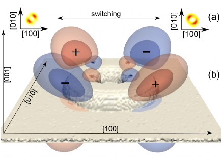
We theoretically investigate quantum rings and predict that the interplay of piezoelectric and strain effects with electron-hole Coulomb interactions, will enable a lateral switching of the probability distribution of the exciton when a vertical electric field is applied. As illustrated in Fig. 1(a), the exciton distribution in the ring can rotate 90∘. Such two-state behavior resembles a pair of electrons in quantum dot cellular automata (QCA) cell Snider et al. (1999), and we address connections to QCA later in the discussion. Further we show that this switching should be experimentally observable by a change in the lateral polarizability.
Method—Based on the XTEM image of a quantum ring observed by Lin et al Lin et al. (2009), we construct a model ring that is 6 nm at its maximum height with an inner radius 5 nm and outer radius 20 nm, made from a 50 (In,Ga)As random alloy, sitting upon a thin 30 In wetting layer. We carried all simulations at a temperature of 10 K.
We use a two band effective mass model Hamiltonian with conduction and valence bands derived from the strain profile of an atomistic model of the nanostructure using the valence force field method Harowitz et al. (2005). To simplify our analysis and presentation, we created eight atomistic models of the same ring, with different realizations of the random alloy, and present the average of these eight rings, with ideal C2v symmetry imposed. The piezoelectric potential is computed from the strain field and are included to second order following the work of Bester et al Bester et al. (2006); *Bester_PRB_2006 and others Schliwa et al. (2007); Yu-Min et al. (2009). Path integral quantum Monte Carlo Ceperley (1995); Harowitz et al. (2005); Shumway is then used to solve the system for exctions and biexcitons. This method properly treats quantum correlation—which is crucial for proper description of excitons in rings—at realistic finite temperatures with arbitrary three-dimensional confining potentials. We obtain polarizabilites from path integral quantum Monte Carlo using linear response theory.
Piezoelectric fields and switching behavior—As can be seen in Fig. 1, the ring is sectioned into quarters by the piezoelectric field, which has C2v symmetry. Fig. 1(b) clearly shows the top eight lobes in the piezoelectric potential, with an equal number of lobes (with opposite sign) directly beneath the ring, two of which can be seen at the front edge. The larger lobes, on the outer edge of the ring, resemble the piezoelectric potential found in a quantum dot; the majority of the field sits outside of the structure. The extra, smaller lobes within the GaAs core, which sit directly above and below the quantum ring and penetrate the structure, are not found in dots. These extra lobes have a significant effect on the quantum ring’s electronic structure.
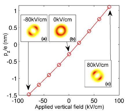
An electric field in the vertical growth direction ([001]), perpendicular to the plane of the ring, polarizes the exciton in the growth direction, Fig. 2. The vertically polarized excitons are attracted to the smaller piezoelectric potential lobes in the GaAs core (Fig. 1) that align with the induced excitonic dipole. Changing the direction of the vertical electric field will cause either the [110] or [10] direction to be lower in energy, while the other diagonal higher in energy. This switching of the lateral localization with a changing of the vertical electric field direction can be seen in Fig. 2(a) and (c), which shows how the mean electron probability distribution aligns along either [110] or [10] depending on the sign of the field.
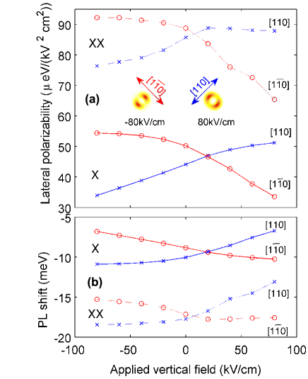
Observable effect on the lateral polarizability—This switching should be experimentally visible by examining the in plane polarizability of the exciton and biexciton in the ring. As the vertical electric field is applied and the exciton localizes into the appropriate nodes as in Fig. 2 (a) and Fig. 2 (c), there is a significant change in the polarizability of the complex. For example, a positive field causes the exciton to localize in the [10] direction, resulting in an increase in the lateral polarizability tangential to the direction of confinement—the [110] direction—as seen in Fig. 3. A negative field causes a larger polarizability in the [10] direction.
From our electron-hole correlation data (not shown) we can see that throughout the switching of the applied vertical electric field the exciton stays bound, an increase in the field merely increases the separation between the electron and hole, increasing the vertical dipole as in Fig. 2 as such the dipole can also be used as a experimental observable in conjunction with the polarizability e.g. it’s effect on altering the recombination lifetime Wimmer et al. (2006). Due to the piezoelectric potential inverting its sign every 90∘, the applied fields will not only align the exciton along different diagonals with a switch in field direction but also be accompanied by a change in the direction of the dipole moment in the z-direction.
The larger polarizability in [10] than in [110] (as in Fig. 3) and the negative permanent dipole that exists in the quantum ring at zero field (as in Fig. 2) show that the exciton tends to align preferentially in the [110] direction at zero field, with the holes towards the bottom of the ring. As has been previously shown Warburton et al. (2002), the holes tend to stay away from areas of high biaxial strain, here located near the top of the quantum ring, whilst the electrons do not suffer such an issue and are more free to spread out. This explains the permanent dipole in the quantum ring. The preferential alignment and thus polarizability difference at zero field can again be put down to the piezoelectric effect, with the exciton aligning with the nodes which match the holes affinity towards the bottom of the ring, and so further lower the complex’s energy.
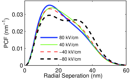
Structure of the biexciton—For a biexciton complex, there is a subtle change from the case of the always bound exciton. The larger confinement for holes towards the bottom of the ring will force the two holes together for a negative vertical electric field. As the holes are forced closer together with a stronger field, this higher energy cost can counter the biexciton binding energy and cause it to begin splitting into two excitons on either side of the ring. A positive electric field where the holes are towards the top of the ring, will tend to split the biexciton more slowly as the extra confinement caused by the ring structure itself is now missing. This is illustrated in Fig. 4, which shows the hole-hole separation at 40 kV/cm are similar, however when increased to 80 kV/cm the negative field begins to split the biexciton, which can be seen as the emergence of a second peak at approximately 20nm, while the positive field continues to reduce the separation and no second peak is visible. We suspect the difference in behavior between the positive and negative fields on the quantum ring in the case of the biexciton accounts for the more unusual polarizability seen for the biexciton seen in Fig. 3.
Relation to QCA—While the geometry of the exciton and biexciton localization and switching behavior are reminiscent of electrons in four-dot QCA cells, the excitons are neutral objects. Interactions between quantum rings, which are necessary for QCA circuits,Snider et al. (1999) are dipole-dipole, hence very weak and only effective at low temperature, perhaps in quantum information processing Biolatti et al. (2000).
Summary—In conclusion, we have shown that it is possible to gain an extra degree of freedom via the lateral control of an exciton complex in a quantum ring nanostructure by exploiting its unusual inbuilt piezoelectric field, and through the application of an external vertically applied electric field. We also suggest how this may be experimentally detected through polarizability and dipole measurements.
P.G.M and I.G. acknowledge funding from EPSRC, Carnegie Trust, J.S from the NSF DMR 02-39819.
References
- Imamog-lu et al. (1999) A. Imamog-lu, D. D. Awschalom, G. Burkard, D. P. DiVincenzo, D. Loss, M. Sherwin, and A. Small, Phys. Rev. Lett., 83, 4204 (1999).
- Yuan et al. (2002) Z. Yuan, B. E. Kardynal, R. M. Stevenson, A. J. Shields, C. J. Lobo, K. Cooper, N. S. Beattie, D. A. Ritchie, and M. Pepper, Science, 295, 102 (2002).
- Lorke et al. (2001) A. Lorke, R. J. Luyken, J. M. Garcia, and P. M. Petroff, Jpn. J. Appl. Phys., 40, 1857 (2001).
- Offermans et al. (2005) P. Offermans, P. Koenraad, J. Wolter, D. Granados, J. García, V. Fomin, V. Gladilin, and J. Devreese, Appl. Phys. Lett., 87, 131902 (2005).
- Granados et al. (2005) D. Granados, J. M. Garcia, T. Ben, and S. I. Molina, Appl. Phys. Lett., 86, 071918 (2005).
- Baranwal et al. (2009) V. Baranwal, G. Biasiol, S. Heun, A. Locatelli, T. O. Mentes, M. N. n. Orti, and L. Sorba, Phys. Rev. B, 80, 155328 (2009).
- Mlakar et al. (2008) T. Mlakar, G. Biasiol, S. Heun, L. Sorba, T. Vijaykumar, G. U. Kulkarni, V. Spreafico, and S. Prato, Appl. Phys. Lett., 92, 192105 (2008).
- Granados and García (2003) D. Granados and J. M. García, Appl. Phys. Lett., 82, 2401 (2003).
- García et al. (1997) J. M. García, G. Medeiros-Ribeiro, K. Schmidt, T. Ngo, J. L. Feng, A. Lorke, J. Kotthaus, and P. M. Petroff, Appl. Phys. Lett., 71, 2014 (1997).
- Pettersson et al. (2000) H. Pettersson, R. Warburton, A. Lorke, K. Karrai, J. Kotthaus, J. Garcia, and P. Petroff, Physica E, 6, 510 (2000).
- Warburton et al. (2002) R. J. Warburton, C. Schulhauser, D. Haft, C. Schäflein, K. Karrai, J. M. Garcia, W. Schoenfeld, and P. M. Petroff, Phys. Rev. B, 65, 113303 (2002).
- Alén et al. (2007) B. Alén, J. Bosch, D. Granados, J. Martínez-Pastor, J. García, and L. González, Phys. Rev. B, 75, 45319 (2007).
- Galbraith et al. (2002) I. Galbraith, F. Braid, and R. Warburton, Phys. Stat. Sol. (a), 190, 781 (2002).
- Barker et al. (2004) J. A. Barker, R. J. Warburton, and E. P. O’Reilly, Phys. Rev. B, 69, 035327 (2004).
- Snider et al. (1999) G. L. Snider, A. O. Orlov, I. Amlani, G. H. Bernstein, C. S. Lent, J. L. Merz, and W. Porad, Jpn. J. Appl. Phys., 38 (1999).
- Lin et al. (2009) C. H. Lin, H. S. Lin, C. C. Huang, S. K. Su, S. D. Lin, K. W. Sun, C. P. Lee, Y. K. Liu, M. D. Yang, and J. L. Shen, Appl. Phys. Lett., 94, 183101 (2009).
- Harowitz et al. (2005) M. Harowitz, D. Shin, and J. Shumway, J. Low Temp. Phys., 140, 211 (2005).
- Bester et al. (2006) G. Bester, X. Wu, D. Vanderbilt, and A. Zunger, Phys. Rev. Lett., 96, 187602 (2006a).
- Bester et al. (2006) G. Bester, A. Zunger, X. Wu, and D. Vanderbilt, Phys. Rev. B, 74, 081305 (2006b).
- Schliwa et al. (2007) A. Schliwa, M. Winkelnkemper, and D. Bimberg, Phys. Rev. B, 76, 205324 (2007).
- Yu-Min et al. (2009) L. Yu-Min, Y. Zhong-Yuan, J. Bo-Yong, X. Zi-Huan, Y. Wen-Jie, C. Zhi-Hui, L. Peng-Fei, and H. Li-Hong, Chin. Phys. B, 18, 4667 (2009).
- Ceperley (1995) D. M. Ceperley, Rev. Mod. Phys, 67, 279 (1995).
- (23) J. Shumway, “pi-qmc,” http://code.google.com/p/pi-qmc/.
- Wimmer et al. (2006) M. Wimmer, S. V. Nair, and J. Shumway, Phys. Rev. B, 73, 165305 (2006).
- Biolatti et al. (2000) E. Biolatti, R. C. Iotti, P. Zanardi, and F. Rossi, Phys. Rev. Lett., 85, 5647 (2000).