Correlation between stick-slip frictional sliding and charge transfer
Abstract
A decade ago, Budakian and Putterman (Phys. Rev. Lett., 85, 1000 (2000)) ascribed friction to the formation of bonds arising from contact charging when a gold tip of a surface force apparatus was dragged on polymethylmethacrylate surface. We propose a stick-slip model that captures the observed correlation between stick-slip events and charge transfer, and the lack of dependence of the scale factor connecting the force jumps and charge transfer on normal load. Here, stick-slip dynamics arises as a competition between the visco-elastic and plastic deformation time scales and that due to the pull speed with contact charging playing a minor role. Our model provides an alternate basis for explaining most experimental results without ascribing friction to contact charging.
pacs:
81.40.Pq, 46.55.+d, 05.10.-aI Introduction
Despite its long history, several aspects of friction remain ill understood even today. This can be partly attributed to the fact that mechanisms contributing to friction are scale dependent and those operating at lower scales contribute to friction at higher scales. The situation is further complicated as several other factors such as the possible presence of interfacial layer between the contacting surfaces, plastic deformation of the contacting asperities, contact electrification etc., are also known to contribute. Recent advances in friction force microscope and surface force apparatus (SFA) have provided useful tools to understand friction at these scales Gao04 ; Hamola90 ; Carpick96 ; Berman98 . This coupled with large scale molecular dynamics (MD) simulations Mo09 ; Luan06 have provided a better understanding of the mechanisms that contribute to friction at nanometer contacts and their relevance to macroscopic friction. Experimental studies show that Amontons’ law (the linear relationship between frictional force and load) holds in a number of situations (from nanometer to macroscopic dimensions) when adhesion is small or the surface is rough (either dynamically induced or otherwise Gao04 ; Hamola90 ; Carpick96 ; Berman98 ). However, smooth adhesive contacts follow Johnson-Kendal-Roberts (JKR) theory JKR71 ; Johnson85 . Recent MD simulations support experimental findings to a large extent Mo09 ; Sz08 .
In contrast, the dynamical aspects of intermittent frictional sliding are less studied Hamola90 ; Carpick96 ; Heslot94 . Efforts to understand stick-slip dynamics have established that plastic deformation of the contacting interfacial material is responsible for slip Heslot94 ; Baumberger99 ; EB96 ; Sz08 ; Landman92 ; Landman96 ; SJS96 ; Chen04 . A decade ago, Budakian and Putterman BP00 , proposed a new point of view that friction is due to the formation of bonds arising from contact charging. This claim however is at variance with earlier studies that show negligible contribution from contact charging to friction Roberts77 ; Hgraf72 ; Akande05 ; Lee94 for charge density charges/ reported in Ref. BP00 .
The authors demonstrate a correlation between stick-slip events and charge transfer when the gold tip (radius ) of the cantilever of a SFA was dragged with a velocity of a few on polymethylmethacrylate (PMMA) surface BP00 . Typical measured charge density charges/. The magnitude of the slip events is proportional to the ensuing charge transfer to the PMMA surface. Interestingly, the total force and the total charge deposited over a scan length collapses onto a single curve when an appropriate choice of a scale factor is made. The value of eV is close to the energy window for transfer of charge between the surface states of PMMA and metallic Fermi level Lee94 . Further, the authors find to be nearly constant in the range of normal loads from to . Based on these observations, they ascribe frictional force to the formation of bonds due to contact charging at the interface. Snapping of bonds leads to slip. To the best of our knowledge, there is no model that explains these intriguing results. Our purpose is to construct a model that captures the major results BP00 . Our model provides an alternate explanation for the observed correlation and the lack of dependence of the scale factor on normal load. The threshold for slip is determined by plastic deformation of the interface material Heslot94 ; EB96 while contact charge plays a minor role.
II Background
II.1 Motivation and approach
A notable feature of stick-slip systems is that the stick phase lasts much longer than the slip phase. Then, it is intuitively clear that charge builds up during the stick phase and charge transfer to the PMMA substrate occurs during the slip phase. In view of this, our idea is to first construct a stick-slip model based on contact mechanics of single asperity contact and other relevant physical processes, and couple it to charging and charge transfer equations. Then, as the contribution from contact charging to friction is small Roberts77 ; Hgraf72 ; Akande05 ; Lowell80 ; Lee94 , we expect the correlation between slip events and charge transfer should follow. Indeed, if one is interested in bringing-out the correlation between stick-slip events and charge transfer only, a ’toy’ model for stick-slip that includes velocity weakening law as an input coupled to charging and charge transfer equations is adequate. Such a model has been shown to reproduce the required correlation Note0 . However, as our interest is to recover most experimental features, we attempt to include all relevant features of friction and contact mechanics.
Sliding friction is well recognized to be a complex phenomenon with multiple possible scenarios depending on the precise experimental conditions Gao04 ; Sz08 . The nature of the results depend on variety of factors such as the size of the tip radius (typically radius for AFM and radius for SFA), the load levels, the nature of contacting materials, the nature of the initial and final microstructures of the tip and the substrate (smooth or rough), the magnitude of adhesion or the presence of intervening layer etcGao04 ; Sz08 ; Hamola90 ; Carpick96 ; Berman98 . For example, very different conditions such as low adhesion and rough or damaged surfaces can lead to similar friction-load relationship Gao04 ; Hamola90 ; Carpick96 ; Berman98 . For our case, such detailed information on the precise experimental conditions on the microstructure of the gold tip or the nature of surface of the PMMA substrate before and after the scan, is not provided in Ref. BP00 . In view of this and in view of the fact that any model building effort to understand the stick-slip dynamics requires quantitative information on the contact area, we use contact mechanics as the basis of our model. Moreover, the JKR theory has been validated in a number of SFA like situations.
II.2 Single asperity contact, visco-elasticity, plasticity and contact charging
By necessity our approach to modeling will be dynamical. The idea is to construct a stick-slip model that builds on known results for elastic deformation of the contacting surfaces by adding contributions from visco-elastic and plastic deformations of the contacting surfaces. Contact mechanics offers a mathematical basis for quantitative description of contact radius and penetration depth. The theory deals with smooth nonadhesive and adhesive contacts is designed as an equilibrium theory. Yet, experiments show that it is applicable to a number of sliding conditions as wellGao04 ; Sz08 ; Hamola90 ; CGMS09 . Non-adhesive contact was addressed by Hertz later extended to adhesive contacts by Johnson-Kendal-Roberts and later by Maugis JKR71 ; Johnson85 ; Maugis92 . In these theories, the area of the contact is a sub-linear function of the normal load JKR71 ; Maugis92 . As the Hertz contact area differs less than from the JKR contact area (for normal loads and tip radius used in BP00 ), we use the Hertz’s contact area given by . Here, is the contact radius, is the penetration depth, and is the effective elastic constant (of the contacting materials). The value of is for load . Thus, the estimated value of stress is that is higher than the compressive yield stress of PMMA Stach97 , but smaller than the yield stress of gold . (See Table 1.) Thus, the plastic deformation is largely confined to the weaker PMMA material. This view is supported by MD simulations as well Sz08 ; Landman92 ; Landman96 ; Chen04 ; SJS96 .
Quite early, it was shown that accelerated creep of the asperities leads to slip Heslot94 . Later studies show that stick-slip instabilities arise from two competing mechanisms, namely, ’geometric aging’ of the contacting asperities and ’rejuvenation by motion due to plastic deformation’ Baumberger99 . Models for stick-slip instability have been proposed using these ideas Heslot94 ; Baumberger99 . Indeed, aging kinetics of contacting asperities has been used to derive a ’N’-shaped velocity dependent friction coefficientEB96 , a generic feature of most stick-slip systems Heslot94 ; Baumberger99 ; GA07 . Dislocation assisted model for frictional sliding has also been suggested HK99 . Further, MD simulations also show plastic deformation of the contacting interfacial material and possible transfer of material between the contacting surfaces Sz08 ; Landman92 ; Landman96 ; Chen04 ; SJS96 . Thus, we consider plastic deformation of the interfacial layer is responsible for slip.
Even though the subject of contact electrification is rather old, the mechanisms underlying the charge transfer between a metal and polymer are still debated Lowell80 ; Lee94 . However, the fact that contact electrification contributes to adhesion is well recognized. A number of early studies suggest small contribution to adhesion Roberts77 ; Hgraf72 ; Akande05 ; Lowell80 ; Lee94 for the charge levels reported in Ref. BP00 . An estimate of the adhesive force from contact charging can be obtained by considering a charged double layer formed at the interface. Noting that contact charging can occur only at the area of contact given by , the attractive force is given by , where is the charge density and is the vacuum permittivity and the dielectric constant. Using the contact radius ( for normal load ), the force of attraction is that is several orders of magnitude smaller than force drops observed in experiments BP00 .
Here, it is pertinent to point out that the bond formation attributed to contact charging is very different from conventional bonds formed when two atomically ’clean’ flat surfaces are brought together or when two surfaces are pressed together. The bonds so formed would have all the relevant electronic contributions (such as kinetic energy of the electron charge density, the long range electrostatic interaction, exchange energy, correlation energy etc). In addition, there could be charge transfer also when the Fermi energies of the two metals are different or when a metal is in contact with a suitable polymer, as in this case. Indeed, the process of ’bond formation’ is well mimicked by MD simulations that use appropriate ’potentials’ by switching-on the interaction between atoms of the two surfaces when they are brought into contact.
To summarize, we list the basic ingredients of our model. First, as stated earlier, we assume that the mechanics of single smooth asperity in contact with a smooth surface is valid for the current situation JKR71 ; Johnson85 . Second, we note that PMMA is a much softer material compared to gold and is a visco-elastic material so that we include visco-elastic contribution for the deformation. Third, as shown above, for the load levels and tip radius in the experiment, stress level can exceed the yield stress of PMMA, but remains less than that of gold. Thus, we assume that the dissipation is confined to the weaker PMMA material. (Note however, due to the mean field nature of our model, our model does not have any scope for dealing such details as where the dissipation occurs.) Finally, we include the frictional resistance arising from contact electrification. Thus, in view of the fact that stick-slip dynamics arises from the interplay of all internal relaxational time scales with the applied time scales, we expect that the inclusion of time dependent contributions arising from visco-elasticity and plastic deformation of the contacting interface material will lead to stick-slip dynamics.
III Model Equations
Our stick-slip model (similar to that of Ref. VH01 ) describes the center of the contact area and penetration depth . Our equations are of the general form , where represents or , is the mass of the gold tip, is the applied force (shear force or normal force ), and is the total material response. In equilibrium, . However, in dynamic conditions, there is always an imbalance between the applied force and material response due to time dependent responses from visco-elastic and plastic deformation.
Consider motion in the direction. The reaction force is the sum of the frictional force , the adhesive force from contact charging, and time dependent contributions from visco-elastic and plastic deformation. Frictional force exerted by the tip on the substrate is , where is interfacial shear strength and is the projected area in the direction. The latter is obtained by assuming a parabolic tip (defined by ) that gives . In our model, we include both visco-elastic and plastic deformations of interfacial material. Visco-elastic effects are generally included by replacing the elastic stress by time dependent visco-elastic stress , where is the viscosity and is the strain rate NB72 ; VH01 . Then, the visco-elastic creep contribution is , where is the shear viscosity in the direction with a length scale to be fixed.
The contacting asperities undergo plastic deformation beyond the yield stress . The general phenomenological expression for plastic strain rate of crystalline materials is given by , where is the change in the free energy, is the activation volume, is the stress, and is an appropriate prefactor. This expression has been adopted for the case of polymers as well Stach97 . However, this contains several parameters that are unknown for PMMA. An alternate phenomenological expression for plastic strain rate of crystalline materials that has been used is given by , where is stress, is the yield stress of the material, an exponent, and is the strain rate at some specified value of the stress Hertzberg ; Anan04 ; GA07 ; Kok03 . This expression has been successfully used even in the case unstable intermittent plastic flow GA07 ; Anan04 ; Kok03 . To minimize the number of parameters, we have adopted this expression for plastic deformation of the interface material. In the physical context, we identify the threshold stress with the yield stress of the softer PMMA material. Noting that the deformation is continuous beyond the linear visco-elastic flow into the nonlinear plastic flow regime, the total contribution from these two flows can be written as Note . It is clear that when , the flow is resistive. This changes over to strain rate softening flow when exceeds the threshold force as the flow rate increases abruptly. Finally, we include the frictional resistance from contact charging given by with referring to the frictional coefficient. We note here that the magnitude of the contact charge contribution (which is for the charge level in BP00 ) is several orders of magnitude less than the magnitude of the force drops ( of ) in experiments. In contrast, the frictional resistance that is as can be verified by using the value of and in (Table 1). However, the frictional resistance from contact charging can become important when the contact charge density is high. Then, the inclusion of this contribution increases the threshold force for slip from to . Then, the equations for and are
| (1) | |||||
| (2) |
where . In Eq. (1), is the applied force with , and referring respectively to time, the effective lateral spring constant and applied velocity. Eq. (2) is the differential form of . We further make two choices. The first choice is to use , a constant . Most of the results presented here are for Model I. The second choice is to retain . We refer to this as Model II. As we shall show the results of Model II are similar to those of Model I.
Following a similar approach, the equation for is the difference between the normal force and the upward response of the material . This is the sum of elastic contribution and contributions arising from the time dependence of visco-elastic and plastic deformation processes. The elastic response is given by . Note that in equilibrium, the balance between the normal load and the elastic response gives the Hertz relation . Since, the substrate material is a visco-elastic material, to account for the visco-elastic response, we replace by , where refers to the bulk viscosity of the PMMA NB72 . Further, due to the normal load, there can be plastic deformation (of PMMA) when the load and contact area are such the stress is larger than the compressive yield stress . Again using the phenomenological relation , we can write the plastic strain rate contribution to be . is an appropriate exponent for the compressive deformation. Finally, while the tip creeps in the direction, contact area and hence the position of tip center , also creep in the direction due to shear force . Noting that , we get an additional creep contribution . Here is taken to be a constant. (It must stated that the dependence of on is not known. In general would be a function of which has been assumed to be constant in this case.) Combining these contributions, we have
| (3) | |||||
The last term is the normal component of the shear force. Eqs. (1,2,3) support stick-slip dynamics for a range of parameter values.
In our model, stick-slip instability arises due to a feed back loop. To see this, we note that when is small (stuck phase), increases (see Eq. (2)). Concomitantly, approaches the equilibrium value at a rate controlled by . Thus, the frictional resistance and contact charging resistance increase. Since , keeps increasing till the threshold for slip is crossed triggering an abrupt increase in due to plastic flow (fifth term in Eq. (1)). This causes the force to drop as overshoots beyond during the slip duration (see Eq. (2)). The whole process starts all over again since the force has dropped below the threshold for slip.
Assuming a finite time scale for charging after contact is established between the tip and PMMA, the equation for the charge density at the contacting surface is
| (4) |
where is the saturation value and a time constant. Once slip occurs, contact charge is transfered to the PMMA surface at a local slip rate denoted by the last term in Eq. (4). Using Eq. (4) and the fact that charging can only occur at the area of contact determined by the load, we get the equation for the total charge ,
| (5) |
The last term is the charge transferred to the PMMA surface during a slip event. Then, the charge transferred during each slip event is given by .
III.1 Scaled Equations
We cast the equations for Model I (i.e., ) in a dimensionless form using a basic length scale and a time scale determined by . Then, the scaled variables are : , , , , , the normal spring constant , , , , , and . Defining the scaled total charge with and , the dimensionless equations are:
| (6) | |||||
| (7) | |||||
| (8) | |||||
| (9) |
The scaled equation for charge transferred (to the substrate) is . As there is only one way coupling between variables and and , the instability domain of Eqs. (6,7,8,9) are nearly the same as the stick-slip model (Eqs. (1,2, 3)) for reported in Ref. BP00 . However, when the charge levels are much higher, the threshold for slip increases and the instability domain is altered from that at low levels of charge. For Model II, the scaled equation for is given by
| (10) |
where . Note that except for , all other parameters are the same. Most numerical results are for . For the sake of completeness, we have presented results for also.
Table 1 shows the parameter values (for Model I). Values in the second row are from BP00 . As no material parameters are given in BP00 , values of unscaled parameters (fourth row) are taken from the literature wherever available. In particular, viscosity that depends on molecular weight, temperature, shear rates etc, is not available. The magnitude of , where is the shear yield stress and is the friction coefficient. Yield stress depends on strain rate Stach97 . In addition, (for PMMA valid also for polymers in general) compressive yield stress is always higher than the shear yield stress Stach97 . The range of values of these quantities are listed in the fourth row. The scaled parameters used for the calculations are in the last row. Other parameters used are: and . Choosing gives and thus the range of corresponding to is .
| (mm) | () | () | () | () | () |
| GPa | Pa.s | Pa.s | MPa | MPa | () |
IV Results
We first examine the stability of the uniform sliding state for Model I (Eqs. (6,7,8,9)) or for Model II (Eqs. (10,7,8,9)). Here also we use for simplicity in calculation. As stated earlier, for charge levels of , the contribution from the third term in Eq. (6) (or Eq. (10)) is small compared to the frictional term. (See Table 1 and note that approaches its saturation value given by , where is the near saturation value of determined by the balance between and .). Thus, we can conveniently examine the stability of Eqs. (6,7,9) (or Eqs. (10,7,9) ) by dropping the charge contribution. A standard way is to carry-out the stability analysis of these equations in the steady state sliding conditions (i.e., and valid in most piezo controlled SFA situations) is to find the eigen values of the linearized system of equations. However, it turns out that even the calculation of fixed points is messy and the expressions are complicated, forcing us to carry out the analysis numerically (not presented here). Instead, a simpler method is find as a function of the pull velocity VH01 in the steady state. Setting in Eq. (6) (or 10), both Model I and II give . Setting , we get
| (11) |
where to simplify the calculations, we have dropped the term in Eq. (7) as this term is small compared to . Using this in , we get
| (12) |
Clearly is negative even from very small values of the pull velocity . Thus, the steady sliding state is unstable. However, there is a lower cut off in that can be calculated once is included. This ensures stick-slip oscillations for the systems of equations. Note that the static friction threshold is obtained by setting which gives . The analysis also shows that the static friction is larger than the sliding friction.
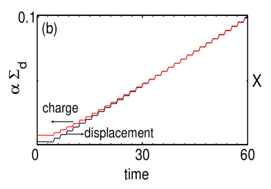
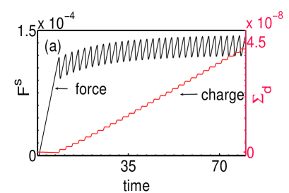
We now consider the numerical solution of Eqs. (6,7,8,9). The force-displacement curve is shown in Fig. 1(a) for ( ) along with the cumulative charge transferred to the substrate . Clearly, the mean force gradually increases and saturates, a feature seen in experiments (Fig. 3(a) of Ref. BP00 ). Further, the average slope of as a function of time (in the asymptotic regime) is proportional to that for the displacement . Using a proper scale factor these two curves can be made to collapse onto a single curve shown in Fig. 1 (b) for . Thus, the model recovers the correlation between the stick-slip events and charge transfer.
We now examine the influence of the normal force . We have calculated displacement and cumulative charge transferred for ( ). In each case, and curves collapse onto a single curve for a proper choice of the scale factor . In particular, for and the values of respectively are and . Then, the ratio of the maximum deviation () to the mean (), is . This compares well with scatter in in experiments for (Fig. 3(b) inset of BP00 ). This shows that the change in (equivalently ) is small for the limited range of normal loads considered ( or ).
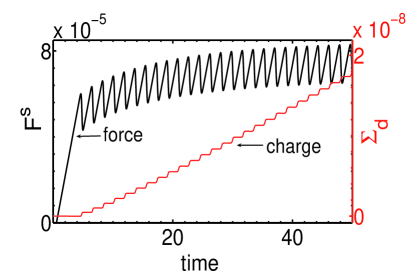
In our model, as , we expect the scale factor to depend on the load. However, the area changes by a factor 1.34 when is changed from to which translates to a small change (decrease) in (or equivalently ). However, for higher load levels the value of the scale factor does change significantly. To see this, consider a much higher load level, say . The scale factor for this case is is , which falls well outside the mean value of for the limited load range . A plot of the force-displacement curve is shown in Fig. 2(a) for along with the cumulative charge transferred to the substrate . Thus, the lack of dependence of on load is clearly due to the limited range of loads studied in Ref. BP00 . The plot also shows that the model predicts fewer stick-events on an average with increase in for the same scan length, a feature taken as a support for electronic origin of friction BP00 . The above features emerge due to the separation of time scales of the stick (charging) phase and the slip (charge transfer) phase.
As stated earlier, at the charge density level of , the slip threshold is controlled by the friction threshold . However, when is increased, the onset of the first force drop increases. A plot of the force-displacement curve is shown in Fig. 2(a) for keeping . (The cumulative charge transferred to the substrate is also shown.) It is clear that the threshold for the first force drop as also the average asymptotic value of has increased from those for . (Compare with Fig. 1 (a).)
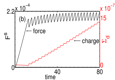
As stated earlier, the results of the Model II are very similar to those of Model I. To see this, we first note that the equation for (Eq. 10) for Model II differs from that of Model I [Eq. (6)] by a factor . However, the near saturation value of is almost entirely controlled by Eq. (7). Thus, the value of where the instability occurs can be estimated by inserting the near saturation value of in . This gives a value . The rest of the parameters are the same. A plot of the force-displacement curve shown in Fig. 3 for . For the sake of comparison, we have also shown the force-displacement curve for Model I on the same plot as a dashed line. As can be seen, except for a phase factor, the two curves follow the same behavior.
The above calculations are for . However, in general, they can be different from unity. Figure 4 shows the force-displacement curves for both Model I and II for and . Again the difference between the two models is only in the phase.


We now consider estimating the value of the scale factor . Since the force and charge transferred curves for a given scan length collapse onto a single curve only in the asymptotic stick-slip regime [Fig. 1(b)], we can use valid on an average. Using this in
| (13) |
gives
| (14) |
where is the mean value of () in the asymptotic stick-slip regime. Using and leads to for . This value is high even after discounting the ideal nature of the model.
This prompted us to look for possible contributions that affect the scale factor . A cursory look at contact charge image in Fig. 2 of Ref. BP00 shows that the mean charging radius is surprisingly large, typically 10-20 times the contact radius with charge density . While the authors make no comment on such a high value of charging radius, one possibility is that charge deposited spreads (possibly after the slip event) due to electro-static repulsion Lowell80 ; Lee94 . However, the model uses the natural choice that charging area is equal to the contact area for that load. Thus, independent of the physical causes for such a large charging area, we should either use a larger contact area with or use higher charge density (by a factor ) keeping the contact area fixed. Using in place of , we get . This value is consistent with the reported value. Finally, we note that the value of is nearly the same for smooth sliding conditions as is exact.
Another factor that affects contact charging is the surface roughness. The influence of surface roughness on friction is well known in tribology. Several models have been proposed to calculate the contribution arising from roughness GW66 ; Nayak71 ; Bush75 . The topic has been revisited recently with a view to accommodate the influence of a hierarchy of roughness scales Yang08 . However, for the load levels considered here, it is easy to show that this is likely to contribute about Yang08 . Here, it may be relevant to point out that roughness in this case is likely to be dynamical due to the sliding over long intervals of time Berman98 .
V Summary and Discussion
In summary, we have developed a model for the stick-slip dynamics observed when the tip of the cantilever of a surface force apparatus is dragged on a substrate. Equations of motion for the center of the contact area and penetration depth are set up by considering the tip as a single smooth asperity contacting with a smooth surface for which contact mechanics is applicable. Further, the time dependent contributions arising from visco-elastic nature of the PMMA substrate and possible plastic deformation of the softer PMMA are included. The model exhibits stick-slip dynamics for a range of values of the parameters. To account for the contact charging at the area of contact, these equations are coupled to an equation of motion for the total contact charge developed on contact. Charging occurs during the stick phase and transfer of charge to the substrate occurs during slip phase.
The model captures several features of the experiment. First, the correlation between the stick-slip events and charge deposited on the PMMA substrate is reproduced. This is to be expected as the contribution from contact charging ( ) is orders of magnitude smaller than the static friction threshold () or even sliding frictional threshold. Second, for higher load, the model predicts fewer events for the same scan length. Third, lack of dependence of the scale factor on normal load observed in experiments is traced to the small range of values studied in Ref. BP00 . Indeed, Eq. (14) shows that the scale factor is inversely proportional to the area of contact for the load. Fourth, in the model, contact charging is equal to the contact area for the load. If this relation is used, the magnitude of the scale factor turns out to be nearly 50 times the experimental value. However, as discussed, the experimental charging area is times the theoretically calculated contact area for that load (see Fig. 2 of Ref. BP00 ). Using this value in place of the contact area in Eq. (14) gives . This value is close to the measured value. Since the lack of dependence of on load together with the value of has been interpreted to mean that friction is controlled by contact charging, it is necessary to check the lack of dependence of over larger range of normal loads before the suggestion can be taken seriously. Further, the value of should be nearly same for smooth sliding conditions as well. All these features follow naturally due to the separation of time scales of stick and slip events. Stick-slip events are not affected by contact charging for the charge levels in Ref. BP00 . Instead plastic deformation of the interface material is the cause of slip. At a mathematical level the instability is due to a competition between the visco-elastic and plastic deformation time scales with the applied time scale. As most experimental features are captured, the model provides an alternate explanation for the results. Lastly, the fact that sliding friction is lower than static friction comes out naturally from the equations of motion.
Finally, the model should be applicable to other stick-slip phase observed in frictional sliding experiments where plastic deformation is significant, including stick-slip observed during scratching of polymer sheets Li96 ; VH00 ; HV00 .
ACKNOWLEDGMENTS
G. A would like to acknowledge financial support from BRNS grant 2007/36/62-BRNS and Raja Ramanna Fellowship scheme.
References
- (1) J. Gao, W. D. Luedtke, D. Gourdon, M. Ruths, J. N. Israelachvili and Uzi Landman, J. Phys. Chem. B 108, 3410 (2004).
- (2) A. M. Homola, J. N. Israelachvili, P. M. Mcguiggan and M. L. Gee, Wear 136, 65 (1990).
- (3) R. W. Carpick, N. Agrait, D. F. Ogletree, and M. Salmeron, Langmuir 12, 3334 (1996).
- (4) A. Berman, S. Steinberg, S. Campbell, A. Ulman and Jacob Israelachvili, Tribolgy Letters 4, 43 (1998).
- (5) Y. Mo, K. T. Turner and I. Szlufarska, Nature (London) 457, 1116 (2009).
- (6) B. Luan and M. O. Robbins, Phys. Rev. E 74, 026111 (2006); S. Cheng, B. Luan and M. O. Robbins, Phys. Rev. E 81, 016102 (2010) and the references there-in.
- (7) K. L. Johnson, K. Kendall and A. D. Roberts, Proc. R. Soc. London A 324, 301 (1971).
- (8) K. L. Johnson, Contact Mechanics (Cambridge University Press, Cambridge, England 1985.)
- (9) I. Szlufarska, M. Chandross, and R. W. Carpick, J. Phys. D, Appl. Phys. 41, 123001 (2008).
- (10) F. Heslot, T. Baumberger, B. Perrin, B. Caroli and C. Caroli, Phys. Rev. E 49, 4973 (1994); T. Baumberger and C. Caroli, Adv. Phys. 55, 279 (2006).
- (11) T. Baumberger, P. Berthoud and C. Caroli, Phys. Rev. B 60, 3928 (1999): L. Bureau,T. Baumberger and C. Caroli, Euro. Phys. J. E 19, 163 (2006).
- (12) Y. Estrin and Y. Bréchet, Pure and Appl. Geophys. 147, 745 (1996).
- (13) U. Landman, W. D. Luedtke, N. A. Burham and R. J. Colton, Science, 248, 454 (1990); U. Landman, W. D. Luedtke and E. M. Ringer, Wear 153, 3(1992).
- (14) U. Landman, W. D. Luedtke and J. Gao, Langmuir 12, 4514 (1996).
- (15) M. R. Sorensen, K. W. Jacobsen and P. Stoltze, Phys. Rev. B 53, 2101 (1996).
- (16) C-K Chen, B-H Chen and Y-T Yang, Nanotechnology 15, 1771 (2004).
- (17) R. Budakian and S. J. Putterman, Phys. Rev. Lett. 85, 1000 (2000).
- (18) A. D. Roberts, J. Phys D: Appl. Phys. 10, 1801 (1977).
- (19) H. Graf Von Harrach and B. N. Chapman, Thin Solid Films 13, 157 (1972).
- (20) A. R. Akande, J. Electrostatics 63, 1025 (2005).
- (21) Lieng-Huang Lee, Journal of Electrostatics 32, 1 (1994).
- (22) J. Lowell and A. C. Rose-Innes, Adv. Phys. 29, 947 (1980).
- (23) G. Ananthakrishna and Jagadish Kumar, in the Proceedings of II International Workshop on Correlation Microsctructure - Properties and Multiscale Modelling of Plasticity (Fuenteheridos, Spain, June 17-21,2009), (Eds.) A. Dominguez-Rodriguez, D. Gomez-Garcia, A Munos Bernab University of Sevilla, Spain, 2009, pp. 91-94; See also Jagadish Kumar, Stick-slip dynamics in peeling of an adhesive tape and surface force apparatus, Doctoral Thesis, Indian Institute of Science, Bangalore, India, (2010).
- (24) E. Charrault, C. Gauthier, P. Marie, and R. Schirrer, Langmuir 25, 5847 (2009).
- (25) D. Maugis, J. Colloid Interface Sci. 150, 243 (1992).
- (26) Z. H. Stachurski, Prog. Polym. Sci. 22, 407 (1997).
- (27) G.Ananthakrishna, Phys. Rep. 440, P 113-259 (2007).
- (28) J. A. Hurtado K-S Kim, Proc. Roy. Soc. London, A 455, 3363 (1999).
- (29) W. P. Vellinga and C. P. Hendriks, Phys. Rev. E 63, 066121 (2001).
- (30) A. S. Nowick and B. S. Berry, Anelastic Relaxtion of Crystalline Solids New York 1972.
- (31) R. W. Hertzberg, Deformation and Fracture Mechanics of Engineering Materials, (John Wiley & Sons,Inc, NewYork,1996).
- (32) G. Ananthakrishna and M. S. Bharathi, Phys. Rev. E 70, 26111 (2004).
- (33) S. Kok, M. S. Bharathi, A. J. Beaudoin, G. Ananthakrishna, C. Fressengeas, L. P. Kubin, and M. Lebyodkin, Acta Mater. 51, 3651 (2003).
- (34) A better way of dealing with plastic deformation in the (or in the ) direction would be to write an equation of plastic strain rate and couple it to the equation of motion for (or for ). This is not attempted here since the equations of motion are already complicated.
- (35) J. A. Greewood and J. B. P Williamson, Proc. Roy. Soc. London A 295, 300 (1966) .
- (36) P. R. Nayak, J. Lubr. Technol. 93, 398 (1971).
- (37) A. W. Bush, R. D. Gibson and T. R. Thomas, Wear, 35, 87 (1975).
- (38) C. Yang and B. N. J. Persson, Phys. Rev. Lett. 100, 024303 (2008) and the refences therein.
- (39) K. Li, B. Y. Ni and J. C. M. Li, J. Mater. Res. 11, 1574 (1996).
- (40) W. P. Vellinga and C. P. Hendriks, Tribology Lett. 9, 119 (2000).
- (41) C. P. Hendriks and W. P. Vellinga, Rev. Sci. Instrum. 71, 2391 (2000).