Effects of optical fields on the tunneling time of chiral electrons in graphene
Abstract
The influences of optical fields on the tunneling time in graphene are investigated in real time using the finite-difference time-domain method. The tunneling time of electrons irradiated by an optical field is significantly different from that observed in traditional quantum tunneling. We found that when the barrier width increases, the group delay becomes constant for the reflected wave packet, but increases linearly for the transmitted wave packet. This peculiar tunneling effect can be attributed to current leakage in a time-dependent barrier generated via the optical Stark effect.
pacs:
42.65.-k, 68.65.-k, 73.40.GkQuantum tunneling time has received much attention since MacColl pointed out that it takes no approximate time 1LA ; 2EH ; 3HG . The question about how long it takes an electron to tunnel through a potential barrier is still replete with controversy. The debates center around the definition of tunneling time and its exact physical meaning. Hartman calculated the group delay or phase time and found that the the group delay becomes constant while the barrier length increases 4TE . Thus, with a wider barrier, superluminal group velocities can be observed. Recently, Winful proposed that the group delay in tunneling represents a lifetime of stored energy escaping through both sides of the barrier, not a transit time 3HG ; 5HG ; 6HG . However, unlimited group velocity is not a meaningful concept in tunneling and does not imply superluminality.
In the meantime, many optical and acoustic experiments have been carried out to determine tunneling time. Steinberg et al. 7AM measured the time delay for a photon to tunnel across a one-dimensional photonic band-gap material. They reported that the group velocity for single-photon tunneling is about , where is the speed of light in vacuum. The authors attributed superluminality to the fact that the wavepacket may be reshaped in the tunneling process. Longhi et al. 8SL used a relatively long optical pulse (380ps) and conformed that there is no distortion in the the tunneling process. Even though the exact physical meaning of these experimental results is controversial, there is no doubt that there is a finite duration for the photon or phonon tunneling process. However, few direct experiments have shown that there is finite tunneling time in the quantum particle tunneling process.
There are some difficulties in the measurement of the tunneling time of electrons. For instance, the coherence time of electrons must be long enough to ensure that the tunneling process is an elastic transport. It seems that the graphene is an ideal candidate material for this. The reported electron mobility in graphene at room temperature is in excess of 15,000 , and the limit of electron mobility at room temperature is about 200,000 in theory 9KS ; 10AK ; 11AH . To measure the tunneling time, a high time-resolved technique must be used, so the injected electrons must be generated using ultrafast laser beams (e.g., generated via coherent one- and two-photon absorption 12RA ; 13EJ ; 13HZ ), or the barrier must be controlled by the ultrafast laser beams 14JT ; 15JT . Furthermore, because of the existence of zero-point fields, the influences of electromagnetic fields on the tunneling time must be carefully treated. When the electromagnetic fields are included, the barrier is time dependent. The situation is quite different when a time-dependent potential barrier is taken into account. For instance, for an opaque rectangular barrier with a small time-dependent modulation, the traversal time of Büttiker and Landauer is proportional to the barrier width 16MB .
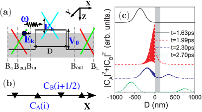
In this Letter, we investigate the influences of electromagnetic fields on the tunneling time of Dirac electrons in graphene. We consider a rectangular potential barrier with height and width [see Fig. 1 (a)]. The Fermi level lies in the valence band in the barrier and in the conduction band outside the barrier. A -direction polarized laser beam is propagated perpendicular to the layer surface with a detuning . We choose to ensure that there is no interband absorption inside the barrier, and to guarantee that the influence of the optical field outside the barrier can be neglected. In a single layer graphene, a perfect transmission through a potential barrier in the normal direction is expected, and there is no Hartman effect 17MI ; 17MI_B ; 17MI_C ; 18ZH . However, if the barrier is irradiated by a intense optical field, the conduction band and valence band is mixed, the chiral symmetry of the Dirac electrons is broken, and the perfect tunneling is strongly suppressed 15JT . Thus, the Hartman effect may appear if the electromagnetic field is included.
In order to study such a time-dependent scattering process, we employ the finite-difference time-domain (FDTD) method to solve the time-dependent Dirac equation numerically. In the FDTD method, the time-dependent Dirac equation in point is replaced by a finite set of finite differential equations
| (1a) | ||||
| (1b) | ||||
where denotes the grid of point of the space [see Fig .1(b)], is the wave function of Dirac electrons, is the Fermi velocity, is the height of the potential barrier, and and are the matrix elements of the interaction Hamiltonian 13EJ
| (2) |
where is the electron charge and are the vector potentials of the electromagnetic field.
Thus, by numerically solving Eq. (1a) and Eq. (1b) directly in the time domain, we can demonstrate the propagation of a wave packet through a barrier in real time. For computational stability, we choose the space increment nm and the time increment ps. As an example, the evolution of a wave packet through a barrier is shown in Fig. 1(c). At the input boundary , a Gaussian electronic wave packet is injected. For the convenience of demonstration, a short pulse is used: the peak position ps, and the pulse width ps. From Fig. 1(c), we find that when the sample is irradiated by an intense nonresonant laser beam, a reflected wave packet appears, and the perfect transmission is suppressed.
Under an intense optical field, the light-induced band shift can also create a dynamic gap at small detuning. As is seen in traditional quantum tunneling (e.g., the Hartman effect), the tunneling time of Dirac electrons should be constant while the barrier width increases. To verify this, we studied the group delay (i.e., the delays of the peak of the reflected and transmitted pulse) of Dirac electrons through a potential barrier generated by an intense light beam. In order to reduce the distortion, a relatively long plus is used: the peak position ps, and the pulse width ps.
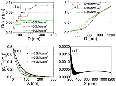
Fig. 2(a) shows the group delay for the reflected wave packet as a function of barrier width for different pump intensities. As seen in traditional quantum tunneling, the group delay is saturated by increasing the barrier length. For MW/cm2, MW/cm2, and MW/cm2, the corresponding saturated delays are about , , and ps, respectively. The delay can also be explained by the tunneling depth or dwell time. As shown in Fig. 2(c), the spatial probability density distributions in the barrier are well fitted by using the exponential function . For MW/cm2, MW/cm2, and MW/cm2, the corresponding tunneling depths are , , and nm, respectively. In this way, we extract that the corresponding tunneling delays are about , , and ps, respectively. These results are consistent with the saturated delay obtained in Fig. 2(a). Another interesting phenomenon is that the group delay for the reflected wave packet takes on the quantized values . We find that ps is equal to the period of the optical field. The quantized group delay is therefore caused by the optical modulation of the reflected wave packet.
The case is quite different for the transmitted wave packet. As shown in Fig. 2(b), when the barrier width nm, the group delay increases linearly with increasing barrier width. The group velocity is about m/s and is the same as the Fermi velocity of Dirac electrons in graphene. This result can be explained by the time-dependent potential barrier. In a time-dependent potential barrier, the energy storage depends on time. Variations in energy storage will lead to an extra leakage current. The dynamic gap caused by the optical field is therefore not a complete gap, and the probability density distribution on the right side of the barrier is no longer exponential decay [see Fig. 2(d)]. Since the amplitude of the extra leakage current is quite small, it has little effect on the reflected wave packet but still determines the group delay for the transmitted wave packet at large barrier widths. For small barrier widths, since the tunneling current is much larger than the extra leakage current, the time delays of the reflected and transmitted wave packets are equal. From Fig. 2(b), we see that the amplitude of the extra leakage current strongly depends on the pump intensity. Specificially, for MW/cm2, the group delay increases linearly with increasing barrier width when nm, but for MW/cm2 the linearly increasing delay appears when nm. However, the group velocity of the extra leakage current is independent of pump intensity. Thus, even with a quite small time-dependent modulation, no ”Hartman effect” occurs.
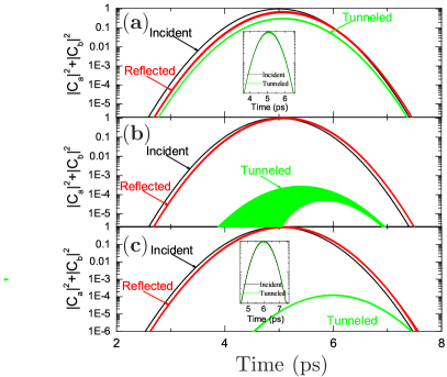
The existence of current leakage in a time-dependent barrier can also be confirmed by the shape of tunneled pulses. In a thin barrier, the amplitude of the tunneling current is much larger than the amplitude of the extra leakage current induced by the time-dependent modulation. The tunneling time of the transmitted and reflected wave packet is equal [see Fig. 3(a)], and the distortion is quite small [see the inset of Fig. 3(a)]. When the thickness of the barrier increases, the tunneling rates decrease rapidly. In a thick barrier, the amplitude of the extra leakage current is comparable with that of the tunneling current. Since the tunneling times of the extra leakage current and the tunneling current are different, a serious distortion can be found in the tunneled pulse [see Fig. 3(b)]. However, if the width of the barrier is large enough (e.g., nm), the tunneling rate is very small, and the extra leakage current is the main contributor to the tunneled pulse. Thus, the tunneling times of the transmitted and reflected wave packets are different [see Fig. 3(c)], and there is no distortion on this scale [see the inset of Fig. 3(c)].
The tunneling delay for a time-dependent potential barrier might help us to understand quantum tunneling. For example, traditional definitions of tunneling time are unsuitable for the system we studied. In the traditional definitions, the tunneling time of the transmitted and reflected wave packets are equal for a symmetrical barrier. More importantly, if the quantum fluctuation or the zero-point field is included, all potential barriers are time dependent.
In conclusion, we have calculated the influence of optical fields of chiral tunneling time in graphene using the FDTD method. We find that the group delay of the reflected packet is also saturated as the barrier width increases. However, the delay increases linearly with barrier length for the transmitted wave packet. This peculiar tunneling effect is attributed to current leakage in a time-dependent barrier generated via the optical field. Thus, the zero-point field may have an important influence on the tunneling time of electrons, and should be carefully treated. These unique transport properties of dressed Dirac electrons in graphene might be important in the understanding of quantum tunneling.
This work was supported by the NSFC Grant Nos. 10904059 and 10904097, the NSF from Jiangxi Province Nos. 2008GZW0003 and 2009GQW0017, the Open Research Fund of State Key Laboratory of Millimeter Waves No. K200901, and the Program for Innovative Research Team in Jiangxi Province.
References
- (1) L. A. MacColl, Phys. Rev. 40, 621 (1932).
- (2) E. H. Hauge and J. A. Stövneng, Rev. Mod. Phys. 61, 917 (1989), and references therein.
- (3) H. G. Winful, Physics Reports 436, 1 (2006), and references therein.
- (4) T. E. Hartman, J. Appl. Phys. 33, 3427 (1962).
- (5) H. G. Winful, Opt. Express 10, 1491 (2002).
- (6) H. G. Winful, Phys. Rev. Lett 90, 023901 (2003).
- (7) A. M. Steinberg, P. G. Kwiat, and R. Y. Chiao, Phys. Rev. Lett 71, 708 (1993).
- (8) S. Longhi, M. Marano, P. Laporta, and M. Belmonte, Phys. Rev. E 64, 055602 (2001).
- (9) K. S. Novoselov, A. K. Geim, S. V. Morozov, D. Jiang, Y. Zhang, S. V. Dubonos, I. V. Grigorieva, A. A. Firsov, Science 306, 666 (2004).
- (10) A. K. Geim, and K. S. Novoselov, Nature Materials 6, 183 (2007).
- (11) A. H. Castro Neto, F. Guinea, N. M. R. Peres, K. S. Novoselov, and A. K. Geim, Rev. Mod. Phys. 81, 109 (2009).
- (12) R. Atanasov, A. Haché, J. L. P. Hughes, H. M. van Driel, and J. E. Sipe, phys. Rev. Lett. 76, 1703 (1996).
- (13) E. J. Mele, P. Kr al, and D. Tom anek, Phys. Rev. B 61, 7669 (2000).
- (14) H. Zhao, X. Pan, A. L. Smirl, R. D. R. Bhat, A. Najmaie, J. E. Sipe, and H. M. van Driel, Phys. Rev. B 72, 201302(R) (2005).
- (15) J. T. Liu, F. H. Su, and H. Wang, Phys. Rev. B 80, 113302 (2009).
- (16) J. T. Liu, F. H. Su, H. Wang, and D. X. Hua, The influence of the optical Stark effect on chiral tunneling in graphene, arXiv:1007.3430v1, (submitted to Appl. Phys. Lett.).
- (17) M. Büttiker and R. Landauer, Phys. Rev. Lett. 49, 1739 (1982).
- (18) M. I. Katsnelson, K. S. Novoselov, and A. K. Geim, Nature Physics 2, 620 (2006).
- (19) C. H. Park, L. Yang, Y. W. Son, M. L. Cohen, S. G. Louie, Nature Physics 4, 213 (2008).
- (20) Z. Z. Zhang, Kai Chang, and F. M. Peeters, Phys. Rev. B 77, 235411 (2008).
- (21) Z. H. Wu, K. Chang, J. T. Liu, X. J. Li, and K. S. Chan, J. Appl. Phys. 105, 043702 (2009).