Spin waves in zigzag graphene nanoribbons and the stability of edge ferromagnetism
Abstract
We study the low energy spin excitations of zigzag graphene nanoribbons of varying width. We find their energy dispersion at small wave vector to be dominated by antiferromagnetic correlations between the ribbon’s edges, in accrodance with previous calculations. We point out that spin wave lifetimes are very long due to the semi-conducting nature of the electrically neutral nanoribbons. However, application of very modest gate voltages cause a discontinuous transition to a regime of finite spin wave lifetime. By further increasing doping the ferromagnetic alignments along the edge become unstable against transverse spin fluctuations. This makes the experimental detection of ferromagnetism is this class of systems very delicate, and poses a difficult challenge to the possible uses of these nanoribbons as basis for spintronic devices.
Graphene is being hailed as the big promise for nanoelectronics and spintronics. Its unique transport properties are expected to play a fundamental role in the develpment of new technologies Fujita et al. (1996); Okada and Oshiyama (2001); Muñoz-Rojas et al. (2009). New physics is also emerging from the interplay between low dimensionality, a bipartite lattice and electron-electron interaction. One of the most striking properties of graphene nanoribbons is the possibility of spontaneous magnetization Son et al. (2006a, b); Pisani et al. (2007). This, combined with the long spin-coherence times of electrons propagating across graphene, indicates that this system is a strong candidate for future spintronics applications.
The ground state properties of magnetic graphene nanoribbons have been extensively explored by a variety of methods. Recent works have investigated the properties of static excited states based on adiabatic approximations Yazyev and Katsnelson (2008); Rhim and Moon (2009). This approach has been employed to describe the lowest-lying excitations of magnetic metals with relative success. However, it is well known that it misses important features of the excited states, such as its finite lifetime. This arises due to the coupling between spin waves and Stoner excitations, a distinctive feature of itinerant magnets. Moreover, these recent investigations of excited states seem to have disregarded the antiferromagnetic coupling between the magnetizations on opposite edges of graphene nanoribbons. As we shall see, this leads to an incorrect prediction concerning the wave vector dependence of low energy spin excitations. This has already been demonstrated more than a decade ago in the seminal work by Wakabayashi et al. Wakabayashi et al. (1998). Those authors used an itinerant model to describe the electrons in graphene nanoribbons of various widths. They showed clearly the presence of a linear term in the spin wave dispersion relation for small wave vector.
One interesting feature of magnetic graphene nanoribbons is that the spins along each border are ferromagnetically coupled to each other, but there is an antiferromagnetic exchange coupling between the two opposite borders. This coupling is mediated by the conduction electrons, and decreases as the ribbon width is increased. Thus, it may appear, at first sight, that this antiferromagnetic coupling should be unimportant in wide ribbons. It has been shown, however, that this coupling is extremely long ranged in graphene and other related materials Venezuela et al. (2009); Costa et al. (2005, 2008); Kirwan et al. (2008, 2009). Thus, even in rather wide nanoribbons this coupling asserts itself, as we shall see.
We describe the electrons in graphene using a Hubbard model,
| (1) |
where are hopping integrals () and on-site energies (), is the effective intra-atomic Coulomb interaction and creates one electron at the atomic state at site with spin . Here we only consider nearest neighbor hoppings. We took eV (), as in Ref. Jung and MacDonald (2009a). This model provides a good qualitative description of electrons in graphene, as well as the magnetic effects deriving from the screened Coulomb interaction. The magnetic ground state is described self-consistently within a mean-field approximation. We impose local charge neutrality on every atom in the ribbon and determine the magnetic moment of each atom in the unit cell individually. We find that the magnetic moment of the edge atoms is and decays rapidly towards the center of the ribbon, in close agreement with calculations based on density functional theory Yazyev and Katsnelson (2008). Notice that we consider the effective Coulomb interaction to be active in every atom in the system. The fact that the magnetization is essentially localized at the edges emerges naturally from our self-consistent treatment.
The spin excitations are extracted from the properties of the transverse dynamic susceptibility,
| (2) |
where and are the spin raising and lowering operators. By treating the Coulomb interaction term within a random phase approximation we obtain a closed equation of motion for (the Fourier transform of ) in terms of the mean-field susceptibility Barbosa et al. (2001),
| (3) |
where and are matrices comprising all magnetic sites in the system and is the identity matrix with the same dimension as and . The notation used in the equation above is schematic. A more precise statement on the form of the calculated susceptibility is given below.
The spectral density
| (4) |
where denotes the imaginary part, may be interpreted as the density of states of magnons in the system. The dynamic susceptibility just described is the response of the system to an externally applied field of frequency transverse to the ground state magnetization direction; spin waves appear as peaks in the spectral density.
The graphene nanoribbons we study have translation symmetry along the ribbon length (denoted here by ), but not along the ribbon width (). It is convenient to define a mixed Bloch-Wannier basis to describe the electronic states,
| (5) |
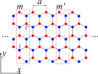
where is the annihilation operator for a Wannier state at a site in unit cell , is the distance between unit cells along the ribbon length and Å is the carbon-carbon distance. In this representation, the transverse dynamical susceptibility is a matrix, where label sites within a unit cell; each element of such matrix is a function of the wave vector along the length of the ribbon, as well as of the energy . The unit cell is depicted in Fig. 1
We start by discussing the spectral density for a nanoribbon of fixed width. In Fig. 2 we plot the spectral density as a function of for fixed values of wave vector , for a ribbon with 16 atoms in the cross-section. The main contribution for the excitations should come from the edges, where most of the magnetic moment of the system is concentrated. Thus, we only need to plot the spectral density projected on the “up” edge, that we label as (the spectral density at the “down” edge has similar behavior). Spin wave energies increase with wave vector, as usual, but the dependence is not quadratic, as would be expected from a simple ferromagnet.
A plot of the dispersion relation deduced from the peak positions (Fig. 2(c)) shows that the dispersion is linear quite far out into the Brillouin zone (20% of the zone boundary), and in fact is quasi linear at large wave vectors as well. This may be understood if we map the spin degrees of freedom of this system onto a simple effective spin model, as illustrated in ref. Wakabayashi et al. (1998).
Calculations of spin excitation energies based on an adiabatic approach have been reported recently Yazyev and Katsnelson (2008). They find a quadratic energy-wave vector dispersion relation with a spin wave exchange stiffness of 320 meVÅ2. We plot this dispersion relation in Fig. 2(c) for comparison. Although the energies found using the adiabatic approach are of the same order as those obtained via dynamical calculations, the discrepancy between the dependencies on wave vector is remarkable.
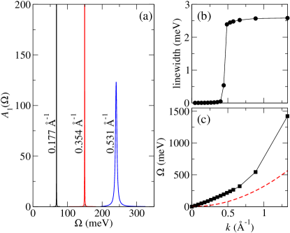
In Fig. 2(a) we see that the spin wave peaks are extremely narrow for small wave vectors, indicating a very large spin wave lifetime. This is compatible with the existence of a threshold for Stoner excitations of the order of the semiconducting gap in these ribbons. Only spin waves with energies equal to or larger than this gap are damped. This means that the low energy spin dynamics (represented by long wavelength spin waves) may be well described by effective localized spins hamiltonians, but as the wavelength of the excitation become smaller the itinerant nature of the system reveals itself. Thus, a simple ferromagnetic Heisenberg hamiltonian is clearly not the appropriate model to describe the spin degrees of freedom of this fascinating system.
One very attractive feature of graphene is the possibility of controlling its carrier density by electrostatic gating. In the present case this feature opens up a very exciting possibility: by controlling the electron density we may be able to tune the relaxation time of spin excitations in graphene. As shown above, long wavelength spin waves are essentially undamped in electrically neutral graphene ribbons. In fig. 3 we show that very modest changes in the electron density can induce rather large damping, reducing considerably the relaxation time for spin excitations and shifting their energies. The origin of this damping is simple to grasp: the density of Stoner modes is very small at small energies in undoped graphene ribbons due to the fact that the density of states near the Fermi level is zero (the antiferromagnetic, undoped nanoribbon is semiconducting). As the density of states is increased by the gate voltage, is increased for energies close to , giving rise to a significant enhancement of the density of Stoner modes. As it is well known Barbosa et al. (2001); Muniz and Mills (2002); Tang et al. (1998); Costa et al. (2003), spin wave damping in itinerant systems occurs through the decaying of magnons into Stoner modes, a mechanism very similar to the Landau damping of plasmons in metals. In Fig. 3(b) we show how the density of Stoner modes at the spin wave energies (given by the spectral function associated with the non-interacting susceptibility ) is enhanced by increasing electron density.
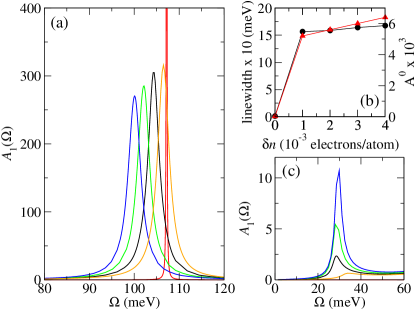
It is also clear from Fig. 3 that the extra damping is accompanied by a shift in the spin wave energy. Once again, this is related to the enhancement of the density of Stoner modes, via the Kramers-Krönig relation. The non-interacting susceptibility enters in the denominator of the dynamic susceptibility , as indicated in Eq. 3. Its imaginary part is responsible for the finite lifetime of spin waves in itinerant magnets; its real part produces a shift in the spin wave frequencies, in much the same way as dissipative forces shift the natural frequency of mechanical oscillators. Thus, enhancement of damping also implies a larger frequency shift.
There is another facet to the onset of strong spin wave damping in graphene nanoribbons. Spin excitations with infinite (or extremely long) lifetimes are associated with strongly localized spins, whereas strongly damped spin waves are found in systems where magnetism is itinerant in nature. It is very rare that one system can be tuned to be either a localized or an itinerant magnet with the change of a single parameter, easily accessible experimentally. It is an extremely exciting prospect that this kind of control is available in graphene nanoribbons.
The lifetime of spin waves in zigzag graphene nanoribbons can be dramatically reduced, as we just saw, by very modest doping (as small as electons/atom). By further increasing doping we notice that the ferromagnetic alignment along the borders becomes unstable. A sign of this instability is the appearance of a very soft spin wave mode as doping increases, as can be seen in Fig. 3(c).
The instability of the ferromagnetic alignment can be confirmed by the behavior of the mean-field transverse susceptibility at zero frequency, as a function of wave vector, Edwards (1979). In a stable ferromagnetic system has a single maximum at , as illustrated by the zero doping curve in figure 4(a). As doping increases, a peak develops close to , until, at large enough doping (in this case, 0.01 electrons/atom), a pronounced maximum appears at a finite value of . The existence of peaks in at finite values of means that the true ground state of this system is not ferromagnetic along the edges, but most probably a spin density wave characterized by those finite wave vectors.
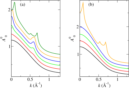
One virtue of our simple model is that we can tune parameters and explore various behaviors. By changing the strength of the Coulomb interaction we noticed that the doping level at which the instability appears changes. This is illustrated in Fig. 4 for two different values of ; for eV the ferromagnetic alignment becomes unstable at electrons/atom, whereas for eV it is stable for doping levels as large as electrons/atom. It would be interesting to build a phase diagram, but our intention here is to point out the dependence and the general trend.
The stability analysis we performed is complementary to that presented in references Jung and MacDonald (2009a, b); Sawada et al. (2009), where energy differences between collinear and non-collinear configurations in the direction transverse to the ribbon were analized. To the best of our knowledge, ours is the first analysis that take into account the possibility of non-collinear ordering along the ribbon’s edges.
We have investigated wider nanoribbons (up to 32 atoms wide, although this is only limited by computer time). The most important effects of increasing the ribbon width are i) the enhancement of a quadratic contribution to the spin wave dispersion relation (due to the partial suppression of antiferromagnetic coupling between edges) and ii) the reduction of the doping range (for fixed ) within which ferromagnetism along the borders is stable.
In conclusion, we have shown that the lifetimes of spin excitations in zigzag graphene nanoribbons can be tuned by the application of modest gate voltages. This allows, at least in principle, electrical control of the magnetic relaxation rate. We have also demonstrated that there is a sharp transition between the character of the spin excitations in neutral and doped nanoribbons: while in neutral ribbons the long wavelength excitations have essentially infinite lifetime (a feature shared with magnetic insulators), any amount of doping, however small, leads to finite lifetimes (as in magnetic metals). Finally, we showed that further increasing doping makes the ferromagnetic alignment unstable against transverse spin fluctuations, a fact that should be carefully invesigated if these systems are to be used in technological applications. We are confident that our results open very exciting possibilities both in spintronics technology and for fundamental understanding of magnetism at the nanoscale.
Acknowledgements.
We are extremely grateful to R. B. Muniz, D. L. Mills and M. S. Ferreira for discussions and critical readings of the manuscript. The research of A.T.C. and A.L. was supported by CNPq and FAPERJ (Brazil). F.C. acknowledges a scholarship from CNPq (Brazil). We also acknowledge partial financial support from the National Institute of Science and Technology - Carbon Nanomaterials (INCT-NT).References
- Fujita et al. (1996) M. Fujita, K. Wakabayashi, K. Nakada, and K. Kusakabe, J. Phys. Soc. Jpn. 65, 1920 (1996).
- Okada and Oshiyama (2001) S. Okada and A. Oshiyama, Phys. Rev. Lett. 87, 146803 (2001).
- Muñoz-Rojas et al. (2009) F. Muñoz-Rojas, J. Fernández-Rossier, and J. J. Palacios, Phys. Rev. Lett. 102, 136810 (2009).
- Son et al. (2006a) Y.-W. Son, M. L. Cohen, and S. G. Louie, Nature (London) 444, 347 (2006a).
- Son et al. (2006b) Y.-W. Son, M. L. Cohen, and S. G. Louie, Phys. Rev. Lett. 97, 216803 (2006b).
- Pisani et al. (2007) L. Pisani, J. A. Chan, B. Montanari, and N. M. Harrison, Phys. Rev. B 75, 064418 (2007).
- Yazyev and Katsnelson (2008) O. V. Yazyev and M. I. Katsnelson, Phys. Rev. Lett. 100, 047209 (2008).
- Rhim and Moon (2009) J. Rhim and K. Moon, Phys. Rev. B 80, 155441 (2009).
- Wakabayashi et al. (1998) K. Wakabayashi, M. Sigrist, and M. Fujita, J. Phys. Soc. Jpn. 67, 2089 (1998).
- Venezuela et al. (2009) P. Venezuela, R. B. Muniz, A. T. Costa, D. M. Edwards, S. R. Power, and M. S. Ferreira, Phys. Rev. B 80, 241413(R) (2009).
- Costa et al. (2005) A. T. Costa, D. F. Kirwan, and M. S. Ferreira, Phys. Rev. B 72, 085402 (2005).
- Costa et al. (2008) A. T. Costa, R. B. Muniz, and M. S. Ferreira, New J. Phys. 10, 063008 (2008).
- Kirwan et al. (2008) D. F. Kirwan, C. G. Rocha, A. T. Costa, and M. S. Ferreira, 77, 085432 (2008).
- Kirwan et al. (2009) D. F. Kirwan, V. M. de Menezes, C. G. Rocha, A. T. Costa, R. B. Muniz, S. B. Fagan, and M. S. Ferreira, Carbon 47, 2533 (2009).
- Jung and MacDonald (2009a) J. Jung and A. H. MacDonald, Phys. Rev. B 79, 235433 (2009a).
- Barbosa et al. (2001) L. H. M. Barbosa, R. B. Muniz, A. T. Costa, and J. Mathon, Phys. Rev. B 63, 174401 (2001).
- Muniz and Mills (2002) R. B. Muniz and D. L. Mills, Phys. Rev. B 66, 174417 (2002).
- Tang et al. (1998) H. Tang, M. Plihal, and D. L. Mills, Journal of Magnetism and Magnetic Materials 187, 23 (1998).
- Costa et al. (2003) A. T. Costa, R. B. Muniz, and D. L. Mills, Phys. Rev. B 68, 224435 (2003).
- Edwards (1979) D. M. Edwards, Electrons in Disordered Metals and Metallic Surfaces, vol. 42 of NATO ASI Series B: Physics (New York: Plenum, 1979).
- Jung and MacDonald (2009b) J. Jung and A. H. MacDonald, Phys. Rev. B 80, 235417 (2009b).
- Sawada et al. (2009) K. Sawada, F. Ishii, M. Saito, S. Okada, , and T. Kawai, Nano Letters 9, 269 (2009).