A Spinning Mirror for Fast Angular Scans of EBW Emission for Magnetic Pitch Profile Measurements111Contributed paper, published as part of the Proceedings of the 18th Topical Conference on High-Temperature Plasma Diagnostics, Wildwood, New Jersey, USA, May 2010.
Abstract
A tilted spinning mirror rapidly steers the line of sight of the electron Bernstein wave (EBW) emission radiometer at the Mega Amp Spherical Tokamak (MAST). In order to resist high mechanical stresses at rotation speeds of up to 12,000 rpm and to avoid eddy current induced magnetic braking, the mirror consists of a glass-reinforced nylon substrate of a special self-balanced design, coated with a reflecting layer. By completing an angular scan every 2.5-10ms, it allows one to characterize with good time resolution the Bernstein-extraordinary-ordinary mode-conversion efficiency as a function of the view angles. Angular maps of conversion efficiency are directly related to the magnetic pitch angle at the cutoff layer for the ordinary mode. Hence, measurements at various frequencies provide the safety factor profile at the plasma edge. Initial measurements and indications of the feasibility of the diagnostic are presented. Moreover, angular scans indicate the best launch conditions for EBW heating.
I INTRODUCTION and PHYSICAL PRINCIPLE
Measurements of the profile of safety factor in tokamaks are important for a number of stability studies (sawteeth, neo-classical tearing modes and resistive wall modes among others) as well as for internal transport barriers, non-inductive current drive and ”advanced tokamak” and “hybrid” operation.
Means to measure the profile were reviewed in Ref.Soltwisch (1992) and, more recently, in Ref.Donné (2002). They include the Motional Stark Effect (MSE) Levinton (1999); Rice et al. (1999), the Zeeman Effect in Lithium beam spectroscopy Thomas et al. (2004); Thomas (2003), the heavy-ion-beam-probe Hallock et al. (1986) and arrayed line-integrated Faraday-rotation measurements Soltwisch (1988). Tangential Soft X-Ray imaging was also used to constrain equilibrium reconstructions and infer the profile Tritz et al. (2003).
In this article we present an alternative, compact and low-cost diagnostic of the edge profile based on radiometry of mode-converted electron Bernstein wave (EBW) emission. The diagnostic also identifies the best direction and conditions (edge temperature, density gradient, etc.) for efficient EBW heating. The technique was conceived at the Mega Amp Spherical Tokamak (MAST) but doesn’t rely on any spherical tokamak peculiarity and can thus in principle be exported to other overdense plasmas. Note also that it doesn’t require the radiometer to be calibrated, neither absolutely nor relatively.
EBWs have been excited by ordinary-extraordinary-Bernstein (OXB) mode conversion or detected via the reverse, BXO process, in several magnetic confinement devices Laqua (2007). The regions of existence for the O- and the slow X-mode depend on the direction of propagation. A special direction minimizes the evanescent layer in between, thus favoring the tunneling from one region to the other. The conversion efficiency degrades as the line of sight deviates from the optimal direction Mjølhus (1984), as confirmed by angular scans of EBW heating Laqua et al. (1997) and emission Laqua et al. (1998) in one dimension. The conversion efficiency , however, is times more sensitive to misalignment perpendicular to the ambient magnetic field, than parallel to it Mjølhus (1984). Here = is the dimensionless magnetic field and the electron cyclotron frequency. As a consequence, iso- contours are non-circular, roughly elliptical functions of the viewing angles. In tokamaks these ellipses are tilted, as a result of the field lines being tilted Cairns and Lashmore-Davies (2000). This was confirmed by two-dimensional scans performed at MAST: a multi-channel radiometer was connected to the EBW heating antenna, but used in this case for emission measurements, and the line of sight was steered manually in a number of reproducible discharges. was observed to degrade with different rates as the line of sight deviated toroidally (Fig.1a) or poloidally (Fig.1b) from optimal.
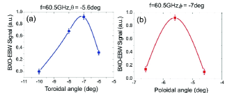
These scans also led to the identification of the conditions for strongest emission and, by reciprocity, for successful EBW heating of MAST Shevchenko et al. (2007). The results of Fig.1 motivated the development of a fast steering antenna in order to, respectively,
-
1.
reconstruct the conversion efficiency contours as functions of the view angles and, from their shape and inclination, infer the magnetic pitch angle at the OX conversion location, i.e. at the O-mode cutoff layer for a certain frequency . Simultaneous and/or scanning measurements at various f provide the pitch angle at various radii, i.e., ultimately, the profile,
-
2.
quickly assess the optimum conditions for heating within a single discharge.
The present paper presents the fast steering antenna (Sec.2) and the first experimental results (Sec.3).
II Self-balanced Spinning Mirror
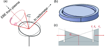
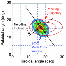
Consider a rotating mirror tilted around the axis of rotation as in Fig.2a. This reflects into a radiometer horn a line-of-sight that changes with time. Three mirrors were developed, with tilt angles =1.5, 3 and 4.5o, capable of horizontal scans of and vertical scans of . Correspondingly, the line of sight describes the elliptical trajectories marked in red in the angular space of Fig.3. Before a discharge, pre-alignment of the diagnostic sets the center of the angular scan; selecting a mirror of one tilt or another determines the width of the scan. The choice depends on the type of discharge (e.g. L-mode or H-mode) and the corresponding expected conversion efficiency contours (narrow or broad, respectively). Good pre-settings allow to sample the conversion efficiency contours during (a fraction of) the angular scan. In particular it is desirable to cross in two points at least one of the axes of symmetry of these elliptical contours, so that their inclination can be determined.
The simplistic, unbalanced setup of Fig.2a would be subject to forces trying to flatten the mirror and annihilate the tilt. To compensate for these forces, a rotor is manufactured as a single block featuring a central reflector surrounded by a counter-balancing ring of equal and opposite inclination, as in Figs.2b-c. The ring thickness, , is related to the central reflector radius by the simple relation so that centrifugal forces of 3.3585 tonnes acting on one half of the rotor at 12,000rpm are compensated by equal and opposite forces acting on the other half.
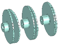
In an alternative design (Fig.4) the counter-balancing element lies behind the actual mirror, not around it. This, however, would be subject to higher orders of vibration. Hence, the design of Fig.2c was adopted.
The material adopted, glass-fiber-reinforced Nylon 66, avoids magnetic braking and other eddy current effects and withstands the high mechanical stresses involved. It also has relatively low density, which reduces the centrifugal forces. The diagnostic support was carefully designed and modeled to avoid mechanical resonances at the frequencies of interest (100-200Hz). Vibrations, already reduced by the special design, were further minimized with the help of a balancing machine. As a result, excellent balancing was demonstrated, with forces as little as 1N even at full speed (12,000rpm) and for the steepest (4.5o), thus, potentially most unbalanced spinning mirror. Note that, due to centrifugal forces, the shape of the rotor changes with speed. As a result, optimal balancing for a certain speed is not necessarily optimal at other velocities, including lower speeds.
The Nylon substrate was successfully polished (despite the difficulties associated with the glass fibers embedded in it) or coated with gold. However, coating on the polished material tended to peel off. For this reason, a layer of gold as thick as 3 skin depths was deposited on a 2mm polished polycarbonate plate and this was glued with strong epoxy on the Nylon, which was re-balanced. Each mirror was mounted on a shaft held by a matched pair of ball bearings and by a cylindrical roller bearing in a spindle housing. Three such “units” were prepared, with mirrors inclined by 1.5, 3 and 4.5o. A 3-phase induction motor drives the shaft. The motor and the shaft are not coupled rigidly, but by pulleys and a flat belt. Units can be substituted before a plasma discharge, depending on the desired angular scan width. The orientation of the mirror is measured with 1o precision by an optical encoder.
III Experimental Results
The manual, shot-by-shot angular scans of Fig.1 were performed with a 12 channel, 54-66GHz radiometer connected to the 60GHz EBW heating antenna, whose steering mirrors are on the vacuum side.
The new fast steering antenna, however, has been installed outside the torus, in front of the main EBW emission diagnostic.
The spinning mirror reflects the EBW emission exiting from the torus flange onto a flat mirror and this in a horn antenna and a Teflon lens optimized for 40GHz that refocuses the beam and limits its divergence to less than 3o. All this Gaussian optics is located 20cm below the plasma mid-plane. Directional couplers split the signal between three scanning radiometers (16-26, 26-40 and 40-60GHz), here operated at fixed frequencies, and a bank of 11 fixed channels (6-18GHz). The measurements presented here were carried out with the 4.5o spinning mirror in the 10-36 GHz range. These frequencies correspond to emission at the first and second harmonic and to OX conversion at locations where -, i.e. at the plasma edge.
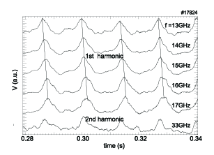
Fig.5 shows the first angular scans of EBW emission realized with the spinning mirror within a single discharge. Although optimized for 12,000rpm, for this initial test the mirror was rotated at 4400rpm, yielding a complete angular scan for each channel every 13.6ms. As expected, different channels reach their maximum at different times, i.e. for different view angles. This is consistent with the emission at different frequencies undergoing the final XO conversion at distinct cutoff layers, lying at different depths in the plasma, where they pick up the information on the local pitch angle. As the local pitch angle changes from channel to channel, the optimal direction also changes, and the best alignment is obtained at different times. The trend is consistent for all channels looking at the 1st harmonic, then the time-delay is “reset” in the transition to the 2nd harmonic, consistently with the fact that the emission is suddenly originating in an outer position.
Additional effects contribute to the time-modulation of the signal and need to be minimized or deconvolved:
-
•
incomplete shine-through of the microwave beam, slightly broader and thus partly masked by the port, especially at low frequencies,
-
•
stray radiation reaching the antenna after multiple reflections in the vessel,
-
•
changes of the Doppler shift with the view angle. As a result, the EBW emitting layers move radially by a few centimeters during the scan. The resulting oscillation of the radiative temperature, however, amounts to a few percent, and is dwarfed by the change in conversion efficiency, which can oscillate by as much as 100%.
However, these effects alone would cause all channels to oscillate with the same phase. Time-shifts from channel to channel, as observed in Fig.5, are considered a signature of genuine angular scan of BXO-converted EBW emission at different frequencies.
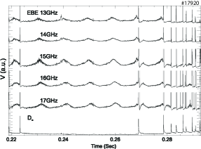
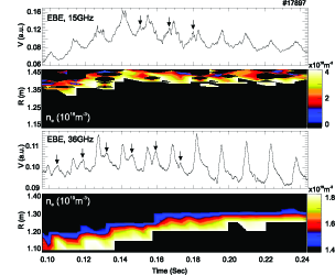
The data in question oscillate at the rotation frequency of the mirror, suggesting that they cross the conversion efficiency contours once per revolution. Hints of a second peak are visible in Fig.5 but become more evident in another discharge, in Fig.6, with a steeper density gradient and a broad enough conversion efficiency window for the angular scan to cross its axis twice. Time intervals with two maxima are good candidates for inferring the inclination of the conversion efficiency contours and thus, ultimately, the magnetic pitch angle. The analysis is in progress. The mode-converted emission appears to correlate with edge localized modes (ELMs) (Fig.7). Like Electron Cyclotron Emission, pure EBW emission is expected indeed to be correlated with ELMs. The mode conversion, instead, becomes less efficient during an ELM, due to the reduced density gradient. In other words, ELMs enhance EBW emission but reduce BXO transmission. The signals are the product of these two quantities. Note that emission doesn’t depend strongly on the view angles, while transmission does. Note also that a pitch angle measurement needs a complete angular scan, and this is only possible if the inter-ELM period is sufficiently long, as for =0.225-0.265s in Fig.7.
IV Summary and Conclusions
In conclusion a technique for measuring the profile was proposed, based on anisotropy of the BXO mode conversion and a tilted spinning mirror of special self-balanced design was installed on MAST for this purpose: by completing an angular scan of EBW emission every 2.5-10ms, the spinning mirror allows to characterize with good time resolution the BXO conversion efficiency as a function of the view angles. This decays anisotropically as the line of sight departs from an optimal direction. In first approximation the direction of steepest descent gives the local magnetic field. In presence of magnetic shear, however, the contours deform Cairns and Lashmore-Davies (2000) and a more sophisticated analysis involving a full-wave code would become necessary. The device was described, with emphasis on the materials and design. The first angular scan results exhibit the expected shape, frequency dependence and ELM dependence.
Acknowledgements.
This work was funded jointly by the United Kingdom Engineering and Physical Sciences Research Council and by the European Communities under the contract of Association between EURATOM and CCFE. The views and opinions expressed herein do not necessarily reflect those of the European Commission.References
- Soltwisch (1992) H. Soltwisch, Plasma Phys. Control. Fusion 34, 1669 (1992).
- Donné (2002) A. J. H. Donné, Plasma Phys. Control. Fusion 44, B137 (2002).
- Levinton (1999) F. M. Levinton, Rev. Sci. Instrum. 70, 810 (1999).
- Rice et al. (1999) B. W. Rice, D. G. Nilson, K. H. Burrell, and L. L. Lao, Rev. Sci. Instrum. 70, 815 (1999).
- Thomas et al. (2004) D. M. Thomas, A. W. Leonard, L. L. Lao, T. H. Osborne, H. W. Mueller, and D. F. Finkenthal, Phys. Rev. Lett. 93, 065003 (2004).
- Thomas (2003) D. M. Thomas, Rev. Sci. Instrum. 74, 1541 (2003).
- Hallock et al. (1986) G. A. Hallock, J. Mathew, W. C. Jennings, R. L. Hickok, A. J. Wootton, and R. C. Isler, Phys. Rev. Lett. 56, 1248 (1986).
- Soltwisch (1988) H. Soltwisch, Rev. Sci. Instrum. 59, 1599 (1988).
- Tritz et al. (2003) K. Tritz, R. Fonck, M. Reinke, and G. Winz, Rev. Sci. Instrum. 74, 2161 (2003).
- Laqua (2007) H. Laqua, Plasma Phys. Control. Fusion 49, R1 (2007).
- Mjølhus (1984) E. Mjølhus, J. Plasma Phys. 31, 7 (1984).
- Laqua et al. (1997) H. Laqua et al., Phys. Rev. Lett. 78, 3467 (1997).
- Laqua et al. (1998) H. Laqua et al., Phys. Rev. Lett. 81, 2060 (1998).
- Cairns and Lashmore-Davies (2000) R. Cairns and C. Lashmore-Davies, Plasma Phys. 7, 4126 (2000).
- Shevchenko et al. (2007) V. Shevchenko et al., Fusion Sci. Technol. 52, 202 (2007).