An einzel lens with a diagonal-slit central electrode to combine steering and focusing of a low energy ion beam
Abstract
In many applications of the simple three-element einzel lens, such as injecting a low energy ion beam into a high-field Penning trap, there is a need for small-angle steering as well as focusing of the beam. We have analyzed a diagonal-slit cylinder serving as the middle electrode of such a lens and have shown that such an electrode configuration significantly diminishes the aberration associated with such a deflection.
keywords:
Einzel lens , Einzel lens deflector combination, Einzel lens aberrations, EmittancePACS:
41.85.Ne, 41.85.-p, 42.15.Fr1 Introduction
The einzel lens, consisting of a single activated cylindrical electrode centered between two cylindrical electrodes at ground [1], is a particularly useful electrostatic lens for low energy ion beams. This is because it is simple, compact and azimuthally symmetric. It is particularly useful for applications such as the injection of a low energy ion beam into a high magnetic field Penning trap, where a compact system is needed for focusing a low energy ion beam onto the azimuthally symmetric magnetic field lines of the trap [2].
However, it is difficult, in general, to produce the azimuthally symmetric focussing quadrupole field in an einzel lens without strong components of higher order multipoles. Most significant of these is the azimuthally symmetric octupole which results in spherical aberration. Many studies of this aberration have been carried out, one of the most thorough being Ref. [3]. As a result of this aberration only about a quarter of the internal diameter of the central electrode of a simple einzel lens is useful if the emittance of a typical low-energy ion beam is not to be significantly increased. This means that an einzel lens has to be considerably larger than the beam it has to focus, making it less compact than desired.
This problem is compounded when the beam has to be steered as well as focused, as is necessary for injection into a Penning trap. This is because any misalignment of the ion trajectories with the magnetic field lines of the trap results in cyclotron motion that becomes amplified as the ions enter the high field of the trap, interfering with the use of the Penning trap as a mass measuring device. The enlargement of the einzel lens to accommodate its spherical aberration leaves little room for separate electrostatic steering electrodes. It is therefore desirable to combine the steering and focusing functions in the single central electrode of the einzel lens.
However, the introduction of a steering field by simply segmenting the central electrode of an einzel lens can also bring with it an aberrant field that can itself distort the emittance diagram at the beam focus. This paper describes a means of reducing that aberrant field.
2 The aberration of a central steering field of an einzel lens
Parallel plate electrodes replacing the middle cylinder in an einzel lens, may be used to combine the deflecting field with the focusing filed. Since there is no azimuthal symmetry in the focusing field, such a design is useless for practical purposes. However, the design can be modified by placing another set of parallel plates, thus forming a box at the middle. Such a configuration, to a close approximation, produces an azimuthally symmetric quadrupolar potential required for focussing. Each of the four plates may be activated independently with different potentials in order to achieve bending in any direction. However, the deflecting field of a box electrode would be highly non-linear, being much stronger in the direction of steering on the axis of the lens than near the surfaces of the electrodes that are parallel to the steering direction. Thus the design of such a system is not desirable when an ion beam of a given emittance is required to be steered by sufficiently larger angle while being tightly focused.
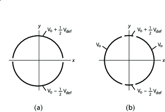
Another possible way to introduce the deflecting field with the focusing field is to make a parallel slit in the middle cylinder in an einzel lens as it is shown in fig. 1a. The deflecting field in this design will increase along the slit axis perpendicular to the direction of propagation resulting in significant sextupole distortion. The design may be improved to minimize the distortion by slitting the central cylinder into four segments as shown in fig. 1b. It thus suggests that there should be sector segmentations if it is required to steer the ion beam in any arbitrary direction and the design of such a system will be complicated.
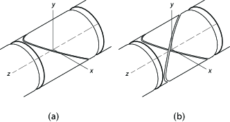
Here we show that an einzel lens with the middle cylinder having a diagonal slit as shown in fig. 2a, is the best solution to this problem. The design allows comparatively larger steering and focussing of an ion beam within acceptable aberration. The cylinder may have another diagonal slit perpendicular the first one (as in fig. 2b) so as to achieve the steering along any direction on the focal plane. Ref. [4] introduces such a configuration on its first implementation at the SHIPTRAP [5] facility at GSI and it is in use also at TITAN facility TRIUMF [6]. Here we have studied the design thoroughly and compared it with a parallel-slit configuration. At the end we show that a diagonal-slit is the best choice compared to other design in view of the maximum extent of the deflection angle that it allows to focus a low energy ion beam without significant aberration.
3 Simulation results and discussions
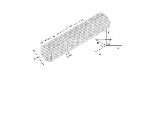
In order to evaluate the deflection aberration of a diagonal cut einzel lens we have taken a typical lens geometry shown in fig. 3. This einzel lens has a middle electrode of length mm, inner diameter mm and two identical electrodes at each end of length and inner diameter mm. The middle cylinder is separated by a distance mm from each end cylinder. Beam focusing is achieved by elevating the potential of the middle electrode (for positive ions) while keeping the end electrodes at ground.
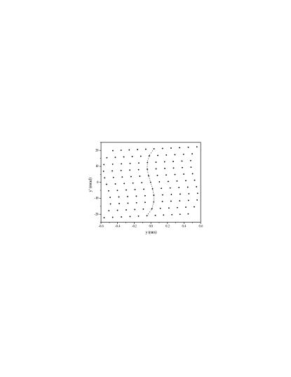
A representative beam has been taken to study the performance of different ion optical systems. Each ion has a mass amu, positive charge of one electron unit and a kinetic energy of eV. The array of ions start at mm from the center of the lens ( mm before the entrance to the first ground electrode). They are initially spaced symmetrically about within mm along axis, in steps of mm with their divergence () symmetrically spaced about within mrad, in steps of mrad. Thus the beam initially forms a square array of by points with ions in the emittance diagram having an emittance area of mm mrad. Each ion in this diagram has neither displacement nor divergence distribution (i.e. mm, ). The trajectory of the ion beam has been simulated using SIMION D , including the grounded vacuum enclosure of the lens assembly. The potential at the middle electrode is then varied until the array is focused at a desired distance from the lens assembly. In our simulation the focus is set at an axial distance of mm from the lens center ( mm from the lens exit) when the central electrode in fig. 3 is elevated at potential of V. The emittance diagrams at the focus are examined for aberrations and the size of the emittance arrays adjusted until the spherical aberration is regarded as acceptable. This is found to be the case with the emittance array described earlier. The resulting emittance diagram at the focus is shown in fig. 4. This clearly shows the “S” shaped distortion due to the octupole aberration but that is regarded as acceptable since it doesn’t significantly increase the effective area of the emittance diagram.
Because of the azimuthal symmetry of an einzel lens the emittance diagram at the focus is, of course, identical to fig. 4.
Now with the same initial beam emittance, we have studied the effect of combining the deflecting field with the focusing field. The middle cylinder in the einzel lens is slit in parallel along the plane into two halves and each of them is activated independently with different voltages so as to achieve the steering along direction. A potential difference of V about V focusing potential is applied between the middle electrodes in order to obtain a steering angle of mrad of the same representative beam. The emittance diagram at the focus is shown in fig. 5 which shows a large “U” shaped distortion representing a clear signature of an unacceptable sextupole aberration.
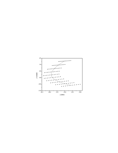
The central cylinder of the einzel lens is segmented by a diagonal cut as in fig. 3. The potential difference between the two segments is adjusted so as to achieve the same bending of mrad as for the parallel-slit electrode. This is achieved with a potential difference of V (as compared to the V required for the parallel segmented electrode, due to the smaller dipole field of the diagonally segmented electrode.) The resulting emittance diagram at the focus is shown in fig. 6a. The signature of the deflection field aberration is barely detectable in this figure. In order to make it prominent, another simulation has been performed for a deflection potential of V resulting in a steering by mrad. The emittance diagram is presented in fig. 6b. Fig. 6a and fig. 6b thus represent a qualitative comparison of the sextupole distortion in the emittance diagram and hence the aberration as a function of the deflecting potential or the steering angle.
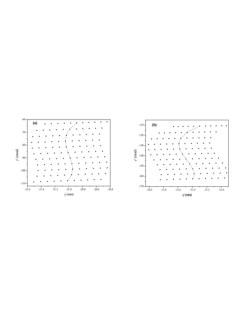
Fig. 5 and fig. 6a present a comparative performance between a parallel-slit and a diagonal-slit configurations of same dimensions for a given angle of steering of a low energy ion beam. For diagonal-slit deflector, the ions are converged within mm (fig. 6a) while for the parallel-slit deflector they spread over a region of mm (fig. 5) along the axis of steering. These two figures thus naturally inspire to choose a diagonal-slit configuration as the best compact low energy ion beam deflector-lens.
In order to realize the reason behind the better performance of a diagonal-slit rather than a parallel-slit configuration, the azimuthal symmetry associated with these two configurations should be considered. The distortion for the deflecting field in the middle electrodes changes in the axial direction for a diagonal-slit deflector while it is constant for a parallel-slit design. At the entrance and exit of the diagonal-slit deflector, the deflecting field has a curvature such that the field is diminished with the distance along the axis in the direction perpendicular to the field. The field curvatures are in opposite directions relative to the center of the middle electrodes and therefore there occurs a cancelation of the distortion. The cancelation, however will not be perfect since the opposite deviations occur in separate regions of the beam and may not be equal. They only tend to cancel each other because the beam does not change much as it passes through the central electrode, the degree of cancelation being determined by the length to diameter ratio of the middle electrode and the initial transverse emittance of the ion beam. At the center of the electrode a strong deflecting field exists along which direction the beam is to be steered. The solution of Laplace’s equation inside the deflector-lens system can be represented as
| (1) |
where indicates the strength of multipole and is the Legendre polynomial of . The ions are focused due to the azimuthally symmetric quadrupole component (, ) of this potential in case of an einzel lens. They are deflected due to the dipole component (, ) for a deflector. Several higher order multipoles contribute significantly in any practical ion-optic system resulting in different order of aberrations. The first order aberration arises from the azimuthally symmetric octupole part (, ) in an einzel lens and the next higher order contribution arises from the sextupole component corresponding to , for a diagonal-slit deflector. Considering these four components of the potential, the transverse components of the electric field at the middle () of a real diagonal-slit deflector-lens (for steering along ) are given by
| (2) |
and
| (3) |
In presence of the electric field in Eqn. 2, the divergence () of an ion beam having initial initially, is approximately represented as a function of their instantaneous position at the center () of the deflector-lens in the following way
| (4) |
where , , , are proportional to , , and respectively. When a parallel beam ( initially) of ions having only initial distribution symmetric about , is allowed to pass through the diagonal-slit deflector, the emittance of the beam follows Eqn. 4. The emittance of the beam is observed at the center of the diagonal-slit deflector-lens for a deflecting potential V and it is shown in fig. 7. The plot is fitted with the Eqn. 4 with , , , . It shows that the magnitude of the coefficients of successive higher order multipoles gradually decreases but their contributions are more dominating near the surface of the electrodes.


However, as the beam propagates through the system and is converged, the emittance plot at the focus takes the shape as it is shown by dotted line in fig. 6b. In case of an einzel lens the first and third terms in Eqn. 4 are absent and hence the emittance diagram shows only an “S” shaped distortion at the focus as represented in fig. 4. Since the coefficient is proportional to the deflecting potential, the distortion due to the sextupole component increases almost linearly with increasing deflecting potential.
Eqn. 3 predicts that a representative beam having only emittance and initially, experiences a distortion only due to the octupole component and the deflecting potential has no effect in the emittance diagram. This point has also been checked in our simulation. Fig. 8 shows the emittance diagram at the focus of the diagonal-slit deflector-lens with deflecting potential V for this representative beam. It does not show any significant difference as compared to fig. 4. A small deviation is the consequence of the contribution of higher order multipoles of little interest and beyond the scope of this study.
4 Conclusion
A novel system has been described for using the central electrode of a simple einzel lens for both steering and focusing a low energy ion beam with minimal aberrations. It involves cutting the central electrode in planes that pass through the lens center and are orthogonal to each other but that are tilted to the lens axis. The position of the focus and the steering angle in any direction can then both be controlled by adjusting potentials on the middle electrodes. The system is very useful to handle a steering of the order of degrees or less. Furthermore, since and coordinates are independent, two diagonal cuts at degrees azimuth to each other (fig. 2b), can be used to steer the beam in any arbitrary direction.
Acknowledgments The authors sincerely thank Prof. R. B. Moore, McGill University, Montreal, Canada for his useful suggestions at different stages of this work and for his assistance in drafting of this manuscript. P. Mandal is thankful to the Council of Scientific and Industrial Research (CSIR), India for sponsoring the fellowship during the research work.
References
- [1] A. Adams, F. H. Read, J. Phys. E: Sc. Instrum., 5 (1972) 150
- [2] M. Mukherjee, D. Beck, K. Blaum, G. Bollen et al., Eur. phys. J., A 35 (2008) 1
- [3] G. Rempfer, J. Appl. Phys., 57 (1985) 2385
- [4] G. Sikler, PhD Dissertation , University of Hiddleberg, 2003
- [5] M. Block, D. Ackermann, K. Blaum et al., Eur. Phys. J., D 45 (2007) 39
- [6] D. Dale, R. Nussbaumer, T. Howland et al., Proceedings of ICALEPCS07, Knoxville, Tennessee, USA