An ab initio design of cluster-assembled silicon nanotubes
Abstract
Density functional calculations were performed to systematically study a series of finite and infinite cluster-assembled silicon nanotubes (SiNTs). One-dimensional SiNTs can be prepared by proper assembly of hydrogenated cage-like silicon clusters to form semiconductors with a large band gap, and their electronic properties can be accurately tuned by transition metal doping in the center of the tubes. Specifically, doping with Fe made the SiNTs metallic and magnetic materials. More interestingly, a metal to half-metal transition was observed with increasing tube radius in Fe-doped SiNTs, which demonstrates that SiNTs doped with magnetic elements may find important applications in spintronics.
Keywords: Hydrogenated silicon clusters, HOMO-LUMO gap order, cluster-assembled nanotube, magnetic properties, metal half-metal transition
pacs:
73.22.-f, 36.40.Cg, 61.46.Fg, 75.75.+aI INTRODUCTION
Since the discovery and application of carbon fullerenes and carbon nanotubes(CNTs) fullerene , stable cage and tube-like structures have attracted a great deal of attention. These structures have generated great interest in creating analogous structures from other elements that are suitable for applications in nanodevices. Silicon and carbon are members of the same group in the periodic table, suggesting a potential ability to form similar structures. Furthermore, due to the fundamental importance of silicon in present-day integrated circuits, substantial efforts have focused on investigating nano-scale forms of silicon, both for the purpose of further miniaturizing the current microelectronic devices and in the hopes of unveiling new properties that often arise at the nano-scale levelJPCM_16_1373 . However, it is difficult to form cages or tubes like carbon fullerenes or nanotubes purely with Si atoms because silicon does not favor the 2 hybridization that carbon does. Carbon normally forms strong bonds through hybridization, which can facilitate the formation of two-dimensional spherical cages (or planar structures such as benzene and graphene). Silicon, on the other hand, usually forms covalent bonds through hybridization, which favor a three dimensional diamond-like structure.
Fortunately, Si cage clusters can be synthesized by adding suitable foreign atoms to terminate the dangling Si bonds that inherently arise in cage-like networks. Many researchersjctn257 ; cms1 ; prb195417 reported that transition metal(TM) atoms are the most suitable element for cage formation due to their band features. In addition, rare earth atoms have been doped into silicon cagesjcp084711 ; epjd343 ; prb125411 ; prb115429 . Another way to stabilize the Si cage is to use hydrogens to terminate the cluster surfaceprb075402 ; prb155425 , which is similar to the dodecahedral C20H20.
Several hollow and nonhollow silicon nanotube structures have been proposed and theoretically characterized in recent years pnas2664 ; jmst127 ; prl265502 ; nl301 ; nl1243 ; nano109 ; jmc555 ; njp78 ; prl146802 ; cpl81 ; prb075420 ; prb195426 ; jpcb7577 ; jpcb8605 ; prb9994 ; jpcc5598 ; prb11593 ; prb205315 ; prb075328 ; ss257 ; prb193409 ; jpcc16840 ; prl1958 ; pssr7 ; prb155432 ; prl792 ; jpcc1234 . These structures, which were proposed based on intuition or the behavior of similar materials, include the following:
(1) Regular polyhedron stacking nanotubes pnas2664 ,
(2) Surface capped polygonal prism stacking nanotubes jmst127 ,
(3) Polycrystalline forms of nanowires prl265502 ,
(4) Metal encapsulated polygonal prism nanotubes nl301 ; nl1243 ; nano109 ; jmc555 ; njp78 ; prl146802 ,
(5) Carbon nanotube like structures cpl81 ; prb075420 ; prb195426 ; jpcb7577 ; jpcb8605 ; prb9994 ; jpcc5598 ,
(7) Metal centered fullerene-based structures prb075328 ,
In the cases of (1), (3), (5) and (6), similar to pure silicon cages, it was reported to be difficult to form hollow single wall Si nanotubes because of the nature of Si atom. Cases (4) and (7) proposed that metal doping may be a good way to terminate the dangling bond of silicon bond in the tube, but this approach was limited to tubes with very small radii(1nm).
However, if the lateral surfaces of the dangling bonds are terminated by hydrogens, the resulting cage-like silicon clusters may be perfect building blocks for Si nanotubes. Theoretically, every Si atom has three neighboring Si atoms in the nanotube, and these have an 3 type bond nature with one H terminating the dangling bond. Moreover, the success of this approach is suggested by the fact that in experiments, the surfaces of Silicon nanowires(SiNWs) and silicon nanotubes(SiNTs) are always passivated by hydrogen atoms science1874 ; jpcb8605 or by silicon oxide layers am1219 ; am1172 ; am564 ; prl116102 .
This work presents a theoretical study of hydrogenated cluster assembled silicon nanotubes using density functional theory(DFT) calculation. A series of finite and infinite silicon nanotubes assembled by hydrogenated cage-like clusters was obtained. Additionally, the electronic and magnetic properties of SiNTs can be accurately tuned by doping impurities at the center of the hollow tube. One interesting result was that a metal to half-metal transition was observed in Fe-doped SiNTs with the increasing of tube radius.
II COMPUTATIONAL DETAILS AND MODEL DESIGN
All theoretical computations were performed with the DFT approach implemented in the Dmol3 package jcp92 ; jcp113 , using all electron treatment and the double numerical basis including the -polarization function(DNP)jcp92 . The exchange-correlation interaction was treated within the generalized gradient approximation(GGA) using BLYP functional. Self-consistent field calculations were performed with a convergence criterion of 210-5 Hartree on total energy.
The (=16, 20, 24, 28, 32) clusters were optimized first, and some of the initial structures in our work were based on the results reported in Refs. prb075402, & prb155425, . After obtaining stable single clusters, we took these clusters as basic units (keep them as original) and stacked the clusters with a certain along the axis of symmetry to construct finite nanotubes.
For infinite one dimensional nanotubes, the periodically repeated units were placed in supercells. The supercell is cubic in geometry with the dimensions 25Å25Åz, where the direction of z was defined as the axial direction of the nanotubes. Periodic boundary conditions were employed along the nanowire axis to create, in effect, continuous wires. Meanwhile, a sufficiently large vacuum region was introduced along the other directions is configured between the wires.
III RESULTS AND DISCUSSIONS
III.1 Structures of clusters and finite nanotubes
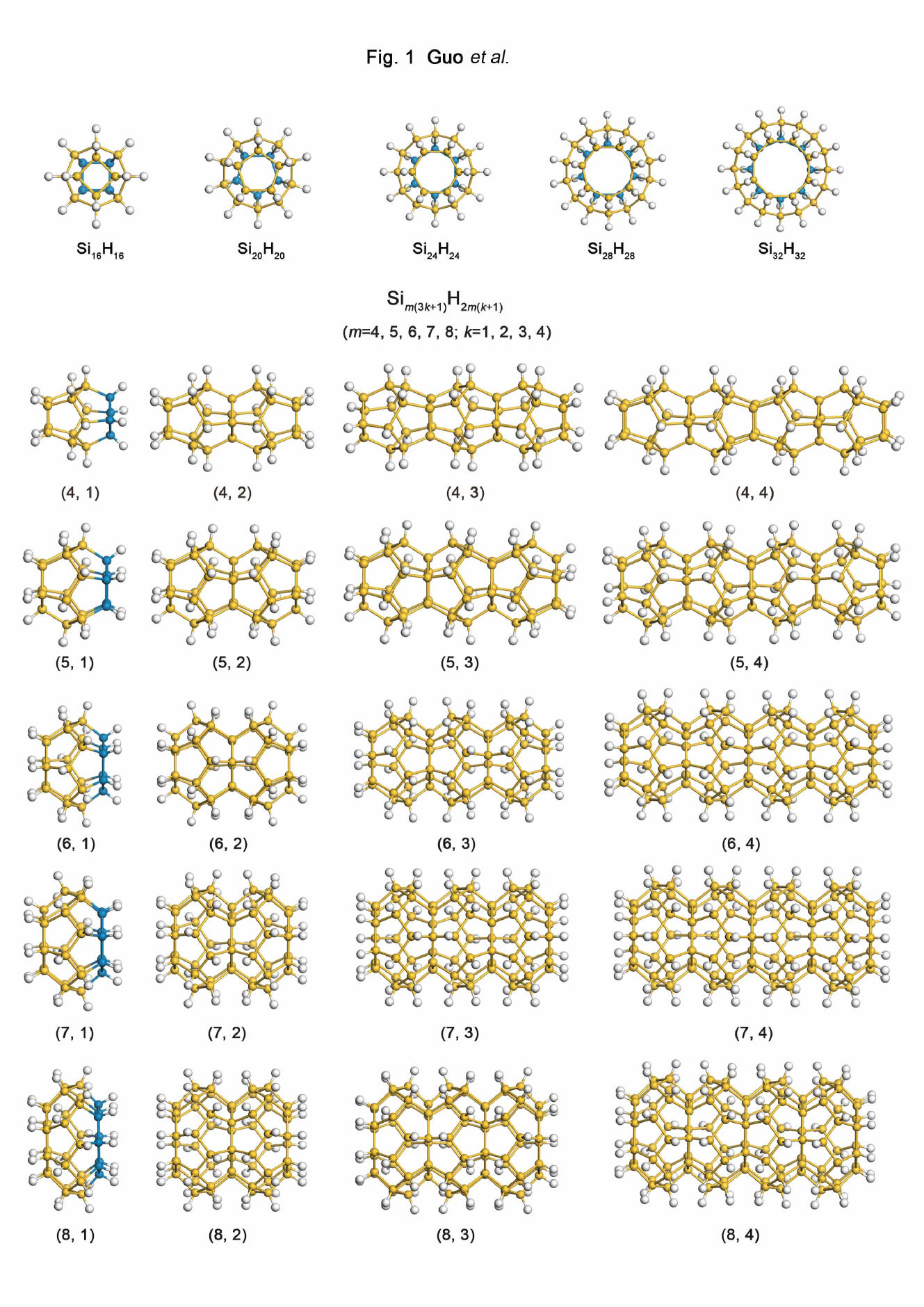
The fully optimized structures of (=16, 20, 24, 28, 32) clusters that have been fully optimized are shown in Fig. 1. It was very interesting to see that all these structures shared the following common characteristics: 1. All of them were fullerene-like hollow structures. 2. Each Si atom had three Si neighbors, with one H atom saturating the dangling bond of each silicon atom outside the cage to fulfill an type hybridization bond. 3. All structures consisted of pentagons and two other polyhedrons at the two ends, with the edge number of these two polyhedrons as . Meanwhile, these two polyhedrons were parallel to each other and there was a relative angle of between them. Thus each vertex atom of one polyhedron fell exactly in the middle of one edge in the other polyhedron. Specifically, for , the cage was composed of 12 pentagons, which was very similar to the structure of carbon fullerene . Structures of , and have been widely discussed in very recent years prb075402 ; prb155425 and the structural information we obtained was consistent with these reports.
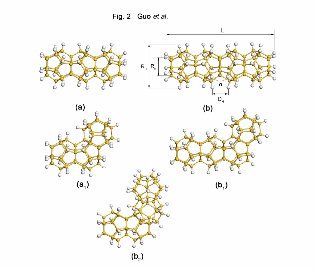
Taking these original clusters original as basic units, we stacked them along the central axis of the cage to form finite nanotubes. The two adjacent cages shared the same polyhedron. We noted that for the shared polyhedron, there was no need for have hydrogen saturation because each Si atom already had 4 Si neighbors and thus the hybridization bond type was fulfilled. The molecular formula of the finite tube was classified as , where the measure of radius was the number of atoms of one shared polyhedron and the measure of length was the number of repeated units. After full optimization, for one certain value (=4, 5, 6, 7), and for range from 2 to 4 concerned in the present work, the tube was always straight and stable. Furthermore, if the number of repeated units was fixed, the length of the tubes decreased with the increasing . The angles of H-Si-Si and Si-Si-Si inside the repeated units were all about 109∘, which were very close to the 109.5∘ of , but the Si-Si-Si angle (angle in Fig. 2 (b)) between two units became smaller and smaller with the increasing of tube radii (from 127.8∘ of =4 to 99.0∘ of =8).
Even though, the growth direction and the achievable length of the nanotubes are the main experimental concerns, previous theoretical studies have paid little attention to these issues. Here, we chose nanotubes to examine if straight tubes were more stable than bent nanotubes. As shown in Fig. 2, (=5, =3)(Fig. 2 (a)) had an isomer (a1) (Fig. 2 ()) that was bent to 120∘ from 180∘, but the total energy (ET) of () was 0.02eV higher than that of the straight tube (). Likewise, (=5, =4) has two isomers (Fig. 2 ()) and (Fig. 2()), where the structure was a tube in which the unit at the end was bent, and structure was distorted further. These isomers were less stable because the total energy of () was higher than that of the linear structure by 0.021 or 0.034, respectively. For hydrogenate silicon tubes, if one tube was bent by an angle, the distance between H atoms of adjacent units would decrease and the Coulomb repulsion between them would makes the total energy greater than the straight energy. Consequently, the linear structure was relatively more stable than bent structures.
III.2 ELECTRONIC STRUCTURES
In order to measure the relative stability of the tubes as well as the influence of the length and width, we calculated the averaged binding energy () and dissociation energies () of these tubes. The and DE for finite tubes were defined by the following formulae:
| (1) |
| (2) |
where , , and [] represent the total energies of the Si atom, H atom, SiH dimer and the tube, respectively.
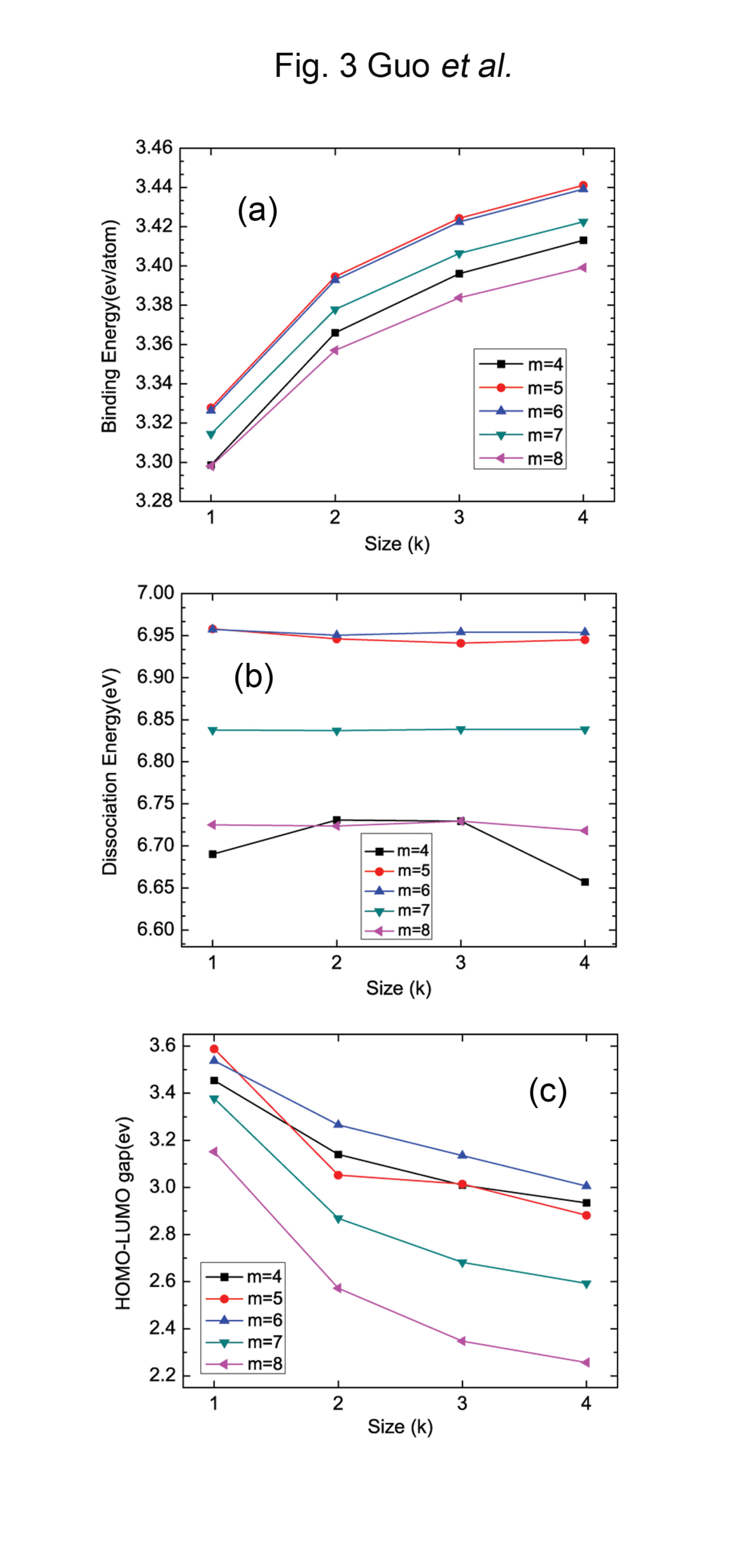
As illustrated in Fig. 3 (a), the binding energy of the finite tube increases gradually as the length increased for a certain . This correlation indicates that the tube became increasingly stable as it became longer. On the other hand, the stability of the tubes did not depend linearly on the tube’s radius, which was represented by . For any , the most stable tubes were at =5 or =6.
DE is the energy needed to remove a Si-H dimer from the end of a tube, and this parameter provided another method to probe the tube stability. The curves of DE (Fig. 3 (b)) indicate that it was more difficult to remove a Si-H dimer from the tubes with =5 and 6 because these two specific tubes satisfied hybridization well. This is another indication of the fact that tubes with =5 or 6 are the most stable.
In addition, Fig. 3 (c) plots the variation of the highest occupied molecular orbital (HOMO) and lowest unoccupied molecular orbital (LUMO) gaps of the finite tubes. The quantum confinement concept demands a larger gap for a smaller size. The authors in Ref. prb075402, ever argued that the quantum confinement concept was not fully applicable to saturated systems such as cages. Our work also provides evidence on the limitation of the quantum confinement concept in interpreting the gaps of hydrogenated silicon nanotubes.
As seen in Fig. 3 (c), when is fixed, the gaps between HOMO-LUMO became smaller with increasing length. However, there was a big jump in the gap from a single cluster to a two-unit tube. This difference could come from a hybrid bond around the Sim cylinder joints which was different from the fully hydrogenated silicon atoms in a single cluster. Moreover, the Coulomb repulsion between hydrogen atoms of an adjacent unit could play a role in defining gaps, as explained below.
The tubes of , and had similar HOMO-LUMO gaps due to analogous structural parameters including bond angle, length and width. The gaps of larger radii tubes and tubes were much smaller than those of the smaller radii tubes , and . Similar to Ref. prb075402, , we estimated the effective volume per electron by drawing two concentric cylinders with and in Fig. 2 (b) up to the layer of hydrogen and silicon.
The was defined as:
| (3) |
where was the number of electron and was the length of the cylinder (Fig. 2 (b)).
is the measures of electron ”confinement”, which would lead to the same order of gap performance according to the quantum confinement concept. Hence, in our work, the order of effective volume per electron of [=7] [=6] [=8] [=4] [=5], as in Table 1, would have resulted in a HOMO-LUMO gap order of [=7] [=6] [=8] [=4] [=5]. However, as shown in Fig. 3(c) and Table 1, the HOMO-LUMO gap order was [=6] [=4] [=5] [=7] [=8]. The HOMO-LUMO gap order only followed the rule of quantum confinement for small radii tubes(=4, 5, 6). The limitation of quantum confinement for large radii tubes (=7, 8) may arise from the fact that these tubes have a smaller distance between the H-H bonds of neighboring units( in Fig. 2 (b)). For example, of 4.206Å for =4 compared to that of 2.723Å or 2.567Å for =7 or 8. That is to say, for one-dimensional finite hydrogenated silicon nanotubes, quantum confinement only worked for small radii tubes.
To summarize, in addition to the quantum confinement, the effects of suitable bond angle( in Fig. 2 (b)), and Coulomb repulsion between H atoms also played important roles in affecting the HOMO-LUMO gaps of systems.
III.3 INFINITE TUBES
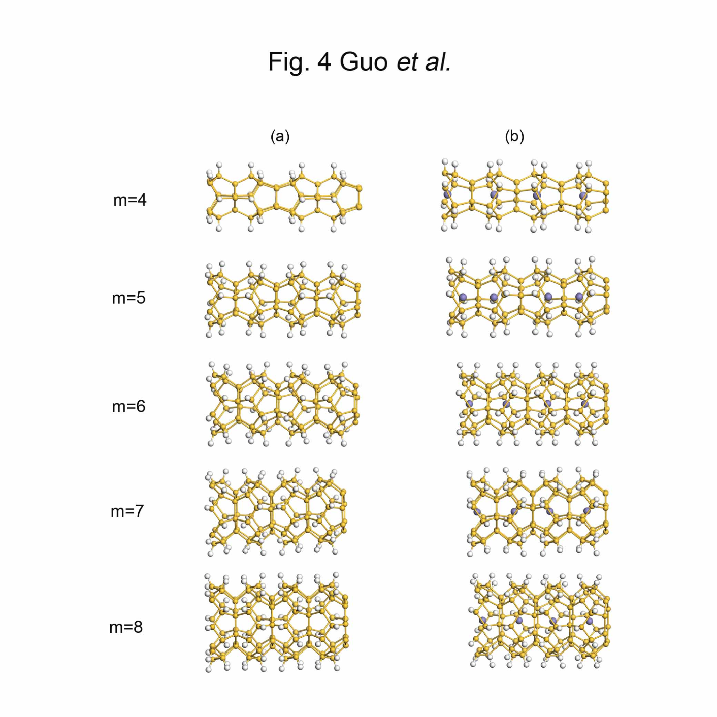
The increased stability of finite nanotubes with an increasing number of units allowed us to examine further the stability of the infinite nanotubes specifical with a stoichiometric . This infinite tube was built from finite by removing a on one side and H atoms on the other side to form a repeated unit. Fig. 4 shows two repeated cells of the infinite tubes with different radii. All of these tubes had the stacking of SiH cages in common, with the wire axis lying in the center. The axis passed through the centers of buckled rings, and two adjacent cages shared one ring.
Full structure relaxation indicated that the infinite nanotubes had similar geometric structures to finite ones, but the tube lengths had slightly changed. The lenths of and tubes became 0.08Å and 0.11Å longer than the finite ones, but for , and the lengths became 0.075Å, 0.212Å and 0.365Å shorter. The tube widths and Si-H bond lengths were almost the same as for the finite ones.
The binding energies of the infinite tube shown in Table 2 were slightly larger than those of finite tubes, which meant that it was possible to synthesize tubes long enough. The silicon tube had a relatively large band gap() (2.296eV-3.009eV), which implied that it was a wide gap semiconductor. The band gap of the tube was inversely proportional to the radius.
The band gaps of carbon nanotubes always decrease in an oscillatory behavior with increasing radius because of the and hybridization with a small radius and a large curvature. However, for exhydrogenated single-wall carbon nanotubes(SWCNT), the gap decreases monotonously prb075404 . This difference can be easily understood by the fact that silicon atoms have -type bond properties. The band-gap trend of silicon nanotubes is similar to that of hydrogenated SWCNTs as described in other reports prb075328 ; prb193409 ; prb155435 on Si nanotubes or nanowires.
III.4 IRON DOPED INFINITE TUBES
Endohedral doping is an effective way to tune the properties of cage or tube-like clusters. Therefore, we next investigated the effect of endohedral doping on the geometric stability, conductivity and magnetism of the silicon nanotubes. Specially, Fe doping was systematically analyzed. The stability was robust when Fe atoms were inserted at the center of the hollow tube(Fig. 4). However, the lattice underwent a very small expansion and exiting large band gap in silicon nanotube disappeared. Subsequently, the doped tube turned into a metal.
In previous reports, many types of metal atoms were inserted at the center of the silicon hollow nano-clusters cms1 ; prb195417 or nanotubes nl1243 ; nl301 ; prb075328 ; jmc555 , but the primary role of the doping atom was to saturate the dangling bond of silicon cages or tubes. Therefore, the central atom had a strong hybridization with the exterior silicon cage, and the magnetic moments always became very small, or at times completely quenched. However, in the case presented here, the outside cage was saturated by hydrogen atoms. Thus, the Fe atom had only a weak interaction with the silicon atoms. As seen in Table 2, the doped tube always maintained a relatively large magnetic moment that originated from the -electron of the Fe atom, and the variation of the Fe moment increased as the radius increased.
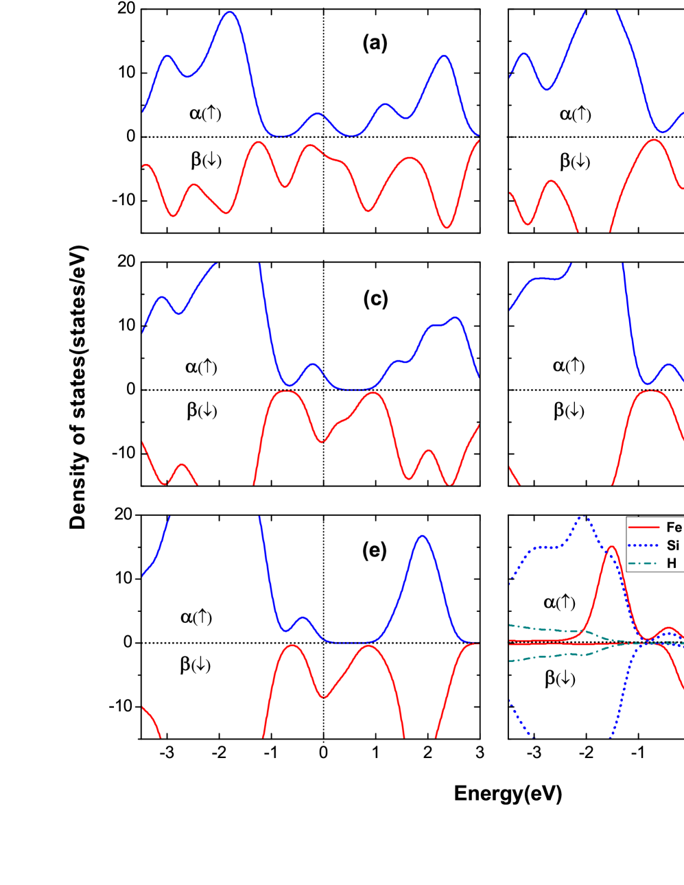
The most intriguing phenomenon occurred when the radii of the Fe-doped hydrogenated silicon tubes increased: a metal to half-metal transition was observed from the spin resolved density of states (DOS) for the and channels of nanotubes, as shown in Fig. 5. From =4 to =6 (Fig. 5(a)–(c)), both the spin and the spin contributed to the DOS at the Fermi level. With the increase in , the DOS peak of the spin at Fermi level shifted down, while the peak of the spin below the Fermi level shifted up towards the Fermi level. When it comes to =7 (Fig. 5 (d))and =8 (Fig. 5 (e)), the spin states disappeared at the Fermi level, and a band gap appeared for this spin channel. For the spin channel, a DOS peak still emerged at the Fermi level. In other words, the nanotube turned into an insulator for spin and a conductor for the spin. From the spin-resolved DOS contributed by Fe, Si and H atoms shown in Fig. 5(f), we found that the centered Fe atoms mainly contributed to the total number of spin states, and Si atoms made only very modest contributions to the states at the Fermi level.
The above phenomenon resulted from the hybridization between Fe and silicon atoms. For small radii of =4, Fe atoms have a stronger hybridization with the outside silicon atoms, but the hybridization becomes smaller as the radius increases. When =7 and 8, the coupling between the Fe atom and the tube becomes so weak that the Fe atom is almost an isolated atom. Thus, the atomic properties of Fe atom were recovered to a large extent. The electron configuration of Fe is 3642. According to Pauli exclusion and Hund’s rule, five 3 electrons would occupy five orbitals with spin, while the last 3 electron will occupy orbitals with spin. When such atoms are weakly coupled together to form a linear chain, highly spin-polarized behavior can result.
Such behavior was also been predicted in Durgun’s workprl256806 which found that hydrogen passivated silicon nanowires could exhibit the half-metallic state when decorated with specific transition metal(TM) atoms. This situation was very similar to the half-metallicity introduced by the weakly coupled carbon atomic chain in single-walled carbon nanotubesapl163105 . In this case, the carbon atoms in the chain have a very weak interactions with their neighbors and the atomic behavior is largely recovered.
The large magnetic moments of the Fe doped silicon nanotubes and their half-metallic behavior are promising for application of these materials in magnetic devices and spintronic applications.
IV CONCLUSIONS
A series of finite and infinite hydrogenated silicon nanotubes were systematically studied by performing first-principles DFT-GGA calculations. Our results demonstrated that one-dimensional SiNTs can be built by stacking clusters along the central axis of the cage. The finite tubes had large HOMO-LUMO gaps. When =5 and 6, the tubes were more stable than other sizes because these tubes had the most suitable bond angles.
Infinite tubes had similar geometric structures to the finite tubes and presented wide gap semiconductivity due to their large band gaps. The band gap decreased monotonously as the radius increased. Endohedral Fe doping greatly modified the properties of the silicon nanotubes. For example, Fe doping can tune the silicon nanotube from semiconductor to metal. Additionally, a metal to half-metal transition was observed in Fe-doped SiNTs with an increasing tube radius. These silicon nanotubes could be useful for nanoelectronic devices. In particular, a half-metallicity of the Fe-doped silicon nanotubes may find important application in spintronics.
V ACKNOWLEDGMENTS
This work was supported by the National Science Foundation of China under Grants No. 10774148 and No. 10904148, the special Funds for Major State Basic Research Project of China(973) under grant No. 2007CB925004, 863 Project, Knowledge Innovation Program of the Chinese Academy of Sciences, and Director Grants of CASHIPS. Some of the calculations were performed at the Center for Computational Science of CASHIPS and at the Shanghai Supercomputer Center.
References
- (1) (a) S. Iijima, Nature(London) 354, 56 (1991). (b) R. E. Smalley and B. I. Yakobson, Sol. Stat. Comm. 107, 597 (1998). (c) H. W. Kroto, J. R. Heath, S. C. O’Brien, R. F. Curl and R. E. Smalley, Nature 318, 162 (1985). (d) K. Hedberg, L. Hedberg, D. S. Bethune, C. A. Brown, H. C. Dorn, R. D. Johnson and M. De Veries, Science 254, 410 (1991).
- (2) F. Rosei, J. Phys.: Condens. Matter 16 S1373 (2004).
- (3) J. G. Han and F. Hagelberg, J. Comput. Theor. Nanosci. 6, 257, (2009) references therein.
- (4) V. Kumar, comp. mater. sci. 36, 1 (2006).
- (5) L. J. Guo, G. F. Zhao, Y. Z. Gu, X. Liu and Z. Zeng, Phys. Rev. B 77, 195417 (2008).
- (6) Q. Peng and J. Shen, J. Chem. Phys. 128, 084711 (2008).
- (7) T. T. Cao, X. J. Feng, L. X. Zhao, X. Liang, Y. M. Lei and Y. H. Luo, Eur. Phys. J. D 49, 343 (2008).
- (8) V. Kumar, A. K. Singh and Y. Kawazoe, Phys. Rev. B 74, , 125411 (2006).
- (9) A. K. Singh, V. Kumar and Y. Kawazoe, Phys. Rev. B 71, 115429 (2006).
- (10) A. D. Zdetsis, Phys. Rev. B 76, 075402 (2007).
- (11) V. Kumar, Y. Kawazoe, Phys. Rev. B 75, 155425 (2007).
- (12) J. Bai, X. C. Zeng, H. Tanaka and J. Y. Zeng, Proc. Natl. Acad. Sci. USA 101, 2664 (2004).
- (13) B. X. li and P. L. Cao, J. Mol. Struct.:THEOCHEM 679, 127 (2004).
- (14) I. Ponomareva, M. Menon, D. Srivastava and A. N. Andriotis, Phys. Rev. Lett. 95, 265502 (2005).
- (15) M. Menon, A. N. Andriotis and G. E. Froudakis, Nano Lett. 2, 301(2002).
- (16) A. K. Singh, V. Kumar, T. M. Briere and Y. Kawazoe, Nano Lett. 2, 1243 (2002).
- (17) J. Bai and X. C. Zeng, NANO: Brief Reports and Reviews 2, 109 (2007).
- (18) A. K. Singh, V. Kumar, T. M. Briere and Y.Kawazoe, J. Mater. Chem. 14, 555 (2004).
- (19) A. N. Andriotis, G. Mpourmpakis, G. E. Froudakis, and M. Menon, New J. Phys. 4, 78 (2002).
- (20) A. K. Singh, T. M. Briere, V. Kumar and Y. Kawazoe, Phys. Rev. Lett. 91, 146802 (2003).
- (21) M. Zhang, Y. H. Han, Q. J. Zang, Z. M. Su and R. S. Wang, Chem. Phys. Lett. 379, 81 (2003).
- (22) E. Durgun, S. Tongay and S. Ciraci, Phys. Rev. B 72, , 075420 (2005).
- (23) X. B. Yang and J. Ni, Phys. Rev. B 72, 195426 (2005).
- (24) A. S. Bamard and S. P. Russo, J. Phys. Chem. B 107, 7577 (2003).
- (25) R. Q. Zhang, H. L. Lee, W. K. Li and B. K. Teo, J. Phys. Chem. B 109, 8605 (2005).
- (26) Solange B. Fagan, R. J. Baierle, R. Mota Silva, Antonio J. R. da Silva and A. Fazzio Phys. Rev. B 61, 9994 (2000).
- (27) J. H. Lan, D. J. Cheng, D. P. Cao and W. C. Wang, J. Phys. Chem. C 112, 5598 (2008).
- (28) B. Marsen and K. Sattler Phys. Rev. B 60,11593 (1999).
- (29) A. Palaria, G. Klimeck and A. Strachan Phys. Rev. B 78, 205315 (2008).
- (30) S. Sirichantaropass, V. M. Garcia-Suarez and C. J. Lambert, Phys. Rev. B 75, 075328 (2008).
- (31) O. Ponomarenko, M. W. Randny and P. V. Smith, Sur. Sci. 562, 257 (2004).
- (32) G. Seifert, Th. Köhler, H. M. Urbassek, E. Hernndez and Th. Frauenheim, Phys. Rev. B 63, 193409 (2001).
- (33) T. He, M. W. Zhao, W. F. Li, C. Song, X. H. Lin, X. D. Liu, Y. Y. Xia and L. M. Mei, J. Phys. Chem. C 111,16840 (2007).
- (34) U. Landman, R. N. Barnett, A. G. Scherbakov and P. Avouris, Phys. Rev. Lett. 85,1958 (2000).
- (35) M. Durandurdu, Phys. Stat. Sol.(b) 243, , No2, R7 (2006).
- (36) B. H. Yan, G. Zhou, J. Wu, W. H. Duan and B. L. Gu, Phys. Rev. B 73, 155432 (2006).
- (37) M. Menon and E. Richter, Phys. Rev. Lett. 83,792 (1999).
- (38) M. W. Zhao, R. Q. Zhang, Y. Y. Xia, C. Song and S. T. Lee, J. Phys. Chem. C 111, 1234 (2007).
- (39) D. D. D. Ma, C. S. Lee, F. C. K. Au, S. Y. Tong and S. T. Lee, Science 299, 1874 (2003).
- (40) J. Sha, J. Niu, X. Ma, J. Xu, X. Zhang, Q. Yang and D. Yang, Adv. Mater. 14, 1219 (2002).
- (41) S. Y. Jeong, J. Y. Kim, H.D. Yang, B.N. Yoon, S. H. Choi, H. K. Kang, C. W. Yang and Y. H. Lee, Adv. Mater. 15, 1172 (2003).
- (42) Y. W. Chen, Y. H. Tang, L. Z. Pei and C. Guo, Adv. Mater. 17, 564 (2005).
- (43) Y. H. Tang, L. Z. Pei, Y. W.Chen and C. Guo, Phys. Rev. Lett. 95, 116102 (2005).
- (44) DMOL is a density-functional theory package distributed by MSI B. Delley, J. Chem. Phys. 92, 508 (1990).
- (45) B. Delley, J. Chem. Phys. 113, 7756 (2000).
- (46) T. Yildirim, O. ;Gülseren and S. Ciraci, Phys. Rev. B 64, 075404(2001).
- (47) M. F. Ng, L. P. Zhou, S. W. Yang, L. Y. Sim, V. B. C. Tan and P. Wu, Phys. Rev. B 76, 155435 (2007).
- (48) E. Durgun, D. Cakir, N. Akman and S. Ciraci, Phys. Rev. Lett. 99, 256806 (2007).
- (49) X. P. Yang and J. M. Dong, Appl. Phys. Lett. 86, 163105 (2005).
VI Figure and Table captions
Table 1. HOMO-LUMO gap() and effective volume per electron of (=4, 5, 6, 7, 8) tubes.
Table 2. Binding energy () of infinite SiH tubes and Fe-doped SiH tubes, the band gap ()of SiH tubes, and the spin moments() per Fe atom and of Fe-doped SiH tubes.
. 1. (Color online) Top view of the optimized clusters (the 1st row) and side view of cluster-assembled nanotubes (all the rest).
. 2. (Color online) Structures of (=3, 4) tubes.
. 3. (Color online) The averaged binding energies, dissociation energies and HOMO-LUMO gaps of finite tubes.
. 4. (Color online) Side views of two unit cells of nanotubes, (a) pristine SiH nanotubes, (b) Fe-doped SiH nanotubes, where the dark atoms in the center of the tube represent Fe atoms.
. 5. (Color online) and spin resolved DOS of Fe-doped SiH nanotubes(). (a)–(e): total and spin DOS of , , , , and , (f): partial and spin DOS of .
| (eV) | (Å3/electron) | |
|---|---|---|
| (=4, =4) | 2.934 | 6.748 |
| (=5, =4) | 2.882 | 6.760 |
| (=6, =4) | 3.006 | 6.653 |
| (=7, =4) | 2.592 | 6.632 |
| (=8, =4) | 2.257 | 6.681 |
| () | |||||
|---|---|---|---|---|---|
| m | (SiH) (eV) | (FeSiH) (eV) | (eV) | per Fe | total |
| 4 | 3.476 | 3.348 | 3.009 | 2.822 | 6.900 |
| 5 | 3.482 | 3.411 | 2.765 | 3.183 | 8.000 |
| 6 | 3.500 | 3.424 | 2.921 | 3.395 | 8.000 |
| 7 | 3.479 | 3.415 | 2.557 | 3.538 | 8.000 |
| 8 | 3.448 | 3.387 | 2.296 | 3.722 | 7.967 |