Multimode quantum interference of photons in multiport integrated devices
Abstract
We report the first demonstration of quantum interference in multimode interference (MMI) devices and a new complete characterization technique that can be applied to any photonic device that removes the need for phase stable measurements. MMI devices provide a compact and robust realization of NM optical circuits, which will dramatically reduce the complexity and increase the functionality of future generations of quantum photonic circuits.
Photonics is a leading approach to realizing future quantum technologies that promise secure communication Gisin and Thew (2007), tremendous computational power Ladd et al. (2010) and the ultimate precision measurements Giovannetti et al. (2004). Optical waveguide circuits on silicon chips have demonstrated high levels of miniaturisation and performance Politi et al. (2008); Matthews et al. (2009); Politi et al. (2009); Laing et al. , however, the construction of large-scale multi-port devices from directional couplers makes them unwieldy and sensitive to wavelength. Multimode interference (MMI) devices promise a straightforward implementation of robust multi-port circuits, however, multi-mode operation could prevent or perturb quantum interference, which to date has not been demonstrated in this architecture. Here we show that quantum interference can be realised in MMI devices, observing a quantum interference visibility of in a MMI coupler. We further demonstrate operation of a port MMI device with photon pairs, which exhibits complex quantum interference behaviour. We have developed a new technique to fully characterise such multi-port devices based on measuring quantum interference for all possible two photon input and output combinations. This approach removes the need for phase sensitive measurements and may find applications for a wide range of photonic devices. These results show that MMI devices can operate in the quantum regime with high fidelity and promise substantial simplification and concatenation of photonic quantum circuits.
Quantum technologies aim to harness superposition and entanglement to enhance communication security, provide exponential computational advantage for particular tasks Deutsch (1985), including factoring Shor (1994), database search Grover (1997) and simulation of important quantum systems Feynman (1982), and reach the ultimate limits of precision in measurement Giovannetti et al. (2004) and lithography Boto et al. (2000). Photons are an appealing information carrier for their inherently low-noise, high-speed transmission and the fact that entangling interactions between photons can be achieved using only linear optical circuits O’Brien et al. (2009); Gisin and Thew (2007); Knill et al. (2001); O’Brien (2007) or mediated by atom-like systems Turchette et al. (1995); Devitt et al. (2007). A photonics approach to these technologies requires complex, multi-port quantum circuits—essentially multi-path, multi-photon interferometers—that exhibit high fidelity quantum interference. Circuits fabricated from directional couplers have demonstrated high performance Politi et al. (2008); Matthews et al. (2009); Politi et al. (2009); Laing et al. ; Marshall et al. (2009), however, construction of more sophisticated multi-port circuits would require their decomposition into a very large number of directional couplers (or X-couplers Smith et al. (2009)). For example, an arbitrary NN mode unitary Reck et al. (1994) would require a sequence of individual directional couplers.
MMI devices are based on the self imaging principle, by which an input field profile is reproduced in single or multiple images at periodic intervals along the propagation direction of a multi-mode waveguide Bryngdahl (1973); Ulrich (1975). The effect is based on the propagation properties of a guide with a large number of lateral modes. MMI devices allow the design of NM splitters with superior performances, excellent tolerance to polarization and wavelength variations and relaxed fabrication requirements compared to the other main beam splitting technology, the directional couplers. Consequently MMI couplers have found applications in a broad range of photonic systems Soldano and Pennings (1995) including phase diversity networks, light switching and modulators, in laser architectures and for optical sensing applications. In the context of photonic quantum circuits they promise to dramatically reduce the complexity of such circuits, including for example those required to generate maximally entangled path or ‘NOON’ states Pryde and White (2003), W states Mikami et al. (2004) and the implementation of NN unitaries Reck et al. (1994).
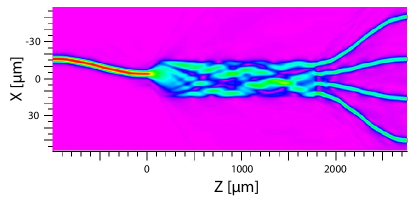
In contrast to directional couplers, the self-imaging effect in MMIs allows the flexibility to directly realize symmetric NN multi-port devices with several input and output ports. Multi-port circuits are particularly promising for quantum optics and information purposes and fundamental experiments have been conducted to study the behaviour of non-classical interference of single photons in bulk optics Mattle et al. (1995) and fibre Weihs et al. (1996) circuits. However, their performance is limited by stability and control of the splitting ratios. The implementation of multi-port splitters in MMI devices should allow higher performances due to the monolithic and scalable architecture, with the caveat that quantum interference has not been observed in such devices: multimode properties (see Fig. 1(b)) might at first seem undesirable in a quantum circuit since they typically perturb or destroy quantum interference.
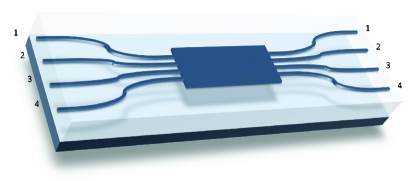
MMI devices, including and couplers, were designed and simulated using a commercial beam propagation package (Fig. 1(b)). They were fabricated on a 4” silicon wafer, onto which a 16 m lower cladding layer of thermally grown undoped silica was deposited, followed by a 3.5 m core layer of silica doped with germanium and boron oxides deposited by flame hydrolysis. This core layer was patterned into 3.5 m wide single- and 15 and 29 m wide multi-mode waveguides via standard optical lithographic techniques and then overgrown with a 16 m upper cladding of phosphorus and boron doped silica with a refractive index matched to that of the lower cladding; simulations indicated single mode operation at 780 nm. The devices are composed of N single mode waveguides that serve as input and output for the multi-mode section and terminate with a separation of 250 m at the edges of the device to allow input and output coupling with a polarization maintaining fibre array. The MMIs are composed of two input and two output waveguides that have a separation of 11 m at the interface of the single- and multi-mode region. The multimode region measures m. In the case of the MMIs, the waveguides are separated by 8 m at the interface to the multi-mode section, which measures m.
Ideally, a balanced MMI splitter should perform the same operation as a directional coupler with a unitary matrix that describes the evolution from input to output Matthews et al. (2009):
| (1) |
which equally superposes the two modes (equivalent to the Hadamard operation with a phase shift 111In the case, there is only one equivalence class of symmetric splitters, this corresponds to the fact that different physical implementations can have different external phase relations, but the general description of the transformation is dictated by the unitary evolution Zukowski et al. (1997).). However, it is not clear that the multi-mode nature of MMI devices will allow quantum operations, in particular quantum interference.
Quantum interference with two photons is a defining distinction between classical and quantum states of light and is the key phenomenon that drives photonic quantum technologies. Quantum interference occurs when different quantum mechanical outcomes are indistinguishable. In the case of two photons entering the two input ports of a symmetric unitary beamsplitter (one photon per input port) the outcomes of “both photons reflected” and “both photons transmitted” are indistinguishable. In this case the interference is destructive so that the photons never leave in the two separate outputs, but a superposition of two photons in each output. This behaviour is in stark contrast to the case of two classical particles which would have a probability of 1/2 to leave in separate outputs. When the relative arrival time of the two photons is scanned, a characteristic “HOM” dip is observed Hong et al. (1987) because the classical probability of 1/2 holds for finite delay and the quantum probability of zero holds for zero delay. The width of this HOM dip is related to the coherence time of the photons. The visibility of the dip (how close it gets to zero) is a measure of the degree of quantum interference. Any information that distinguishes the two probability amplitudes—eg. the photons have different polarizations, frequency, bandwidth etc.—reduces . A key advantage of directional coupler devices is that single mode waveguides mean that no spatial mode distinguishability is possible. In contrast, MMI devices are by definition highly multi-mode in the interaction region.
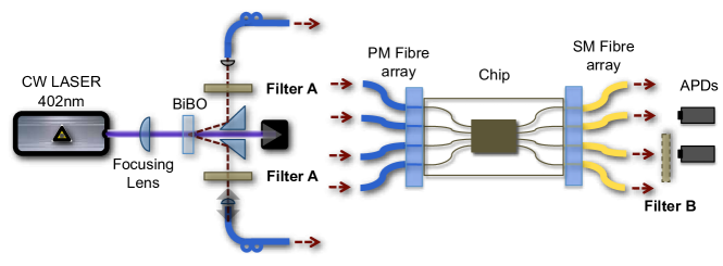
We measured quantum interference in MMI devices using single photon pairs produced in the spontaneous parametric down-conversion (SPDC) source shown schematically in Fig. 2: a type-I BiBO crystal pumped with a 60 mW CW laser diode at 402 nm, producing 804 nm pairs of photons. These photons were collected into single mode polarization maintaining (PM) fibres after passing through 2 nm filters. The source was constructed in such a way that quantum interference with was routinely observed, confirmed with a directional coupler that has previously exhibited (Ref. Laing et al., ) 222All the visibilities quoted in this paper except those for the 4x4 MMI are corrected for accidentals Laing et al. .
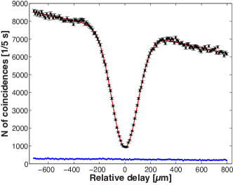
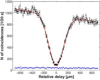
We observed the HOM dip shown in Fig. 3 in a MMI coupler. These data provide conclusive evidence that quantum interference does indeed occur in a MMI device (the linear slope in these data is due to decoupling of the input fibre as the timing delay is changed). However, the measured is significantly lower than the obtainable from the SPDC source. The reason is that the propagation in the multi-mode section of the MMI introduces some distinguishability between the photons. We experimentally ruled out spatial, spectral and polarization mismatch of the photons, implicating the temporal degree of freedom. The different modes in the multimode section of the device see different effective refractive indices, which introduces a jitter in the time of flight of the photons from the input to the output waveguides, providing “which path” distinguishing information, and thereby reducing .
To confirm that this temporal jitter effect is the origin of the reduced visibility, we inserted a narrower 0.5 nm filter in one of the output modes between the device and the detector (as indicated in Fig. 2), i.e. not affecting the properties of the photon source, but simply increasing the coherence length of the photons. The additional filter acts as a quantum eraser Kwiat et al. (1992), that erases the timing information by increasing the coherence time of the photons. Under these experimental conditions, we observed the HOM dip plotted in Fig. 3 in the same MMI device. In this case , confirming that timing jitter limits the visibility for the data shown in Fig. 3 (the larger error bar is due to the lower count rate with the narrower filter). These data confirm that quantum interference occurs in MMI devices, and that the coherence length of the photons must be sufficiently long compared to the timing jitter that is introduced as a result of the different refractive indices of the MMI modes.
Interestingly, the description of multi-port splitters grows in complexity with N. For N all symmetric N N splitters can be described by one equivalence class, since the requirement on the conservation of energy defines the matrix to within external phases on the input and outputs. However, when N there exists an infinite number of distinct equivalence classes Bernstein (1974) and internal free phases are independent of the conservation of energy Pryde and White (2003). The transition matrix that describes an ideal symmetric MMI splitter is:
| (2) |
where is the free internal phase. In general, two different physical implementations would correspond to a different equivalence class, and a different value of .
In the case of a MMI splitter the value of the internal phase is, in principle, dictated by the self-imaging condition Soldano and Pennings (1995). However, the presence of fabrication imperfections in the device would drive the multi-mode section away from exact self-imaging, and the relation between the optical phases would deviate from the expected value. Moreover, the presence of unavoidable losses in the MMI coupler corresponds to the presence of additional optical modes in the transition matrix of the splitter, thus making the reduced transition matrix more complicated than Eq. 2. In principle, could be reconstructed using a number of phase sensitive measurements. Such measurements are, however, difficult in practice, due to the need to maintain sub-wavelength stability in interferometers consisting of waveguide and fibre and/or free space paths. We have developed a technique to overcome this using only intensity measurements and two photon quantum measurements, but no phase sensitive measurements, as described below.
In contrast to the MMI device in which quantum interference is destructive, the MMI device interference between indistinguishable outcomes can be constructive for some of the 36 possible input and output combinations Mattle et al. (1995). We characterised the quantum operation of a MMI splitter by inputing the state —i.e a single photon in each input waveguide and . We considered all six combinations of two photons in four inputs, where (we did not consider the case of both photons in the same input since this does not give rise to quantum interference—i.e. such measurements provide no more information than bright intensity measurements do). As in the case of the HOM dip, quantum interference is revealed in the correlations in the output probability distribution. The probability to detect one photon in each output and , when two indistinguishable photons are injected into inputs and is given by:
| (3) |
where is Kronecker’s delta and is the element of the transition matrix. In the case of two distinguishable photons (equivalent to the classical analogue) the probability is given by
| (4) |
and there is no interference between the two terms. Measurement of the generalized non-classical interference between two photons enables the reconstruction of the matrix via measurement of the detection probabilities and , as described below.
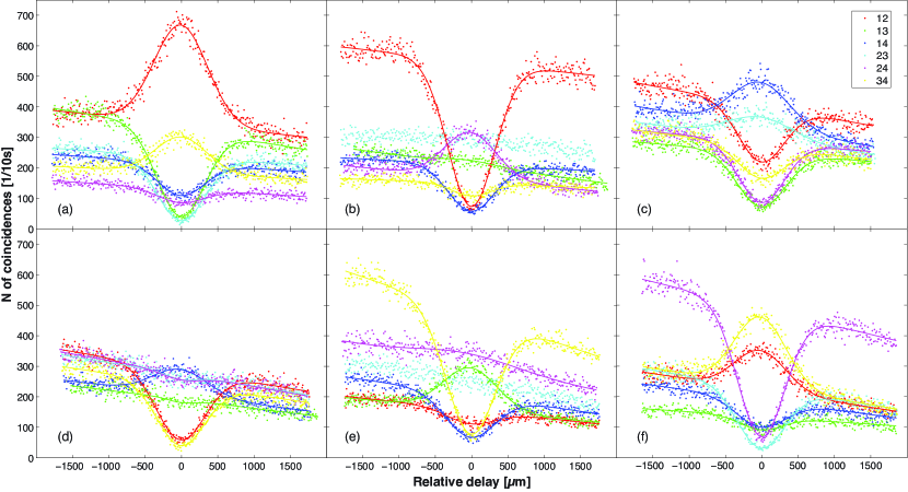
Figure 4 shows the rate of detecting two photons at the six possible output pairs of waveguides, for each of the six different input states of a MMI splitter, as a function of the relative arrival time of the photons. For some input-output combinations, these data exhibit clear interference dips, analogous to the HOM dip. However, for other combinations there are peaks, and essentially straight curves. These behaviours are the result of the phase values of the matrix and are conveniently summarised by plotting the visibility of the non-classical peak or dip, given by:
| (5) |
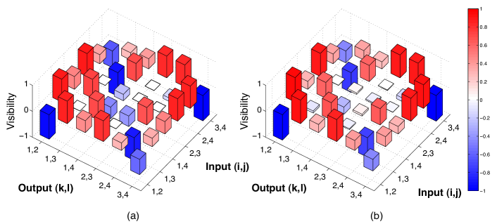
where positive values indicate a dip and negative values a peak. Fig. 5(a) shows the 66 matrix of measured visibilities obtained from the data of Fig. 4.
We have developed a technique that uses only the values and the classical intensity ratios to reconstruct the (reduced) transition matrix that describes the MMI device, assuming linearity of the device. To do this, we numerically search for a matrix that minimizes the RMS distance between the experimentally measured and the reconstructed that corresponds to . The classical intensity ratios were measured using a CCD camera at the output of the integrated chip. The numerical optimization produces333Note that since the elements of each row are normalized to 1 and the device includes some loss, which is considered explicitly via the addition of more modes, the sum of each column can be greater 1.
The quality of the reconstructed transition matrix is confirmed by comparing the measured and calculated matrices in Fig. 5. Additional optimization routines were performed with different initialization parameters, to confirm that the measured transmissivities do indeed provide a good starting condition for the matrix . It is interesting to note that this method to reconstruct the transition matrix can be used for any unknown linear optical element (where no decoherence or measurement is present), even in the case of losses. It is possible to calculate the reduced transition matrix even in the case of large NN (N) networks in which only input and output modes are accessible for measurements.
Interestingly, the computation of the photon distribution at the output of a multi-port circuit with many photons is a hard problem to solve from a computational perspective. The coincidence probability distribution is related to the permanent of the matrix that describes the multiport device Scheel (2004). Since the computation of the permanent of a matrix is a computationally difficult problem, the measurement of the coincidence probability in a device with many photons and many ports could represents a feasible implementation of quantum simulation that uses the bosonic nature of the photons to realize a hard computation. In general, it is possible to map the calculation of the permanent to the detection of multiphoton coincidences in the appropriate splitter. Although the form of the transition matrix that characterizes the MMI device is in principle fixed by the self-imaging condition, and no reconfigurability is possible, the data presented here on a MMI splitter is the first small-scale example of such a quantum computation Aaronson (2010).
Multi-photon inputs to multi-port devices are not only an essential ingredient of future photonic quantum technologies, but enable the study of a rich variety of quantum interference phenomena to be studied Campos (2000). The increasing need for more complex photonic networks will present the problem of the characterization of such integrated circuits and their imperfections. As demonstrated here, it is possible to take advantage of the properties of quantum states of light to reconstruct the behaviour of a photonic network, without the need of complex phase stable measurements. In the case of quantum networks, MMI devices promise to dramatically simplify and miniaturize the implementation of quantum circuits, thanks to the possibility of performing complex multi-mode evolution of many photons in a single compact device.
We thank J. C. F. Matthews and J. G. Rarity for helpful discussions. This work was supported by EPSRC, ERC, the Leverhulme Trust, QIP IRC, IARPA and NSQI. J.L.O’B. acknowledges a Royal Society Wolfson Merit Award.
References
- Gisin and Thew (2007) N. Gisin and R. Thew, Nature Photon. 1, 165 (2007).
- Ladd et al. (2010) T. D. Ladd, F. Jelezko, R. Laflamme, Y. Nakamura, C. Monroe, and J. L. O’Brien, Nature 464, 45 (2010).
- Giovannetti et al. (2004) V. Giovannetti, S. Lloyd, and L. Maccone, Science 306, 1330 (2004).
- Politi et al. (2008) A. Politi, M. J. Cryan, J. G. Rarity, S. Yu, and J. L. O’Brien, Science 320, 646 (2008).
- Matthews et al. (2009) J. C. F. Matthews, A. Politi, A. Stefanov, and J. L. O’Brien, Nature Photonics 3, 346 (2009).
- Politi et al. (2009) A. Politi, J. C. F. Matthews, and J. L. O’Brien, Science 325, 1221 (2009).
- (7) A. Laing, A. Peruzzo, A. Politi, M. R. Verde, M. Halder, T. C. Ralph, M. G. Thompson, and J. L. O’Brien.
- Deutsch (1985) D. Deutsch, Proc. R. Soc. Lond. A 400, 97 (1985).
- Shor (1994) P. W. Shor, Proc. 35th Annu. Symp. Foundations of Computer Science and IEEE Computer Society and Los Alamitos and CA pp. 124–134 (1994), ed. S. Goldwasser.
- Grover (1997) L. K. Grover, Phys. Rev. Lett. 79, 325 (1997).
- Feynman (1982) R. Feynman, Int. J. Thy. Phys. 21, 467 (1982).
- Boto et al. (2000) A. N. Boto, P. Kok, D. S. Abrams, S. L. Braunstein, C. P. Williams, and J. P. Dowling, Phys. Rev. Lett. 85, 2733 (2000).
- O’Brien et al. (2009) J. L. O’Brien, A. Furusawa, and J. Vuckovic, Nature Photonics 3, 687 (2009).
- Knill et al. (2001) E. Knill, R. Laflamme, and G. J. Milburn, Nature 409, 46 (2001).
- O’Brien (2007) J. L. O’Brien, Science 318, 1567 (2007).
- Turchette et al. (1995) Q. A. Turchette, C. J. Hood, W. Lange, H. Mabuchi, and H. J. Kimble, Phys. Rev. Lett. 75, 4710 (1995).
- Devitt et al. (2007) S. J. Devitt, A. D. Greentree, R. Ionicioiu, J. L. O’Brien, W. J. Munro, and L. C. L. Hollenberg, Physical Review A (Atomic, Molecular, and Optical Physics) 76, 052312 (pages 7) (2007).
- Marshall et al. (2009) G. D. Marshall, A. Politi, J. C. F. Matthews, P. Dekker, M. Ams, M. J. Withford, and J. L. O’Brien, Opt. Express 17, 12546 (2009).
- Smith et al. (2009) B. J. Smith, D. Kundys, N. Thomas-Peter, P. G. R. Smith, and I. A. Walmsley, Opt. Express 17, 13516 (2009).
- Reck et al. (1994) M. Reck, A. Zeilinger, H. J. Bernstein, and P. Bertani, Phys. Rev. Lett. 73, 58 (1994).
- Bryngdahl (1973) O. Bryngdahl, J. Opt. Soc. Am. 63, 416 (1973).
- Ulrich (1975) R. Ulrich, Nouvelle Revue d’Optique 6, 253 (1975).
- Soldano and Pennings (1995) L. Soldano and E. Pennings, Lightwave Technology, Journal of 13, 615 (1995).
- Pryde and White (2003) G. J. Pryde and A. G. White, Phys. Rev. A 68, 052315 (2003).
- Mikami et al. (2004) H. Mikami, Y. Li, and T. Kobayashi, Phys. Rev. A 70, 052308 (2004).
- Mattle et al. (1995) K. Mattle, M. Michler, H. Weinfurter, A. Zeilinger, and M. Zukowski, Applied Physics B: Lasers and Optics 60, S111 (1995).
- Weihs et al. (1996) G. Weihs, M. Reck, H. Weinfurter, and A. Zeilinger, Phys. Rev. A 54, 893 (1996).
- Hong et al. (1987) C. K. Hong, Z. Y. Ou, and L. Mandel, Phys. Rev. Lett. 59, 2044 (1987).
- Kwiat et al. (1992) P. G. Kwiat, A. M. Steinberg, and R. Y. Chiao, Phys. Rev. A 45, 7729 (1992).
- Bernstein (1974) H. J. Bernstein, Journal of Mathematical Physics 15, 1677 (1974).
- Scheel (2004) S. Scheel, Permanents in linear optical networks (2004).
- Aaronson (2010) S. Aaronson, private communication (2010).
- Campos (2000) R. A. Campos, Phys. Rev. A 62, 013809 (2000).
- Zukowski et al. (1997) M. Zukowski, A. Zeilinger, and M. A. Horne, Phys. Rev. A 55, 2564 (1997).