Correlated flux noise and decoherence in two inductively coupled flux qubits
Abstract
We have studied decoherence in a system where two Josephson-junction flux qubits share a part of their superconducting loops and are inductively coupled. By tuning the flux bias condition, we control the sensitivities of the energy levels to flux noises in each qubit. The dephasing rate of the first excited state is enhanced or suppressed depending on the amplitudes and the signs of the sensitivities. We have quantified the flux noises and their correlations and found that the dominant contribution is by local fluctuations.
pacs:
03.67.Lx,85.25.Cp,74.50.+rThe presence of low-frequency flux noise in superconducting devices has been known for decades. It was discovered as an excess noise in SQUIDs Koch et al. (1983); Wellstood et al. (1987) and has recently been intensively studied as a source of dephasing in various types of superconducting qubits, such as charge, Ithier et al. (2005) flux, Yoshihara et al. (2006); Kakuyanagi et al. (2007); Lanting et al. (2009); Harris et al. (2008, ) and phase qubits. Claudon et al. (2006); Bialczak et al. (2007); Bennett et al. (2009) The noise spectrum typically follows 1/ frequency dependence with a spectral density of about 1-40 at 1 Hz, where is the superconducting flux quantum. The noise spectrum depends only weakly on geometry—samples with a loop area of 1 up to a few mm2 are within the above range—and does not show a clear dependence on the material used. However, the microscopic origin of the noise has been elusive so far. It is crucial to identify and eliminate the source of such noise in order to improve the performance of these devices; i.e., the sensitivity of SQUIDs and coherence of qubits.
A few recent experimental observations have suggested as the source of the flux noise a high density of electron spins existing on the surface of superconducting electrodes. Rogachev et al. attributed the magnetic-field-induced enhancement of the critical current in superconducting nanowires to suppression of spin-flip scattering at the surface, Rogachev et al. (2006) while Sendelbach et al. directly measured the magnetization of SQUIDs at low temperatures as well as correlated inductance fluctuations. Sendelbach et al. (2008, 2009) Electron spin resonance studies on Si/SiO2 interfaces Schenkel et al. (2006) as well as scanning-SQUID measurements on Au surfaces Bluhm et al. (2009) have also indicated the presence of electron spins. As the microscopic origins of these surface spins, theoretical studies have proposed localized electrons at disordered interfaces between surface oxides and metals/semiconductors de Sousa (2007); Faoro and Ioffe (2008); Choi et al. (2009) or at defects in the surface oxides. Koch et al. (2007)
In the present study, we approached this issue by means of dephasing measurements in coupled flux qubits. Decoherence in coupled qubits depends on the correlations between noises in each qubit. Governale et al. (2001); Storcz and Wilhelm (2003); You et al. (2005); Hu et al. (2007); D’Arrigo et al. (2008) It can therefore be used to characterize the noise correlations without the need for measuring the correlations directly. In the echo decay signal of the qubits, we observed the contributions of pure dephasing due to flux noises and evaluated the correlations. The results indicated local rather than global flux fluctuations in accordance with the surface spin model.
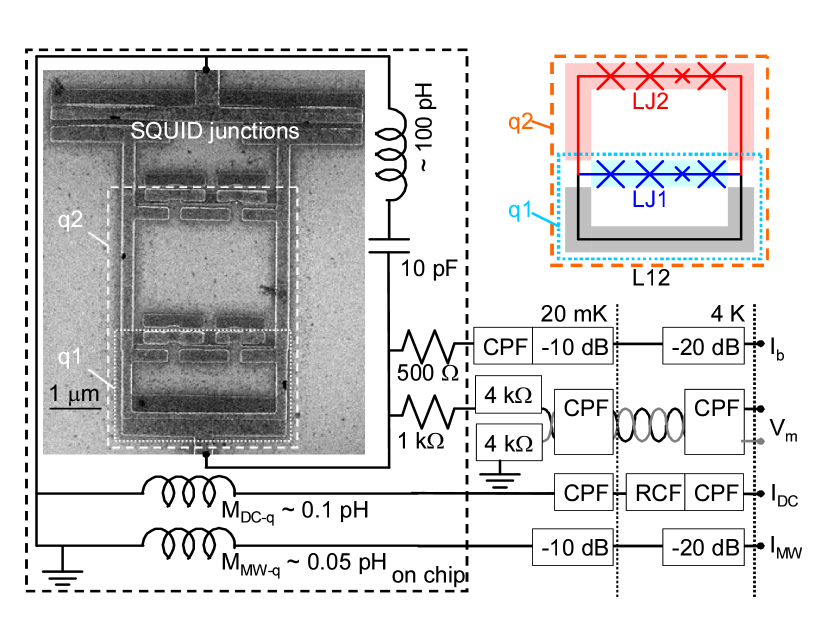
The experiments were carried out using a sample fabricated by electron-beam lithography and shadow evaporation of Al films, with a 20 nm-thick first layer and 30 nm-thick second layer, on a non-doped Si wafer with a 300 nm-thick SiO2 layer (Fig. 1). The qubits formed a small superconducting loop intersected by four Josephson junctions, among which one was smaller than the others by a nominal factor of 0.55. The sample consisted of two flux qubits, q1 and q2, coupled with each other via kinetic inductance of the shared part. The area ratio of q1 and q2 was designed to be 1:3 so that the two qubits could be closely biased to their half-integer flux-bias points simultaneously by a global magnetic field. The conditions were and , where is the externally applied flux through qubit . An additional on-chip local flux bias line made of Al allowed independent control of the flux biases in each qubit.
The effective Hamiltonian of a system with two inductively coupled flux qubits can be expressed in terms of persistent current basis as
| (1) |
where and are Pauli matrices, is the tunnel splitting between the two states with opposite directions of persistent current along the loop, is the energy bias between the two states, and is the persistent current along the qubit loop. The qubits are coupled with a coupling energy , where is the mutual inductance. We define the normalized magnetic flux in each qubit loop as . In the case of an isolated qubit, and at , where is the eigenenergy of the first excited state. This is the optimal flux bias condition where dephasing due to fluctuations of is minimal.
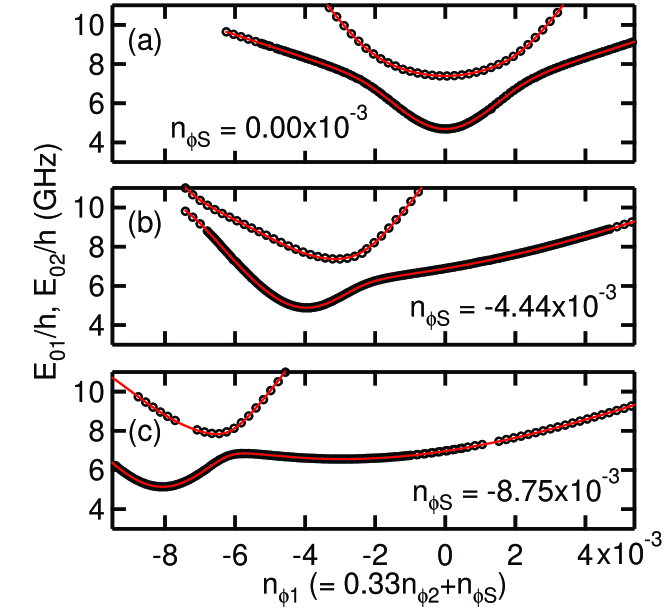
In our experimental setup, the energies of the first and second excited states, and , in the two-qubit system are measured by spectroscopy. A 5 microwave pulse is applied to the system, followed by a bias current pulse of the readout SQUID. When the microwave frequency hits a transition of the system, the excitation is detected as a change in the SQUID switching probability . Chiorescu et al. (2003) Figure 2 shows the results as a function of the global flux bias. By sweeping the global flux bias, and vary according to the equation , where is an offset between the optimal flux bias points of the two qubits. For , the optimal bias points of q1 and q2 are aligned, while the optimal point of q2 shifts toward the left with decreasing . The energy levels show anticrossings due to the strong inductive coupling between the qubits.
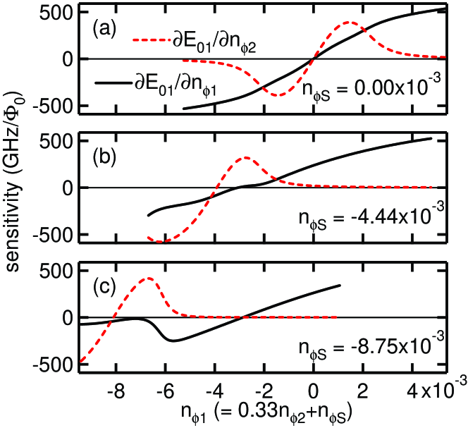
The data fit well with the calculated eigenenergies, indicating that the system can be simply described with two qubits and a fixed coupling between them. The fitting parameters obtained from the least-squares method are as follows: GHz, GHz, nA, nA, and GHz. By partially differentiating with respect to and , we also obtain energy sensitivities of the first excited state in the two-qubit system to flux noises in q1 and q2; i.e., and (Fig. 3), respectively.
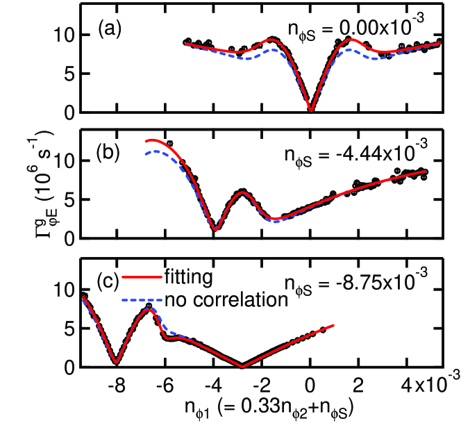
Dephasing of the first excited state is characterized by Hahn echo measurement with a sequence of -- pulses. Hahn (1950) The echo decay curve contains both relaxation component and pure dephasing component such that . The first term is determined independently by energy relaxation measurement, while the latter is fitted well by a Gaussian decay, .Yoshihara et al. (2006) Figure 4 shows obtained for three different . The sample has relatively good coherence: the smallest dephasing rate s-1 is observed for and at , where s-1. The decay of the echo signal by a factor of takes place in .
We have also examined the SQUID-bias-current dependence of and confirmed that the noise from the bias current line does not significantly contribute to the pure dephasing. Yoshihara et al. (2006) Because of the strong dependence of , we can also rule out possible contributions of charge and critical-current noise to the dephasing.
The observed Gaussian decay implies the presence of low-frequency energy fluctuations with a 1/ spectrum,
| (2) | |||||
It also requires that the high-frequency tail extends up to the angular frequency range comparable to , which is MHz in the present sample. The echo dephasing rate is then expressed as . Cottet
As the origin of the energy fluctuations, it is most natural to assume the presence of 1/ flux noises in each qubit: (=1,2). Yoshihara et al. (2006) Here we also consider cross correlations between the two flux fluctuations, and . Following the linear cross approximation discussed in Ref. 24,
| (3) | |||||
This form of cross-correlation spectrum is justified when the noise is produced by many two-level systems and their coupling strengths to the qubits and switch rates are uncorrelated. For charge noise, such cross correlations in charge noise have been observed using two single-electron transistors.Zorin et al. (1996) Now we fit the observed Gaussian decay rate using
| (4) | |||||
(red solid curves in Fig. 4). All the data points of for different flux biases are fitted with a single set of parameters, , , and , which confirms the validity of our assumption of dephasing induced by flux noises. Moreover, the noise amplitudes, similar to the previously reported values, are determined with high accuracy. We also note that the data cannot be fitted well if is set to zero.
The small ratios and are clear proofs that global flux noise is not a dominant source for the dephasing in the first excited state: global flux noise would give rise to and due to the difference between the areas of q1 and q2.
On the other hand, we obtain a non-negligible amount of , which indicates noticeable correlations between and . In Fig. 4, dephasing rates calculated without taking into account the correlation term are plotted as blue dotted curves. The observed dephasing rate is enhanced (suppressed) when sensitivities and have the same (opposite) signs. For example, at around for , reduction of the dephasing rate due to the correlation is observed.
To qualitatively account for the flux noise amplitudes , , and especially the correlation term , we introduce a simple model where flux noises are generated by a number of microscopic sources, described as fluctuating magnetic dipoles, scattered over the sample. The two-qubit system can be divided into three segments (see the inset of Fig. 1): a part of the q1 loop and its junctions (LJ1), a part of the q2 loop and its junctions (LJ2), and the common part of the two loops (L12). Coupling between each dipole and a qubit reaches a maximum when the dipole sits on the surface of the superconducting loops, while dipoles away from the surface do not couple effectively. Koch et al. (2007) For such sources on the surface, we further apply the following approximation: Sources along LJ1 (LJ2) couple exclusively to q1 (q2) and those along L12 couple equally to both q1 and q2. For the latter, and have full correlations.
Summing up all the contributions of dephasing from LJ1, LJ2, and L12, can be rewritten as
| (5) | |||||
The noise amplitudes in each part of the system are calculated as , , and , which represent the distribution of flux noise sources on the loops. Two points are worth mentioning here: (i) There are two parts of the system, (L12 + LJ1) and LJ2, each consisting of four Josephson junctions and a similar length of superconducting loops. The noise amplitudes in the (L12 + LJ1) part are calculated as , which coincides with . This result is consistent with the model and the assumption of the local flux noises. (ii) The third term in Eq.(5) originating from L12 can be cancelled when the sensitivities satisfy the equation, .
In conclusion, we have studied dephasing in two inductively coupled flux qubits. The dominant source of the dephasing is found to be low-frequency flux noises. At the same time, the local, rather than global, nature of the flux noises is revealed in the correlations between the noises in each qubit. The results agree with a model in which flux noise sources are distributed on the surface of superconducting loops.
We are grateful to L. Ioffe, M. Rötteler, J. Pekola, W. Oliver, E. Paladino, and P. Billangeon for their valuable discussions, and to K. Harrabi for assistance with the experiments. This work was supported by the CREST program of the Japan Science and Technology Agency (JST) and the Grant-in-Aid for Scientific Research Program for Quantum Cybernetics of the Ministry of Education, Culture, Sports, Science and Technology (MEXT), Japan.
References
- Koch et al. (1983) R. H. Koch, J. Clarke, J. M. Martinis, W. M. Goubau, C. M. Pegrum, and D. J. Van Harlingen, IEEE T. Magn. 19, 449 (1983).
- Wellstood et al. (1987) F. C. Wellstood, C. Urbina, and J. Clarke, Appl. Phys. Lett. 50, 772 (1987).
- Ithier et al. (2005) G. Ithier, E. Collin, P. Joyez, P. J. Meeson, D. Vion, D. Esteve, F. Chiarello, A. Shnirman, Y. Makhlin, J. Schriefl, et al., Phys. Rev. B 72, 134519 (2005).
- Yoshihara et al. (2006) F. Yoshihara, K. Harrabi, A. O. Niskanen, Y. Nakamura, and J. S. Tsai, Phys. Rev. Lett. 97, 167001 (2006).
- Kakuyanagi et al. (2007) K. Kakuyanagi, T. Meno, S. Saito, H. Nakano, K. Semba, H. Takayanagi, F. Deppe, and A. Shnirman, Phys. Rev. Lett. 98, 047004 (2007).
- Lanting et al. (2009) T. Lanting, A. J. Berkley, B. Bumble, P. Bunyk, A. Fung, J. Johanson, A. Kaul, A. Kleinsasser, E. Ladizinsky, F. Maibaum, et al., Phys. Rev. B 79, 060509(R) (2009).
- Harris et al. (2008) R. Harris, M. W. Johnson, S. Han, A. J. Berkley, J. Johansson, P. Bunyk, E. Ladizinsky, S. Govorkov, M. C. Thom, S. Uchaikin, et al., Phys. Rev. Lett. 101, 117003 (2008).
- (8) R. Harris, J. Johansson, A. J. Berkley, M. W. Johnson, T. Lanting, S. Han, P. Bunyk, E. Ladizinsky, T. Oh, I. Perminov, et al., eprint arXiv:0909.4321.
- Claudon et al. (2006) J. Claudon, A. Fay, L. P. Lévy, and O. Buisson, Phys. Rev. B 73, 180502(R) (2006).
- Bialczak et al. (2007) R. C. Bialczak, R. McDermott, M. Ansmann, M. Hofheinz, N. Katz, E. Lucero, M. Neeley, A. D. O’Connell, H. Wang, A. N. Cleland, et al., Phys. Rev. Lett. 99, 187006 (2007).
- Bennett et al. (2009) D. A. Bennett, L. Longobardi, V. Patel, W. Chen, D. V. Averin, and J. E. Lukens, Quant. Inf. Proc. 8, 217 (2009).
- Rogachev et al. (2006) A. Rogachev, T. C. Wei, D. Pekker, A. T. Bollinger, P. M. Goldbart, and A. Bezryadin, Phys. Rev. Lett. 97, 137001 (2006).
- Sendelbach et al. (2008) S. Sendelbach, D. Hover, A. Kittel, M. Mück, J. M. Martinis, and R. McDermott, Phys. Rev. Lett. 100, 227006 (2008).
- Sendelbach et al. (2009) S. Sendelbach, D. Hover, M. Mück, and R. McDermott, Phys. Rev. Lett. 103, 117001 (2009).
- Schenkel et al. (2006) T. Schenkel, J. A. Liddle, A. Persaud, A. M. Tyryshkin, S. A. Lyon, R. de Sousa, K. B. Whaley, J. Bokor, J. Shangkuan, and I. Chakarov, Appl. Phys. Lett. 88, 112101 (2006).
- Bluhm et al. (2009) H. Bluhm, J. A. Bert, N. C. Koshnick, M. E. Huber, and K. A. Moler, Phys. Rev. Lett. 103, 026805 (2009).
- de Sousa (2007) R. de Sousa, Phys. Rev. B 76, 245306 (2007).
- Faoro and Ioffe (2008) L. Faoro and L. B. Ioffe, Phys. Rev. Lett. 100, 227005 (2008).
- Choi et al. (2009) S. K. Choi, D. H. Lee, S. G. Louie, and J. Clarke, Phys. Rev. Lett. 103, 197001 (2009).
- Koch et al. (2007) R. H. Koch, D. P. DiVincenzo, and J. Clarke, Phys. Rev. Lett. 98, 267003 (2007).
- Governale et al. (2001) M. Governale, M. Grifoni, and G. Schön, Chem. Phys. 268, 273 (2001).
- Storcz and Wilhelm (2003) M. J. Storcz and F. K. Wilhelm, Phys. Rev. A 67, 042319 (2003).
- You et al. (2005) J. Q. You, X. Hu, and F. Nori, Phys. Rev. B 72, 144529 (2005).
- Hu et al. (2007) Y. Hu, Z.-W. Zhou, J.-M. Cai, and G.-C. Guo, Phys. Rev. A 75, 052327 (2007).
- D’Arrigo et al. (2008) A. D’Arrigo, A. Mastellone, E. Paladino, and G. Falci, New J. Phys. 10, 115006 (2008).
- Chiorescu et al. (2003) I. Chiorescu, Y. Nakamura, C. J. P. M. Harmans, and J. E. Mooij, Science 299, 1869 (2003).
- Hahn (1950) E. L. Hahn, Phys. Rev. 80, 580 (1950).
- (28) A. Cottet, eprint Ph.D. thesis, Université Paris VI (2002).
- Zorin et al. (1996) A. B. Zorin, F.-J. Ahlers, J. Niemeyer, T. Weimann, H. Wolf, V. A. Krupenin, and S. V. Lotkhov, Phys. Rev. B 53, 13682 (1996).