On the complex dynamics of a red blood cell in simple shear flow
Abstract
Motivated by the reported peculiar dynamics of a red blood cell in shear flow, we develop an analytical theory for the motion of a nearly–spherical fluid particle enclosed by a visco–elastic incompressible interface in linear flows. The analysis explains the effect of particle deformability on the transition from tumbling to swinging as the shear rate increases. Near the transition, intermittent behavior is predicted only if the particle has a fixed shape; the intermittency disappears for a deformable particle. Comparison with available phenomenological models based on the fixed shape assumption highlights their physical foundations and limitations.
1 Introduction
A membrane–enclosed particle, such as the red blood cell (RBC), exhibits rich dynamics in flow (see for recent reviews Abkarian & Viallat (2008); Vlahovska et al. (2009b); Guido & Tomaiuolo (2009)). Two classic types of behavior in steady shear flow are (1) tank–treading (TT), in which the RBC shape is steady and the membrane rotates as a tank-tread; the cell major axis is tilted with respect to the flow direction and the inclination angle remains fixed in time, and (2) tumbling (TB), in which the RBC undergoes a periodic flipping motion. Recently, a new type of motion called swinging (SW) has been experimentally observed Abkarian et al. (2007). In this case, the RBC’s tank–treading is accompanied by small oscillations in the inclination angle. Similar phenomenon has been reported for capsules Walter et al. (2001); Ramanjuan & Pozrikidis (1998); Navot (1998) and drops covered with adsorbed protein layer Erni et al. (2005).
The variety of RBC’s motions stems from the unique mechanical properties of the interface. The cell membrane is made of a lipid bilayer attached to an underlying spectrin network. The lipid bilayer behaves as a two–dimensional incompressible fluid, while the polymer network endows the membrane with shear elasticity. Closed lipid membranes (vesicles) display TT, TB but no SW Kantsler & Steinberg (2005); Mader et al. (2006); Kantsler & Steinberg (2006); Deschamps et al. (2009a, b). The inclination angle can oscillate around the flow direction Kantsler & Steinberg (2006); Mader et al. (2006); Barthes-Biesel & Sgaier (1985), but this breathing (VB, also called trembling) motion differs from the swinging observed with RBCs; in the latter case, swinging does not necessarily involve shape deformation.
The type of motion a vesicle or RBC undergoes depends on the viscosity mismatch between the inner and suspending fluids, applied shear rate, and the non-sphericity of the rest shape. For a given viscosity ratio and shape, at low shear rates the RBC tumbles because elastic tensions immobilize the interface causing the cell to behave as a solid object. At high shear rates the applied stress overcomes the elastic tensions and drags the membrane in motion. As a result, the RBC adopts a steady TT shape whose major axis “swings”. This motion originates from the unstressed non-spherical shape of the RBC, in which membrane elements at the equator and the poles are not equivalent. During one TT–period, an element passes twice through its unstressed position where it releases elastic energy. As the shear rate increases, the amplitude of the angle oscillations decreases.
Phenomenological studies of swinging Abkarian et al. (2007); Skotheim & Secomb (2007); Kessler et al. (2009); Noguchi (2009) based on the theory by Keller & Skalak (1982), which models the RBC as an ellipsoid of shape, qualitatively capture the physics of the phenomenon. However, the quantitative predictions match poorly with simulations and experiments. For example, the model proposed by Abkarian et al. (2007) agreed with the experimental data only if the shear elastic modulus of the membrane was assumed to be lower than the generally accepted value. Furthermore, Skotheim & Secomb (2007) predicted intermittent behavior, for which no evidence was found in the numerical simulations Kessler et al. (2008); Sui et al. (2008); Bagchi & Kalluri (2009). A recent detailed analysis constructed the dynamical phase diagram of the reduced model Kessler et al. (2009) in both steady and oscillatory shear.
The purpose of this work is develop a rigorous analytical theory that disposes of the assumptions for fixed ellipsoidal shape and compressible membrane inherent to the studies based on the Keller–Skalak model. We generalize the theory for the dynamics of a vesicle made of fluid incompressible membranes Misbah (2006); Vlahovska & Gracia (2007) to include membrane shear elasticity. Section 2 formulates the model, Section 3 summarizes the theory for fluid membranes (vesicles), Section 4 discusses the evolution equations for the particle shape and orientation angle, and Section 5 analyzes the effects of shear elasticity on particle dynamics.
2 Problem formulation
We model the RBC as a closed membrane (“capsule”) with total area . The membrane encapsulates a fluid of viscosity and it is suspended in a fluid of viscosity ; denotes the viscosity ratio. Both interior and exterior fluids are incompressible and Newtonian. The particle has a characteristic size defined by the radius of a sphere of the same volume. The nonsphericity of the rest shape is characterized by an excess area
| (1) |
The typical value for a RBC is .
The RBC is placed in a steady two–dimensional linear flow
| (2) |
where is the strain rate. A sketch of the problem is shown in Figure 1.

2.1 Fluid motion and fluid–membrane coupling
At the length scale of the micron–size RBC, water is effectively very viscous and creeping–flow conditions prevail. Fluid velocity and pressure of the interior () and suspending () fluids obey the Stokes equations and the incompressibility condition
| (3) |
where is the bulk hydrodynamic stress
| (4) |
denotes the unit tensor and the superscript denotes transpose. Far away from the particle, the flow field tends to the unperturbed external flow . The velocity field is continuous across the membrane. However, the hydrodynamic stresses undergo a jump, which is balanced by membrane surface forces
| (5) |
where is the outward unit normal vector and the membrane surface forces are discussed next.
2.2 Mechanics of flexible fluid membranes
The RBC membrane consists of a lipid bilayer attached to protein scaffold. The lipid bilayer endows the membrane with fluidity, incompressibility and bending rigidity, while the polymer network gives rise to resistance to shearing. The membrane thickness is , or about 1/1000 of the cell radius. Due to the large separation of lengthscales, the membrane can be treated as a two–dimensional surface embedded in a three–dimensional space.
Within the framework of the minimal model Seifert (1997), the bending resistance gives rise to a surface force density
| (6) |
where and are the mean and Gaussian curvatures, and is the bending modulus. The surface gradient operator is defined as , where the matrix represents a surface projection.
The bilayer consist of fixed number of lipids, which are optimally packed with fixed area per lipid (under moderate stresses). As a result, an element of the bilayer membrane only deforms but can not change its area. Under stress, the membrane develops tension (a two-dimensional pressure), which adapts itself to the forces exerted on the membrane in order to keep the local and total area constant Seifert (1999). This tension is non-uniform along the interface and varies with forcing. The corresponding surface force density is
| (7) |
where denotes the local membrane tension.
For lipid bilayers in the fluid phase, the lipids are free to move within the monolayer. Therefore, a pure fluid bilayer membrane is infinitely shearable Dimova et al. (2006). However, the polymer network lining the bilayer develops elastic tensions when sheared. Various constitutive laws exist to model the elastic behavior of RBCs and capsule membranes Pozrikidis (2003); Barthes-Biesel (1991). Assuming a linear elastic behavior, the elastic tractions are given by Barthes-Biesel & Rallison (1981); Edwards et al. (1991)
| (8) |
where is the displacement of a material particle of the membrane. is the stretch and is the shear elastic moduli. For RBC and Dimova et al. (2006). We can identify in the notation of Barthes-Biesel & Rallison (1981). In general, in Eq. (7) includes both tensions arising from shear elasticity and area-incompressibility. For an area-incompressible membrane the first two terms in Eq. (8) vanish because .
2.3 Time scales
Viscous forces exerted by the extensional component of the flow act to distort the shape on a time scale
| (9) |
Several intrinsic relaxation mechanisms oppose the deformation. Bending stresses work to bring the shape back to its preferred curvature state; the corresponding time scale is
| (10) |
Relaxation driven by shear elasticity occurs on a time scale
| (11) |
The factor reflects the fact that the more viscous fluid controls the dynamics. In shear flow, particle rotation away from the extensional axis of the imposed flow effectively decreases the effect of the straining; the associated time scale is
| (12) |
The strength of the relaxation mechanisms that limit shape deformation by the flow is quantified by the corresponding dimensionless parameters: the capillary number
| (13) |
elastic capillary number
| (14) |
and the rotation parameter
| (15) |
The interplay of these time scales leads to the complex dynamics of RBCs and vesicles. The elastic capillary number plays the role of a dimensionless shear rate. For a fluid vesicle and the dynamics is relatively insensitive to the shear rate Misbah (2006); for a given excess area, the TT-TB transition of a vesicle is controlled by the viscosity ratio .
Henceforth, all quantities are non-dimensionalized using , , and . Accordingly, the time scale is , the velocity scale is , bulk stresses are scaled with .
2.4 Perturbative solution for a nearly–spherical shape
In order to solve the problem analytically, we consider a nearly-spherical particle shape, i.e., . In a coordinate system centered at the particle, the radial position of the interface can be represented as
| (16) |
where is the deviation of particle shape from a sphere. The exact position of the interface is replaced by the surface of a sphere of equivalent volume, , and all quantities that are to be evaluated at the interface of the deformed particle are approximated using a Taylor series expansion. The leading order analysis for fluid vesicles has been done in Vlahovska & Gracia (2007). Here, we modify the solution to include shear elasticity.
In Eq. (16), the function representing the shape depends only on angular coordinates. Thus, it is expanded into series of scalar spherical harmonics (84)
| (17) |
In the above equation, the summation starts from nonzero because correspond to translation of the center of mass. The constraint on fixed total area serves to relate the amplitude of the perturbation and the excess area
| (18) |
where denotes the unit radial vector and the sum over starts from 2, and . Since the rest shape of the particle is characterized by small excess area .
3 Dynamics of a nearly–spherical closed fluid membrane in a shear flow
The theory for vesicles, , is well developed Misbah (2006); Vlahovska & Gracia (2007); Lebedev et al. (2008); Danker et al. (2007); Kaoui et al. (2009); Schwalbe et al. (2010) Here we summarize the main results. In shear flow, a vesicle deforms into an ellipsoid and, hence, its shape is specified by the spherical harmonics. In the flow plane , the vesicle shape is characterized by two components, corresponding to deformation along the flow axis and the straining axis . The out-of-plane deformation along the vorticity axis is described by the mode. For simplicity, modes are neglected. Instead of shape modes, the vesicle dynamics can be more conveniently described in terms of the orientation angle, , and , which measures the ellipticity of the vesicle contour in the plane Misbah (2006)
| (19) |
The is slaved to the modes and it is determined from the area constraint (18)
| (20) |
The evolution equations for the shape and orientation of a fluid membrane vesicle in a simple shear flow are Misbah (2006)
| (21) |
| (22) |
where . Unlike drops and initially spherical capsules, the vesicle motion described by equations (21) and (22) is nonlinear (even at leading order) and independent of the elastic properties of the interface. This is due to fact that the interfacial stresses are dominated by the tension that arises from the surface–incompressibility.
This set of coupled nonlinear equations has a stable fixed point corresponding to the tank-treading state () and a closed orbit centered at () describing the breathing mode. Tumbling corresponds to no equilibrium point. The TT fixed point loses stability at a critical viscosity ratio
| (23) |
If there is no deformation along the vorticity direction, i.e., at all times, Eq. (20) implies that remains constant and equal to its maximum value . This situation resembles the Keller-Skalak model: the vesicle shape is a fixed ellipsoid and the vesicle dynamics is described only by the variations of the angle (note, however, that unlike the Keller-Skalak solution, our velocity field is strictly area–incompressible). In this case the bifurcation is from TT to TB.
If , the transition is from TT to VB. In the breathing (VB) mode, the vesicle undergoes periodic shape deformations along the vorticity direction. As a result, the vesicle appears to tremble in the flow direction.
4 Effect of the shear elasticity
The inclusion of solid–elastic deformation in the fluido–dynamic problem is, in general, not a trivial task Barthes-Biesel (1980). Since fluids have no memory, their motion is described in a fixed laboratory frame (Eulerian approach). However, membrane elastic stresses depend on the displacement of material particles, i.e., the membrane deformation has to be, in principle, described in a material (Lagrangian) frame. For example, at steady tank-treading state, the deformation at a fixed Eulerian point is constant in time unlike that of a fixed material point because material elements rotate. Coupling the membrane deformation and fluid motion requires transformation between the Lagrangian and the Eulerian representations. A nice discussion of this problem is given by Barthes-Biesel & Rallison (1981); we closely follow their approach.
4.1 Reference unstressed shape
The position of a membrane element in the unstressed configuration is labeled by . At time , its position in the Eulerian frame is . The element displacement is
| (24) |
The motion of the interface is parametrized with respect to a sphere
| (25) |
where is tangential to a sphere. Since the interface is area–incompressible, the radial and tangential displacement components are not independent. Accordingly, the radial displacement is sufficient to describe the motion of a material point; the tangential displacement is determined from the condition . The unstressed shape is assumed to coincide with the initial shape and it is specified by
| (26) |
The imposed shear flow consists of straining flow and rigid body rotation, which does not generate deformation. Accordingly, the distortion of a material element needs to be defined relative to a rotating unstressed configuration. At leading order, the reference unstressed configuration rotates with the flow vorticity
| (27) |
4.2 Evolution equations
The solution follows standard steps Vlahovska & Gracia (2007) and it is summarized in Appendix D. We obtain that the shear elasticity modifies the evolution equations (21) and (22) as follows
| (28) |
| (29) |
where
| (30) |
and defines a non-spherical reference shape
| (31) |
where . The tank–treading frequency is
| (32) |
where is the angle between the position vector of a material particle and the flow direction. If the reference (unstressed) configuration of the vesicle is a sphere, both and . In this case the evolution equations become independent of the shear elasticity, similarly to the way bending elasticity scales out from the evolution equations for the vesicle dynamics Olla (2000).
5 Results and discussion
In this section we first discuss the reduced model corresponding to a non-deformable ellipsoid in order to compare our work to earlier studies based on the Keller-Skalak’s theory. After that we proceed to analyze the more general case of a deformable particle.
5.1 Dynamics of a particle with a fixed ellipsoidal shape
The evolution equations (28) and (29) reduce to a shape-preserving model, if there is no out-of-the-shear-plane deformations, . Because the evolution of the mode is slaved to the modes (as seen from (30)), this condition can be strictly enforced only if and . This implies that the ellipticity of the vesicle contour is constant
| (33) |
The particle dynamics is described by only one variable, the inclination angle
| (34) |
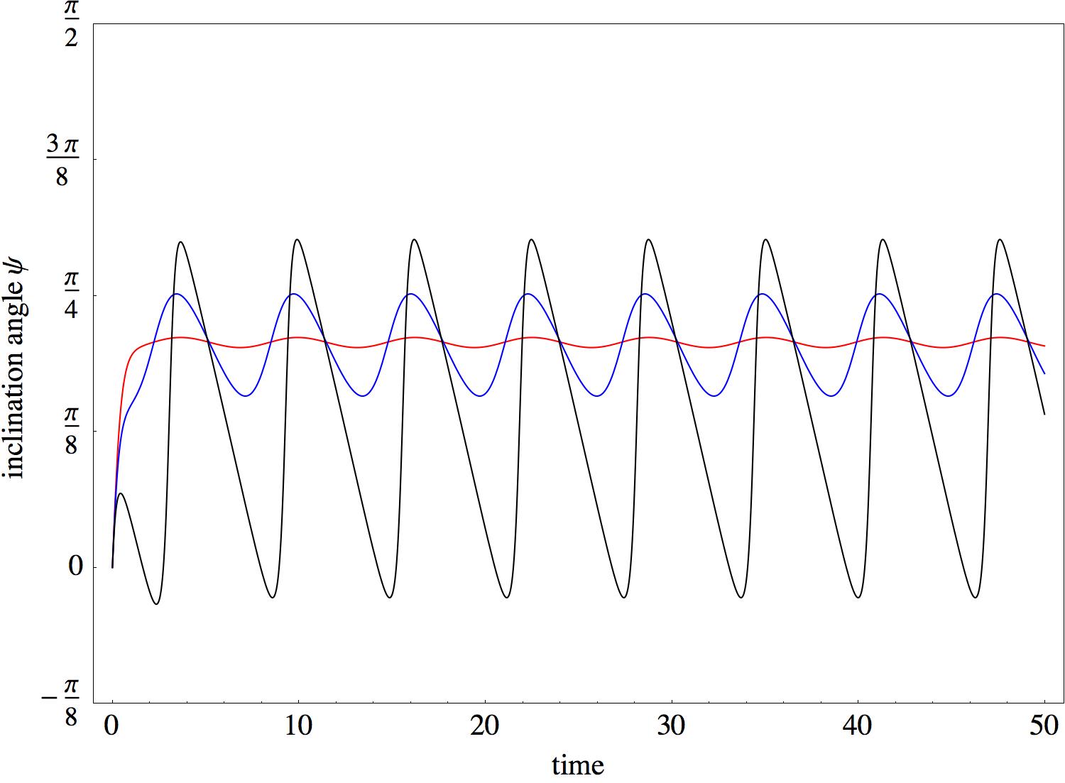
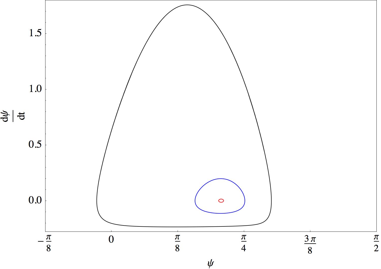
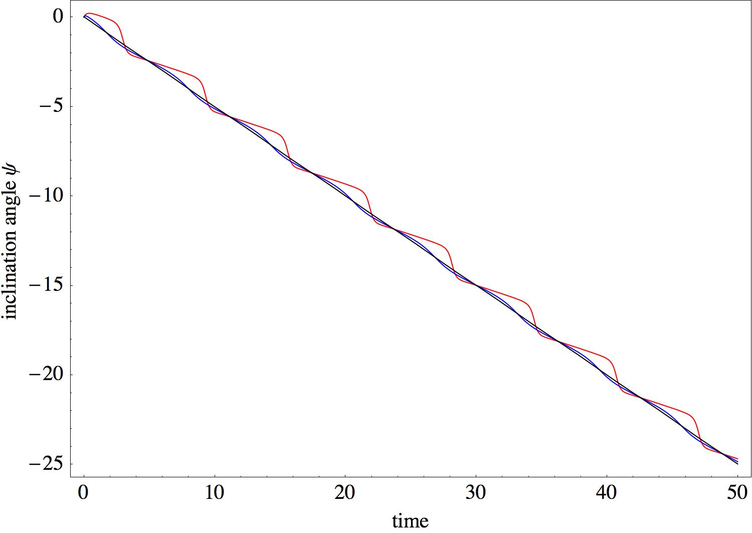
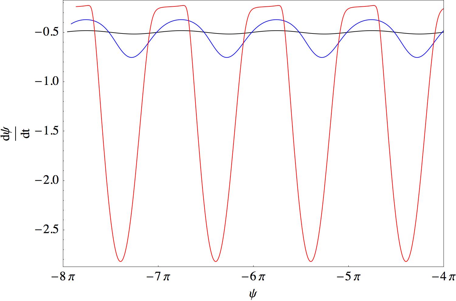
Examples of the angle evolution are shown in Figures 2-6. At high shear rates (small ), the particle is swinging; the inclination angle oscillates around a positive value as shown in Figure 2.a. Eq.(34) has a stable limit cycle as seen in Figure 2.b. As the shear rate decreases ( increases) the amplitude of the oscillations increase and the radius of the limit cycle also increases. Eventually the limit cycle loses stability and the particle begins to tumble. The tumbling dynamics is illustrated in Figures 3.a and 3.b. Increasing the viscosity ratio, at a fixed elasticity, also causes the limit cycle to disappear in favor of tumbling because increasing the viscosity ratio decreases the mean inclination angle. However the swinging amplitude is relatively insensitive to the viscosity ratio, as seen in Figures 4.a and 4.b.
At intermediate values of the elasticity parameter and high viscosity ratios, the particle exhibits intermittent behavior, which was first reported by Skotheim & Secomb (2007). Figures 5.a-6.c illustrate the complexity of the intermittent dynamics.
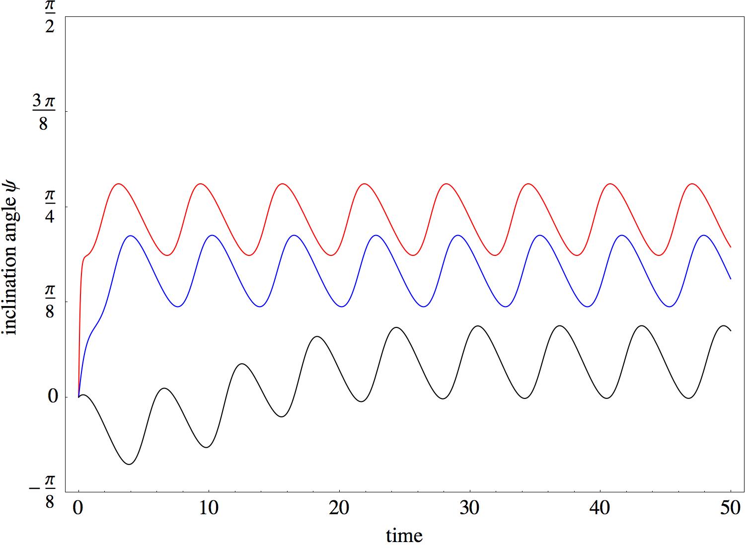
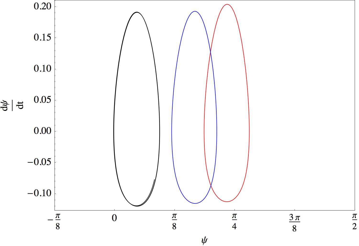
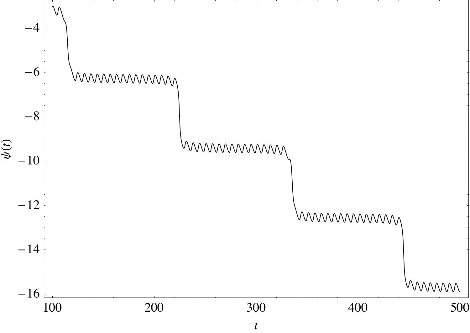
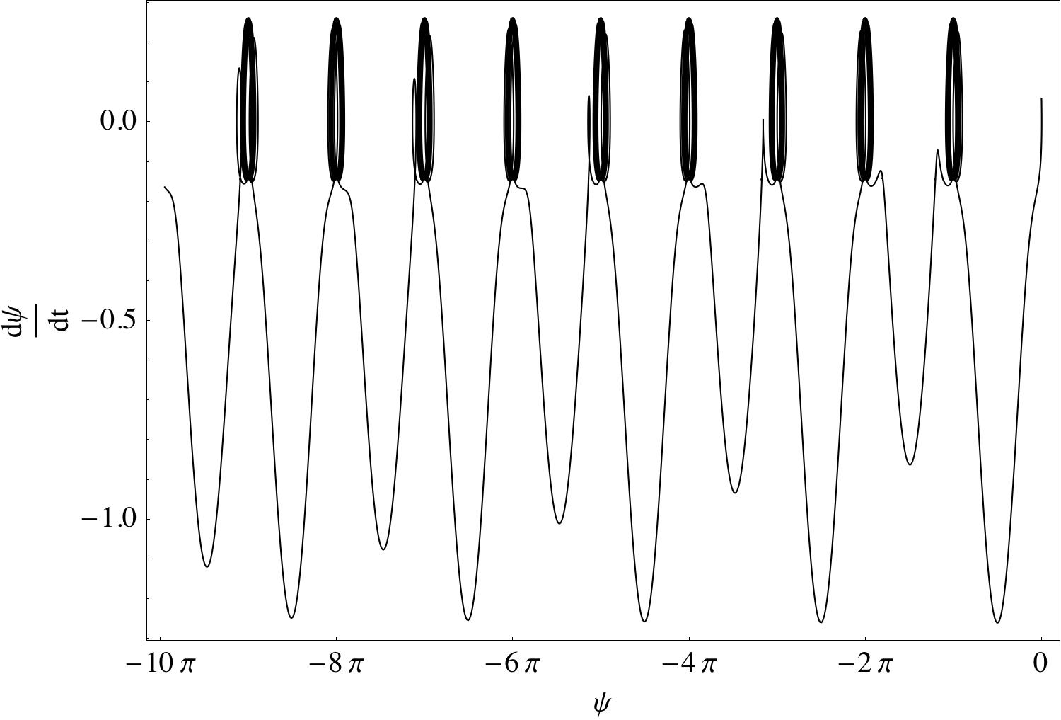
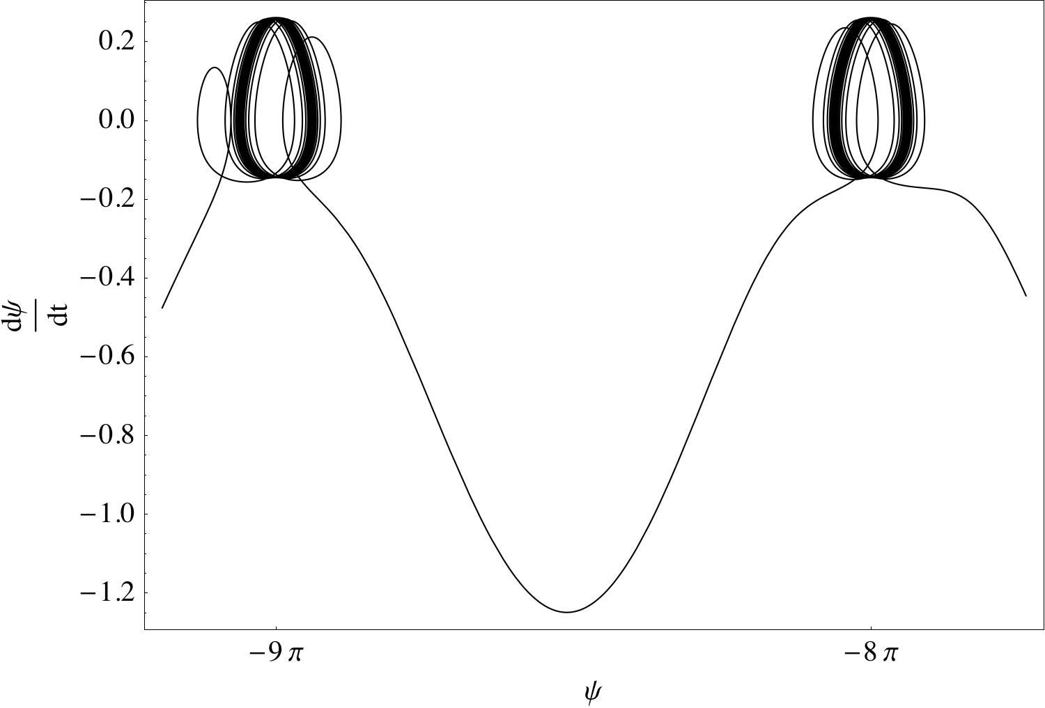
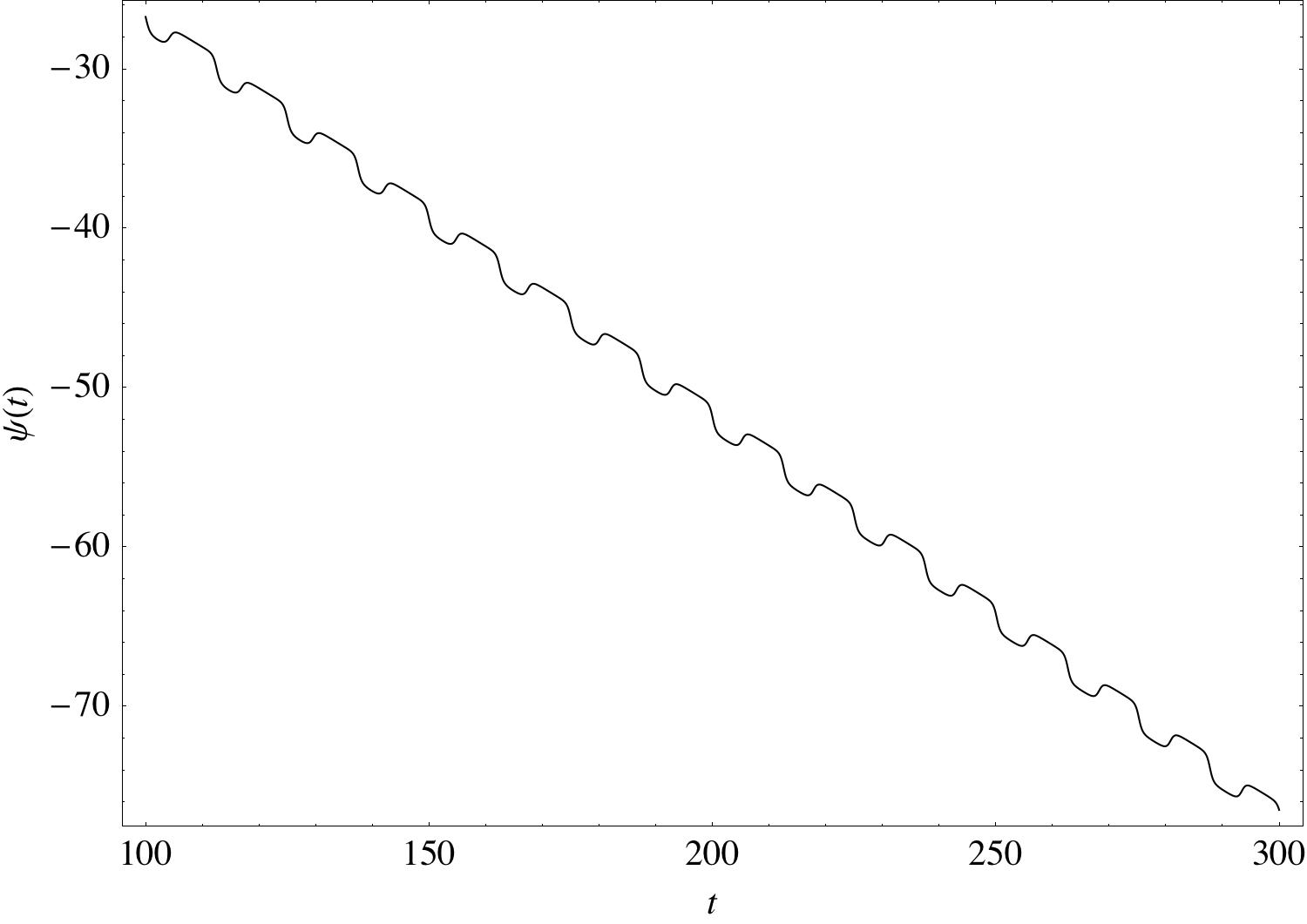
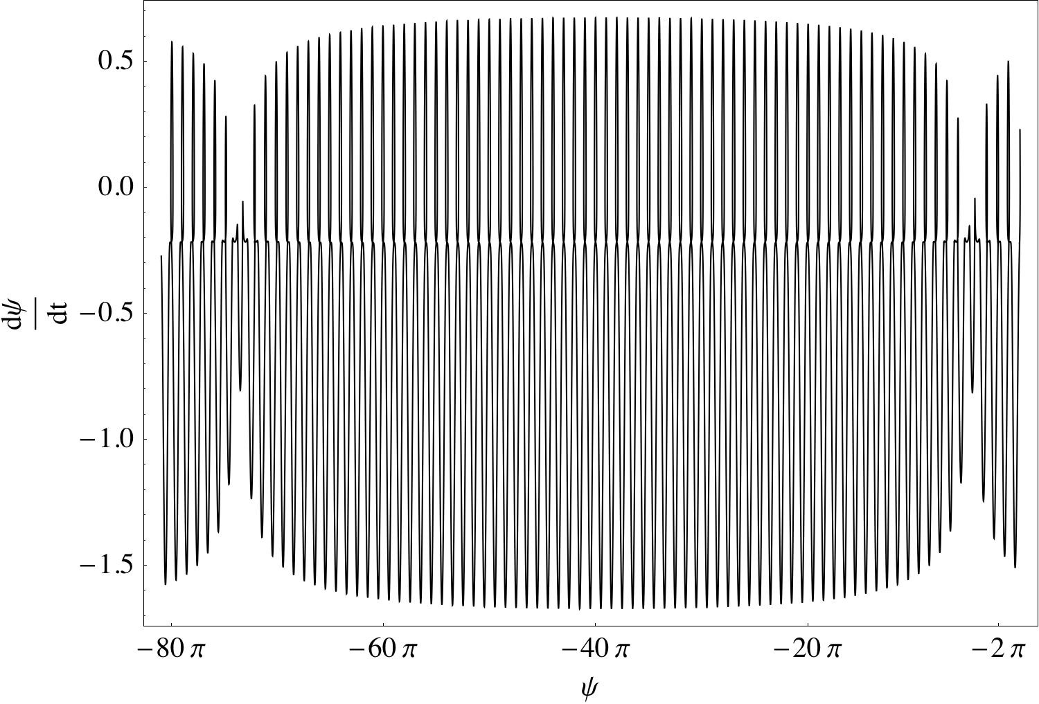
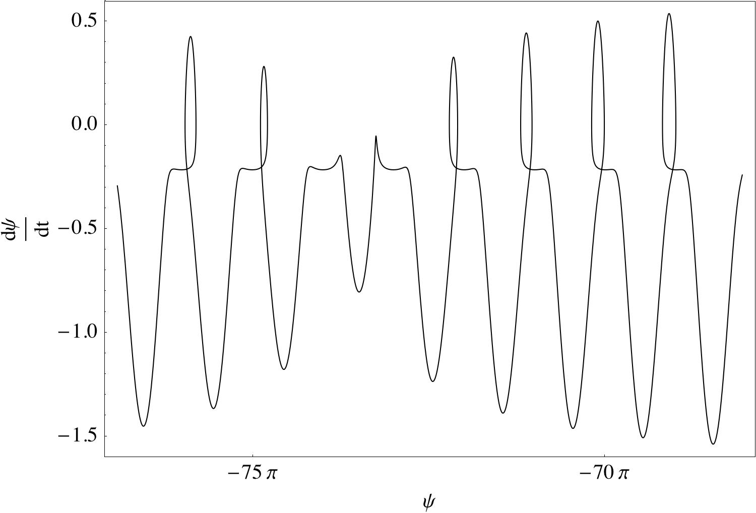
In order to compare with earlier works, we have considered an ellipsoid with excess area , which corresponds to a prolate ellipsoid with axes 0.9, 0.9 and 1. For this small excess area, the Keller-Skalak model () is in excellent agreement with the exact theory (34) and only slightly overestimates the viscosity ratio at the transition from TT to TB. However, when the elasticity is nonzero there is discrepancy between our results and those of Skotheim & Secomb (2007), mainly because it is impossible to relate their phenomenological parameter to the elastic capillary number . Our equations, however, agree with those derived by Kessler et al. (2009) (see Appendix A).
5.1.1 Phase boundary
In order to find the phase boundary between the SW and TB, the angle evolution equation (34) is rewritten as
| (35) |
where
| (36) |
At the saddle-node bifurcation from SW to TB,
Since is bounded between and , the integrand, given by (35), would be zero if
In order to estimate the critical value of the elastic capillary number , we observe that the function has a minimum when
| (37) |
At the bifurcation , which leads to (assuming that
| (38) |
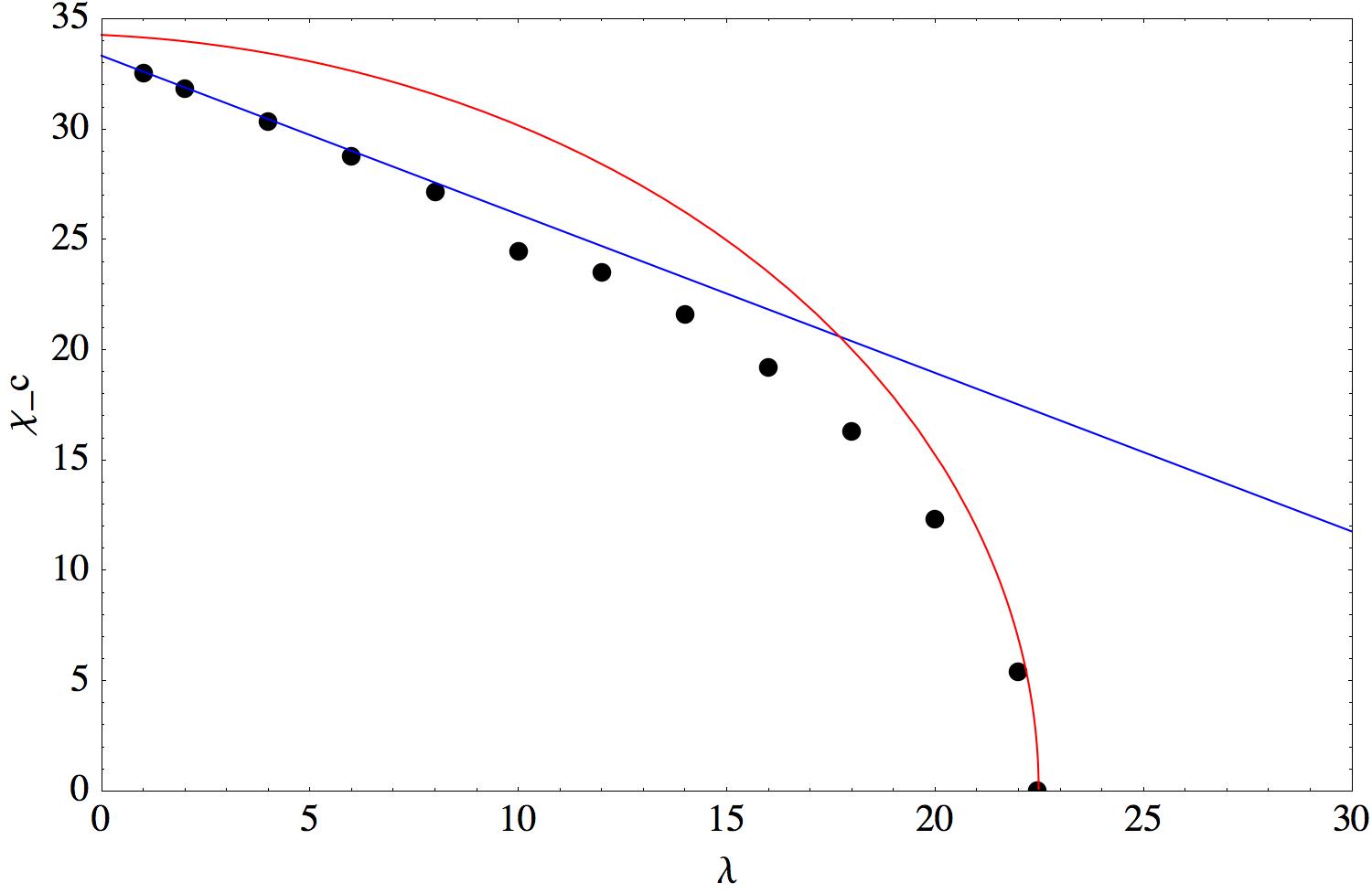
Note that the above derivation also indicates that this boundary should be an upper boundary. Figure 7 shows the phase boundary between SW and TB/intermittent dynamics.
5.1.2 Weak elasticity
In order to make further progress analytically, let us consider the limit of weak elasticity, . In this case, the effect of shear elasticity is analyzed as a small perturbation around the stationary fixed point corresponding to a tank-treading vesicle, , where . After linearization of (34) we obtain a linear forced oscillator equation
| (39) |
It can be integrated to give for the swinging motion
| (40) |
where
| (41) |
Interestingly, the phase angle does not depend on the elasticity. The amplitude of the oscillations increases linearly with the elasticity number, i.e., increases with increasing elasticity or decreasing shear rate. Also, at a given elasticity number , the oscillations decrease with viscosity ratio.
Note that the above analysis is limited to viscosity ratios such that the inclination angle is not small, i.e. . Only in this case, during the linearization we can neglect a term of the type but retain the term .
5.2 Effect of the deformability: analysis of the full system
The deformability introduces another parameter to the phase digram - the initial condition for the shape, , which measures the asphericity along the flow-vorticity direction.
In the previous section, we saw that the initial condition and imply constant and the shape is a fixed ellipsoid whose major axis lies in the plane perpendicular to the undisturbed vorticity. In the limit of high resistance to shearing , the particle motion is given by the Jeffrey orbit Jeffrey (1923) .
If but the capsule attains a stationary ellipsoid shape. In the rigid ellipsoid limit, , the motion is equivalent to the Jeffery orbit (spinning around the axis of symmetry, which is parallel to the undisturbed vorticity ); the shape is axisymmetric and characterized by and . For finite the shape is a general ellipsoid.
The most important consequence of the deformability is that it suppresses the intermittency. It appears that the intermittency is an artifact of the reduced model. Once the full set of equations (28) and (29) is solved, no intermittency is observed, only very long transients. This is in agreement with the numerical simulations by Kessler et al. (2008), and in contrast to the conclusion by Noguchi (2009) that deformability does not change qualitatively the dynamics. The latter analysis, however, ignores the effect of the tension due to the the area constraint.
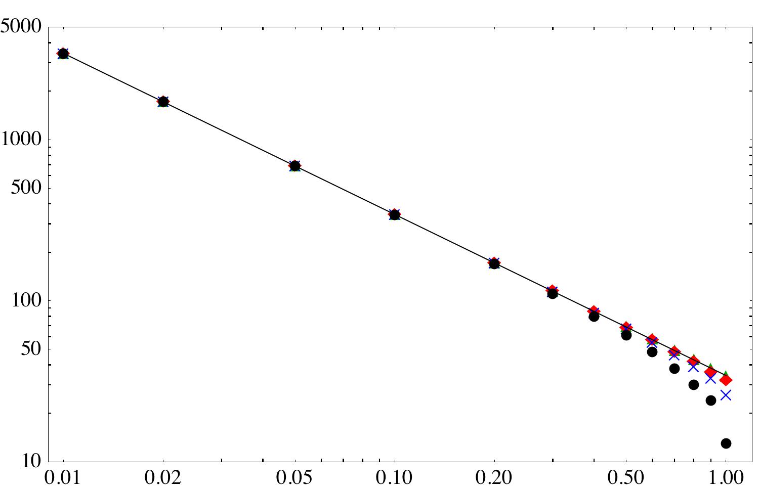
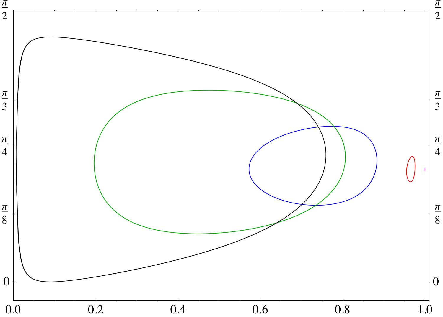
The phase diagram for a deformable particle is presented in Figures 8 and 9. Figure 8 shows that as , the critical elasticity number diverges as .
Decreasing , which allows for more deformation, widens the swinging region, as seen in Figure 9.
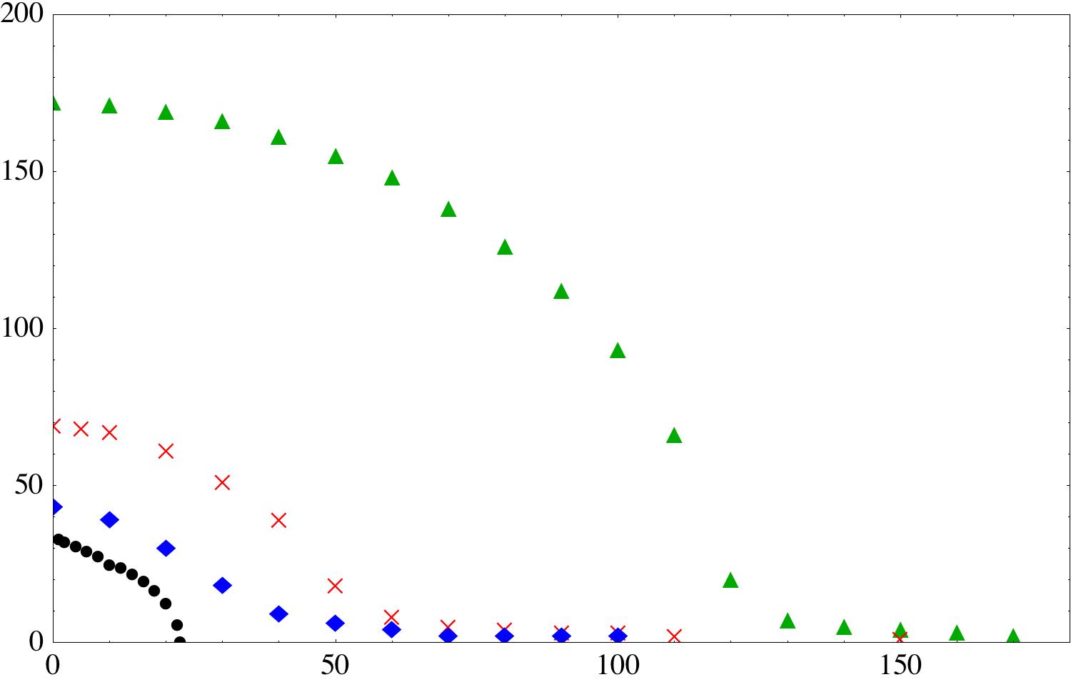
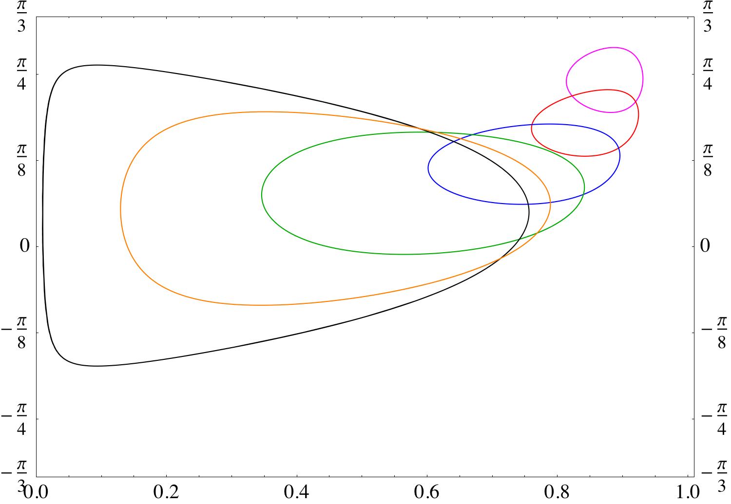
Figure 10 illustrates the evolution of the limit cycle in the phase space. The decreasing radius with increasing indicates that enhanced deformability decreases the amplitude of the oscillations.
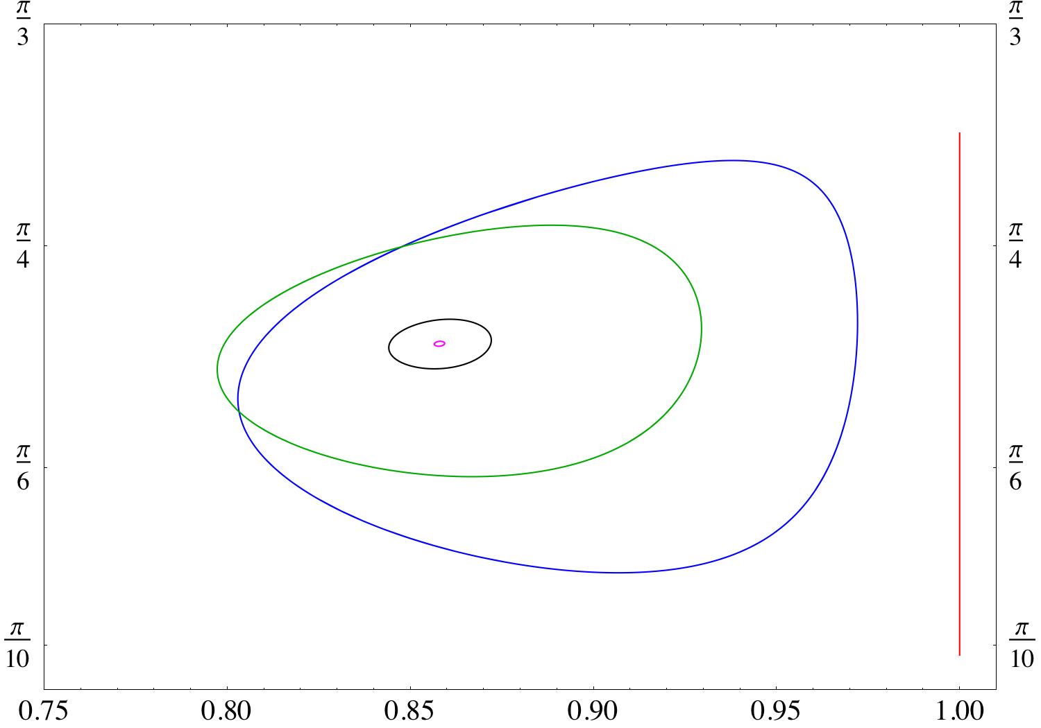
Figure 11 shows that increasing the elasticity number (decreasing the shear rate) increases the amplitude of the oscillations, and eventually causes tumbling.
Finally, Figure 12 demonstrates that increasing the viscosity ratio increases the amplitude of the oscillations.
6 Conclusions
We have considered the dynamics of a deformable membrane–encapsulated fluid particle in steady shear flow. We have developed an analytical solution in the asymptotic case where the deformation is limited by small excess area. The theory accounts for the membrane area-incompressibility, resistance to shearing, and ellipsoidal unstressed shape. The solution of the evolution equation allowed us to construct the phase diagram and to derive analytical results for the phase boundaries.
Our analysis clarifies the physical basis and limitations of earlier phenomenological models, which are restricted to fixed shape and compressible membrane. In particular, we show that the reported intermittency is an artifact of the shape-preservation.
7 Acknowledgement
PMV acknowledges partial financial support by NSF grant CBET–0846247. YNY thanks Roy Goodman for useful discussions and acknowledges financial support by NSF grants CBET–0853673 and DMS–0708977.
Appendix A Relation to the analysis of Kessler et al. (2009)
In Kessler et al.’s paper Kessler et al. (2009), angles and (not to be confused by the excess area in our notation) were employed. They are related to the inclination angle and the tank-trading angle as follows
| (42) |
Starting from their equations (21) and (22)
| (43) |
we recover our equations (28) and (29), if we identify and from their notation with
| (44) |
Performing the same analysis on (43) as in section 5.1.1 yields the phase boundary reported by Kessler et al., namely
| (45) |
Appendix B Shape evolution equations for the deformation of an ellipsoidal particle in shear flow
Ellipsoidal deformation is characterized by only modes. Let us introduce and ; same for the
The shape evolution is described by
| (46) |
| (47) |
| (48) |
| (49) |
Next we describe the solution.
Appendix C Formalism
C.1 Velocity fields and hydrodynamics stresses
Velocity fields are described using basis sets of fundamental solutions of the Stokes equations Schmitz & Felderhof (1982); Cichocki et al. (1988); Vlahovska et al. (2009a), , defined in Appendix F:
| (50a) | |||
| (50b) |
On a sphere and the velocity fields given by (50) are continuous.
The hydrodynamic tractions exerted on a surface with a normal vector are . They are expanded in vector spherical harmonics (86)
| (51) |
In the particular case of a sphere characterized with a normal vector , the amplitudes of the viscous tractions and the velocity field are linearly related
| (52a) | |||
| (52b) |
where are obtained from the velocity fields (87)–(88) Bławzdziewicz et al. (2000),
| (53) |
| (54) |
C.2 Boundary conditions: Stress balance
The stress balance in terms of spherical harmonics reads
| (55) |
Tangential stresses correspond to the components, and the normal stresses - to . The hydrodynamic tractions are given by (52b). The membrane tractions are Vlahovska & Gracia (2007); Seifert (1999)
| (56) |
where the bending stresses are
| (57) |
and the stresses due to membrane tension are
| (58) |
Note that the membrane tension is non-uniform under non-equilibrium conditions
| (59) |
The surface elastic stresses have only in-plane shearing component
| (60) |
where denotes the reference configuration. Membrane stresses do not involve a component.
Appendix D Solution
D.1 External flow
Simple shear flow is defined as
| (61) |
which translates into
| (62) |
| (63) |
D.2 Rotation: tank-treading frequency
First, we find the velocity field amplitude using the tangential stress balance with
| (64) |
This gives
| (65) |
The imposed shear flow (63) has a rotational component only with and hence the above relation reduces to
| (66) |
i.e., the rigid body rotation is unperturbed by the particle, and the particle rotates with the same rate as the flow.
D.3 Membrane incompressibility
D.4 Tension
The non-uniform part of the membrane tension, , is determined from the tangential component of the stress balance (55), ,
| (69) |
D.5 Normal velocity and shape evolution
The tension (69) is substituted into the normal component of the stress balance (55), , to obtain the normal velocity
| (70) |
where
| (71) |
and
| (72) |
Finally, the motion of the interface is determined from the kinematic condition
| (73) |
where . At leading order, it takes the form
| (74) |
is the local rate of rotation. Note that is in fact the Jaumann derivative. Substituting in (73) yields the evolution equation for the shape parameters
| (75) |
where
| (76) |
| (77) |
| (78) |
The reference configuration simply rotates with the flow
| (79) |
D.6 Isotropic tension
The normal velocity (70) and the shape evolution (75) include the yet unknown isotropic membrane tension. It is expressed in terms of the shape modes and other known parameters in the problem using the area constraint Vlahovska & Gracia (2007)
| (80) |
Since , it follows that
| (81) |
Using (75) leads to
| (82) |
In order to clarify the physical significance of the isotropic tension, let us consider the particular case when only the ellipsoidal deformation modes, , are present. (69) simplifies to
| (83) |
We see that the tension varies with deformation.
Appendix E Spherical harmonics
A good reference on spherical harmonics is Varshalovich et al. (1988). The normalized spherical scalar harmonics are defined as
| (84) |
where , are the spherical coordinates, and are the Legendre polynomials. For example
| (85) |
The vector spherical harmonics are defined as Bławzdziewicz et al. (2000)
| (86) |
where denotes the angular part of the gradient operator.
Appendix F Fundamental set of velocity fields
We reproduce the velocity and stress fields from Vlahovska & Gracia (2007). First we list the expressions for the functions . The velocity field outside the vesicle is described by
| (87a) | |||
| (87b) | |||
| (87c) |
The velocity field inside the vesicle is described by
| (88a) | |||
| (88b) | |||
| (88c) |
On a sphere these velocity fields reduce to the vector spherical harmonics defined by (86)
| (89) |
Hence, and are tangential, and is normal to a sphere. In addition, defines an irrotational velocity field.
References
- Abkarian et al. (2007) Abkarian, M., Faivre, M. & Viallat, A. 2007 Swinging of red blood cells under shear flow. Phys. Rev. Lett. 98, 188302.
- Abkarian & Viallat (2008) Abkarian, M. & Viallat, A. 2008 Vesicles and red blood cells in shear flow. Soft Matter 4, 653–657.
- Bagchi & Kalluri (2009) Bagchi, P. & Kalluri, R. M. 2009 Dynamics of nonspherical capsules in shear flow. Phys. Rev. E 80, 016307.
- Barthes-Biesel (1980) Barthes-Biesel, D. 1980 Motion of a spherical microcapsule freely suspended in a linear shear flow. J. Fluid Mech. 100, 831–853.
- Barthes-Biesel (1991) Barthes-Biesel, D. 1991 Role of interfacial properties on the motion and deformation of capsules in shear flow. Physica A 172, 103–124.
- Barthes-Biesel & Rallison (1981) Barthes-Biesel, D. & Rallison, J. M. 1981 The time–dependent deformation of a capsule freely suspended in a linear shear flow. J. Fluid Mech. 113, 251–267.
- Barthes-Biesel & Sgaier (1985) Barthes-Biesel, D. & Sgaier, H. 1985 Role of membrane viscosity in the orientation and deformation of a spherical capsule suspended in shear flow. J. Fluid. Mech. 160, 119–135.
- Bławzdziewicz et al. (2000) Bławzdziewicz, J., Vlahovska, P. & Loewenberg, M. 2000 Rheology of a dilute emulsion of surfactant-covered spherical drops. Physica A 276, 50–80.
- Cichocki et al. (1988) Cichocki, B., Felderhof, B. U. & Schmitz, R. 1988 Hydrodynamic interactions between two spherical particles. PhysicoChem. Hyd. 10, 383–403.
- Danker et al. (2007) Danker, G., Biben, T., Podgorski, T., Verdier, C. & Misbah, C. 2007 Dynamics and rheology of a dilute suspension of vesicles: higher order theory. Phys. Rev. E 76, 041905.
- Deschamps et al. (2009a) Deschamps, J., Kantsler, V., Segre, E. & Steinberg, V. 2009a Dynamics of a vesicle in general flow. PNAS 106, 11444–11447.
- Deschamps et al. (2009b) Deschamps, J., Kantsler, V. & Steinberg, V. 2009b Phase diagram of single vesicle dynamical states in shear flow. Phys. Rev. Lett. 102.
- Dimova et al. (2006) Dimova, R., Aranda, S., Bezlyepkina, N., Nikolov, V., Riske, K. A. & Lipowsky, R. 2006 A practical guide to giant vesicles. probing the membrane nanoregime via optical microscopy. J. Phys. Cond. Matt. 18, S1151–S1176.
- Edwards et al. (1991) Edwards, D. A., Brenner, H. & Wasan, D. T. 1991 Interfacial Transport Processes and Rheology. Boston: Butterworth-Heinemann.
- Erni et al. (2005) Erni, P., Fischer, P. & Windhab, E. 2005 Deformation of single emulsion drops covered with a viscoelastic adsorbed protein layer in simple shear flow. Appl. Phys. Lett. 87, 244104.
- Guido & Tomaiuolo (2009) Guido, S. & Tomaiuolo, G. 2009 Microconfined flow behavior of red blood cells in vitro. Comptes Rendus Physique 10, 751–763.
- Jeffrey (1923) Jeffrey, G. 1923 The motion of ellipsoid particles immersed in a viscous fluid. Proc. R. Soc. Lond. A 102, 169–179.
- Kantsler & Steinberg (2005) Kantsler, V. & Steinberg, V. 2005 Orientation and dynamics of a vesicle in tank-treading motion in shear flow. Phys. Rev. Lett. 95, 258101.
- Kantsler & Steinberg (2006) Kantsler, V. & Steinberg, V. 2006 Transition to tumbling and two regimes of tumbling motion of a vesicle in shear flow. Phys. Rev. Lett. 96, 036001.
- Kaoui et al. (2009) Kaoui, B., Farutin, A. & Misbah, C. 2009 Vesicles under simple shear flow: Elucidating the role of relevant control parameters. Phys. Rev. E 80, 061905.
- Keller & Skalak (1982) Keller, S. R. & Skalak, R. 1982 Motion of a tank -reading ellipsoidal particle in shear flow. J. Fluid Mech. 120, 27–47.
- Kessler et al. (2008) Kessler, S., Finken, R. & Seifert, U. 2008 Swinging and tumbling of elastic capsules in shear flow. J. Fluid Mech. 605, 207–226.
- Kessler et al. (2009) Kessler, S., Finken, R. & Seifert, U. 2009 Elastic capsules in shear flow: Analytical solutions for constant and time-dependent shear rates. Eur. Phys. J. E 29, 399–413.
- Lebedev et al. (2008) Lebedev, V. V., Turitsyn, K. S. & Vergeles, S. S. 2008 Nearly spherical vesicles in an external flow. New J. Phys. 10, 043044.
- Mader et al. (2006) Mader, M.-A., Vitkova, V., Abkarian, M., Viallat, A. & Podgorski, T. 2006 Dynamics of viscous vesicles in shear flow. Eur. Phys. J. E 19, 389–397.
- Misbah (2006) Misbah, C. 2006 Vacillating breathing and tumbling of vesicles under shear flow. Phys. Rev. Lett. 96, 028104.
- Navot (1998) Navot, Y. 1998 Elastic membranes in viscous shear flow. Phys. Fluids 10, 1819–1833.
- Noguchi (2009) Noguchi, H. 2009 Swinging and synchronized rotations of red blood cells in simple shear flow. Phys. Rev. E 80, 021902.
- Olla (2000) Olla, P. 2000 The behavior of closed inextensible membranes in linear and quadratic shear flows. Physica A 278, 87–106.
- Pozrikidis (2003) Pozrikidis, C. 2003 Modeling and Simulation of Capsules and Biological Cells. CRC Press.
- Ramanjuan & Pozrikidis (1998) Ramanjuan, S. & Pozrikidis, C. 1998 Deformation of liquid capsules enclosed by elastic membranes in shear flow: large deformations and effect of fluid viscosities. J. Fluid Mech. 117–143, 361.
- Schmitz & Felderhof (1982) Schmitz, R. & Felderhof, B. U. 1982 Creeping flow about a spherical particle. Physica A 113, 90–102.
- Schwalbe et al. (2010) Schwalbe, J., Vlahovska, P. M. & Miksis, M. 2010 Monolayer slip effects on the dynamics of a lipid bilayer vesicle in a viscous flow. J. Fluid Mech. 647, 403–419.
- Seifert (1997) Seifert, U. 1997 Configurations of fluid membranes and vesicles. Advances in physics 46, 13–137.
- Seifert (1999) Seifert, U. 1999 Fluid membranes in hydrodynamic flow fields: Formalism and an application to fluctuating quasispherical vesicles. Eur. Phys. J. B 8, 405–415.
- Skotheim & Secomb (2007) Skotheim, J. M. & Secomb, T. W. 2007 Red blood cells and other nonspherical capsules in shear flow: Oscillatory dynamics and the tank-treading-to-tumbling transition. Phys. Rev. Lett. 98, 078301.
- Sui et al. (2008) Sui, Y., Chew, Y. T., Roy, P., Cheng, Y. P. & Low, H. T. 2008 Dynamic motion of red blood cells in simple shear flow. Phys. Fluids 20, 112106.
- Varshalovich et al. (1988) Varshalovich, D. A., Moskalev, A. N. & Kheronskii, V. K. 1988 Quantum Theory of Angular Momentum. Singapore: World Scientfic.
- Vlahovska et al. (2009a) Vlahovska, P., Bławzdziewicz, J. & Loewenberg, M. 2009a Small-deformation theory for a surfactant-covered drop in linear flows. J. Fluid Mech. 624, 293–337.
- Vlahovska & Gracia (2007) Vlahovska, P. M. & Gracia, R. 2007 Dynamics of a viscous vesicle in linear flows. Phys. Rev. E 75, 016313.
- Vlahovska et al. (2009b) Vlahovska, P. M., Podgorski, T. & Misbah, C. 2009b Vesicles and red blood cells in flow: From individual dynamics to rheology. Comptes Rendus Physique 10, 775–789.
- Walter et al. (2001) Walter, A., Rehage, H. & Leonhard, H. 2001 Shear induced deformation of microcapsules: shape oscialltions and membrane folding. Coll. Surf. A 183-185, 123–132.