Mapping spin-orbit splitting in strained InGaAs epilayers
Abstract
Time- and spatially-resolved Faraday rotation spectroscopy is used to measure the magnitude and direction of the momentum-dependent spin splitting in strained InGaAs epilayers. The epilayers are lattice-matched to the GaAs substrate and designed to reduce inhomogeneous effects related to strain relaxation. Measurements of momentum-dependent spin splitting as a function of electron spin drift velocity along [100], [010], [110] and [10] directions enable separation of isotropic and anisotropic effective magnetic fields that arise from uniaxial and biaxial strain along 110. We relate our findings to previous measurements and theoretical predictions of spin splitting for inversion symmetry breaking in bulk strained semiconductors.
pacs:
71.70.Ej, 71.70.Fk, 72.25.Dc, 72.25.RbThe polarization and coherent manipulation of electron spins are important steps towards the realization of spin-based information processing wolf01 . While electron spins can be manipulated by magnetic fields, electrical control is desirable as it offers the potential for high-speed manipulation and local gates. Spin-orbit interactions in semiconductors offer momentum-dependent effective magnetic fields that can be used for electrical control datta ; physics .
Momentum k-dependent spin splittings arise from the spin-orbit interaction and the breaking of spatial inversion symmetry. The lack of an inversion center in zincblende crystal structures results in a bulk inversion asymmetry (BIA) and the Dresselhaus field dresselhaus . Structural inversion asymmetry (SIA) along the growth direction in heterostructures results in the Rashba field rashba . These internal effective magnetic fields have different k-dependence and can be distinguished by changing the direction of the carrier drift momentum. Measurements as a function of electric field direction have mapped the k-linear Rashba and Dresselhaus fields in quantum wells meier .
Strain breaks spatial inversion symmetry, which results in additional k-dependent spin splittings opticalorientation ; larocca ; bernevig . Strain-induced spin precession and characterization of k-linear spin splitting have been conducted in lattice-mismatched heterostructures kato04 and using a mechanical vise crooker05 ; beck ; sih06 . Measurements on lattice-mismatched heterostructures observed both BIA- and SIA-type splitting, but the splitting did not exhibit a clear trend as a function of measured strain kato04 . A subsequent theoretical analysis proposed that variations in strain relaxation during growth could result in different k-linear BIA-type splitting bernevig . Measurements conducted using a mechanical vise found that uniaxial strain along 110 introduces a SIA-type splitting crooker05 ; beck .
In this paper we investigate the momentum dependence of strain-induced spin-orbit splittings in In0.04Ga0.96As epilayers. The InGaAs epilayers are grown on GaAs substrates, which introduces biaxial compressive strain, and the sample structure was designed to reduce inhomogeneous effects related to strain relaxation. Measurements of internal effective magnetic fields as a function of electron spin drift velocity along [100], [010], [110] and [10] enable separation of BIA and SIA-type spin splittings that arise from biaxial and uniaxial strain.
For k in the plane perpendicular to the growth direction [001], the spin-splitting Hamiltonians take the form:
| (1) |
| (2) |
| (3) |
| (4) |
HD and HR are the Dresselhaus and Rashba Hamiltonians, respectively, while H1 and H2 are two additional k-linear terms due to strain opticalorientation ; larocca ; bernevig . Here , , and denote the [100], [010], and [001] crystal axes, denotes the Pauli matrix, are the components of the strain tensor with and , and , , , and are material constants. HR and H2 have the same direction dependence on momentum, while H1 has the same form as the linear Dresselhaus field for a two-dimensional system with quantum confinement along [001] winkler . H2 accounts for the spin splitting introduced by uniaxial strain along 110 crooker05 ; beck ; hruska , and H1 has been proposed bernevig to explain the BIA-type splitting in Ref. [kato04, ], despite earlier work opticalorientation that argued that H1 should be small. The directions of the SIA-type (HR and H2) and BIA-type (HD and H1) fields are shown in Fig. 1(b). For k along [110] and [10], the SIA and BIA fields are both perpendicular to k and parallel to each other, while for k along [100] and [010], the BIA fields are parallel to k while the SIA fields are perpendicular to k.
In general, HD is cubic in k while HR, H1, and H2 are linear in k. Thus the spin splitting can be described by combinations of k-linear and k-cubic terms of the form , where is the in-plane drift velocity defined by with the conduction band electron effective mass and the drift momentum. Yet along the [010] axis, = 0 and = k, so HD = 0 for bulk systems. Similarly, HD = 0 for k along [100]. On the other hand, for momentum along [110], , and HD reduces to HD .
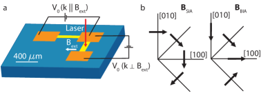
The momentum-dependent effective magnetic fields described above were measured using pump-probe optical techniques. Optical orientation of electron spins results in an out-of-plane spin polarization, which can precess about in-plane internal and applied external magnetic fields. Measurements were performed on Si-doped In0.04Ga0.96As epilayers (doping concentration = cm-3). The thickness of the InGaAs layer is 500 nm, grown above a 300 nm growth interrupted GaAs buffer layer on a (001) GaAs substrate and capped with 100 nm undoped GaAs. X-ray diffraction measurements show that the InGaAs epilayer is lattice-matched to the GaAs substrate and exhibits minimal strain relaxation. Samples were fabricated, consisting of two perpendicular InGaAs channels [Fig. 1(a)]. Channels were aligned along [110], [10], [100] and [010]. The channels were each 400 m long and 100 m wide with 400 x 400 m2 ohmic contacts at each end. Wires were soldered to each of the contacts and connected to an external voltage source. The samples were mounted in a liquid helium flow cryostat with measurements made at temperature = 30 K. Care was taken during sample mounting to minimize introducing additional strain.
Measurements were conducted using a mode-locked Ti:Sapphire laser with a repetition rate of 76 MHz tuned to the band edge of the InGaAs epilayer ( = 848 nm). The laser was separated into a pump and probe pulse with a temporal separation controlled by a mechanical delay line. The pump and probe beams were modulated by a photoelastic modulator (PEM) and optical chopper respectively for cascaded lock-in detection. An external magnetic field was applied in the plane of the layer and varied from -40 to 40 mT. The inclusion of a motor driven steering mirror in the pump path allowed control of the pump-probe spatial separation on the sample. Field scans were taken at 5 m intervals over a 40 m range (roughly 20 m from the center of the electron spin packet). By applying an external voltage to the contacts, the electron drift momentum was varied along each channel. Measurements were performed with the channels oriented both parallel with and perpendicular to the applied magnetic field to measure both the magnitude and direction of the internal magnetic fields.
Faraday rotation (FR) of the probe pulse can be described by:
| (5) |
where is the FR amplitude, g is the electron g factor, is the Bohr magneton, is the inhomogeneous dephasing time, t is the pump-probe time delay, and Bext is the applied external magnetic field. Time-resolved FR measurements crooker find that g = 0.51 and = 7.8 ns. The direction and magnitude of the internal magnetic field Bint, which is proportional to the spin splitting = , is determined from fits of the FR signal to Eq. 5 with errors less than 1. As shown in Fig. 2(a), the component of Bint that is parallel to Bext causes an overall shift in the field-dependent signal, and the component that is perpendicular to Bext changes the magnitude of the center peak. B∥ (B⟂) is defined as the component of Bint that is parallel (perpendicular) to , as determined from field scans based on the channel orientation. Measurements were taken with k Bext and k Bext to determine both the sign and magnitude of the spin splitting. The magnitude of the drift momentum was varied by changing the potential applied to the channels, in the range between -2.0V and 2.0V. Scans with varying pump-probe spatial separations were taken to characterize the internal field and drift velocity of the optically injected spin packet [Fig. 2]. The drift velocity of the spin packet at each voltage is the measured spatial drift of the spin packet center during the pump-probe time delay ns.

For the [010] channel oriented perpendicular to the external magnetic field, values of B⟂ and B∥ are displayed for various contact voltages as a function of pump-probe spatial separation in Fig. 3. The amplitude of the FR is also fit for each scan to determine the position of the spin packet center at each voltage [Fig. 3(c)]. The spatial dependence of Bint is due to both drift and diffusion of the spin packet kato04 . For the [010] channel, it is expected that Bint has a linear dependence on k because HD = 0. For each voltage, a linear fit is used to determine the value of Bint at . These values are fit to linear functions of [Fig. 3(d)] to determine the values of and .
| Channel | / | / | / | / | ||||
| [100] | 35 | -84 | -230 | 47 | 35 | -110 | -300 | 47 |
| [010] | -35 | -100 | -280 | 48 | -41 | -91 | -250 | 56 |
| [110] | 0 | -14 | -180 | 70 | 0 | -20 | -150 | 50 |
| [10] | 0 | -120 | — | — | 0 | -94 | — | — |
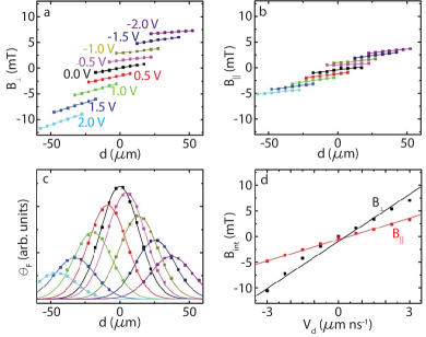
Table 1 shows a summary of the measured values of and for all four channel directions and both measurement orientations, k Bext and k Bext. All of the measurements are well described by a linear dependence of Bint with k, so = /. Measurements with k Bext and k Bext show reasonable agreement, but with noticeable discrepancies that are larger than the measurement error, which is typically on the order of 1 5 . Additional strain introduced during sample mounting and cool-down could possibly account for these discrepancies. For the [100] and [010] channels for which the SIA- and BIA-type spin splittings can be separated, we found that the SIA splitting () is consistently 2 or 3 times larger than the BIA splitting (). For the [010] channel, the value of can be attributed to HR and H2 and to H1, since H for k along [010]. Also, as expected from the form of H1 [Eq. 3], the BIA-type splitting () has similar magnitude but opposite sign for [100] and [010], which justifies the assumption that for this sample.
Although the measurements cannot distinguish between the contributions of HR and H2, previous measurements indicate that the effect of H2 is greater than that of HR for similar bulk epilayers. Measurements kato04 on unstrained n-doped GaAs epilayers found , and that the measured spin splitting upon applied strain could be characterized using H2 and without requiring HR crooker05 ; beck ; sih06 .
From Eqs. 3 and 4 and the measured values of , we calculate the sample parameters C3/ and D()/ assuming no contribution from HD and HR and vurgaftman , where m0 is the free electron mass. From the measurements on the [100] and [010] channels, C3/ has an average value of -270 m/s, and D()/ = 50 m/s. From Ref. [bernevig, ], C3/ = m/s and D/ = (0.5 - 1.5) m/s. From the literature value of C3/ and the range of values of C/ measured here, = -0.029 -0.038. Therefore, the variation in our measurements indicates that the strain changes by an amount less than between different sample mountings and cool-downs. For pseudomorphic In0.04Ga0.96As on GaAs jain , = -0.29 and = 0.26, which yields D/ = m/s, which is in the same range as previously reported values kato04 ; bernevig . The data and analysis show that the measured spin splittings are consistent with H1 and H2 and that H2 can have comparable magnitude to H1, which contradicts the argument that H1 is small and can be neglected opticalorientation ; hruska .
Unexpectedly, the values of for the [10] and [110] channels do not match the difference and sum, respectively, of the SIA and BIA terms from the other channels. Therefore, measurements along [110] and [10] may not be sufficient to accurately characterize H1 and H2. For [110], = -14 neV ns m-1 for k Bext and -20 neV ns m-1 for k Bext. These values are both smaller in magnitude than the average sum = -58 neV ns m-1 from measurements on the [100] and [010] channels. Similarly, for [10], = -120 neV ns m-1 for k Bext and -94 neV ns m-1 for k Bext, and both values are smaller in magnitude than the average difference = -130 neV ns m-1. We also calculate C3/ and D()/ assuming that H1 and H2 and obtain a smaller value for C3/. The calculated C3/ and D()/ values are included in Table 1. We hypothesize that higher order terms, including the additional k-cubic Dresselhaus term (HD) for [110] and [10], could account for this discrepancy.
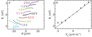
We also observe unexpected behavior in the measured slope of Bint as a function of pump-probe spatial separation and voltage for the [110] channel. The slope of Bint at each voltage is due to diffusion and the distribution of drift velocity of the spin packet from the finite spot size ( 30 x 10 m) of the pump and probe beams kato04 . Electrons at the leading edge of the packet have a higher average velocity than those in the back and thus we expect a non-zero and positive slope. However, as shown in Fig. 4(a), for scans in the voltage range 1.0 - 2.0V for the [110] sample, surprisingly, a negative slope is observed. This was found from repeated measurements on different spots along the channel and is therefore not thought to be a result of any interface reflection effects. The measurements of do not seem to be affected, as the value for Bint for the center of the spin packet at each voltage still has a linear dependence on spin drift velocity, as shown in Fig. 4(b). Measurements for both configurations k Bext and k Bext show reasonable agreement, with values for of -14 and -20 neV ns m-1, respectively. The smaller spin splitting could possibly explain why this behavior is only apparent in the [110] sample. Larger values of could overwhelm this effect in other channels.
This material is based upon work supported by the National Science Foundation under Grants No. ECCS-0844908 and DMR-0801388 and the Horace H. Rackham School of Graduate Studies. Sample fabrication was performed in the Lurie Nanofabrication Facility, part of the NSF funded NNIN network.
References
- (1) S. A. Wolf, D. D. Awschalom, R. A. Buhrman, J. M. Daughton, S. von Molnar, M. L. Roukes, A. Y. Chtchelkanova, and D. M. Treger, Science 294, 1488 (2001).
- (2) S. Datta and B. Das, Appl. Phys. Lett. 56, 665 (1990).
- (3) D. Awschalom and N. Samarth, Physics 2, 50 (2009).
- (4) G. Dresselhaus, Phys. Rev. 100, 580 (1955).
- (5) Y. A. Bychkov and E. I. Rashba, J. Phys. C 17, 6039 (1984).
- (6) L. Meier, G. Salis, I. Shorubalko, E. Gini, S. Schon, and K. Ensslin, Nature Physics 3, 650 (2007).
- (7) G. E. Pikus and A. N. Titkov, in Optical Orientation, edited by F. Meier and B. P. Zakharchenya (Elsevier Science Publishers, Amsterdam, 1984).
- (8) G. C. La Rocca, N. Kim, and S. Rodriguez, Phys. Rev. B 38, 7595 (1988).
- (9) B. A. Bernevig and S.-C. Zhang, Phys. Rev. B. 72, 115204 (2005).
- (10) Y. Kato, R. C. Myers, A. C. Gossard and D. D. Awschalom, Nature 427, 50 (2004).
- (11) S. A. Crooker and D. L. Smith, Phys. Rev. Lett. 94, 236601 (2005).
- (12) M. Beck, C. Metzner, S. Malzer and G. H. Dohler, Europhys. Lett. 75, 597 (2006).
- (13) V. Sih, H. Knotz, J. Stephens, V. R. Horowitz, A. C. Gossard, and D. D. Awschalom, Phys. Rev. B 73, 241316(R) (2006).
- (14) R. Winkler, Spin-Orbit Coupling Effects in Two-Dimensional Electron and Hole Systems, Springer Tracks in Modern Physics Vol. 191 (Springer, Berlin, 2003).
- (15) M. Hruska, S. Kos, S. A. Crooker, A. Saxena and D. L. Smith, Phys. Rev. B 73, 075306 (2006).
- (16) S. A. Crooker, D. D. Awschalom, J. J. Baumberg, F. Flack and N. Samarth, Phys. Rev. B 56, 7574 (1997).
- (17) I. Vurgaftman, J. R. Meyer, and L. R. Ram-Mohan, J. Appl. Phys. 89, 5815 (2001).
- (18) S. C. Jain, M. Willander, and H. Maes, Semicond. Sci. Technol. 11, 641 (1996).