Multimode nematicon waveguides
Abstract
We report on the first experimental observation of higher-order modes guided by soliton-induced waveguides in unbiased nematic liquid crystals. We find that the nematicon waveguides operate in a bounded power region specific to each guided mode. Below this region the guided beams diffract, above it the mode mixing and coupling give rise to an unstable output.
pacs:
42.25.Bs, 42.68.Mj, 92.60.TaSpatial optical solitons propagate in nonlinear Kerr-like media as modes of the self-induced waveguides Kivshar . An attractive property of soliton-induced waveguides is their ability to guide weak signals of different wavelengths Shih ; Peccianti2000 ; Petter2001 , as well as the possibility to reconfigure such waveguides by spatial steering Petter2001 ; Peccianti2001 ; Peccianti2002 ; Henninot2004 . To this extent, various schemes for all-optical processing have been reported, employing interaction of several solitons Peccianti2002 ; Peccianti2004 ; Conti2006 ; Izdebskaya_jeos , deflection by defects Pasquazi2005 ; Serak2006 ; Piccardi_2010 ; Izdebskaya_ol or patterned nonlinearity Beeckman2006 ; NP06 ; kaczmarek_inplane .
Another dimension in soliton-based optical switching is offered by the multi-modal character of self induced waveguides, observed earlier with photorefractive solitons Shih ; Petter2002 and optical vortices PiO . In this regard, the nematicon waveguides, i.e. spatial optical solitons in nematic liquid crystals Peccianti2000 ; Peccianti2001 ; Peccianti2002 ; Peccianti2004 ; Izdebskaya_jeos ; Pasquazi2005 ; Serak2006 ; Conti2006 ; Piccardi_2010 ; Izdebskaya_ol ; Beeckman2006 ; NP06 , are of particular interest, because of the long-range or highly nonlocal character of the reorientational nonlinearity. The transverse size of the nematicon-induced index perturbation can be up to one order of magnitude larger than the beam itself Conti_2004 ; Hutsebaut ; Henninot2007 and, therefore, such a waveguide is expected to be multi-moded. Additional evidence of such multimodality is the existence of higher-order nonlocal solitons 1981 ; PRL07 ; Beeckman2010 and incoherent solitons Buljan2004 ; Shen2006 , as observed in Refs. Opt.Commun ; moti05 and Mitchell1997 ; Peccianti_inco , respectively. Nevertheless, to date, the higher-order modes guided by fundamental nematicons were never observed.
In this Letter we study experimentally the multimode soliton waveguides in nematic liquid crystals, identifying the power domains where high-order guided modes are supported. These domains are limited from above, because the number of modes grows with nematicon power, whereas their mixing eventually gives rise to unstable outputs. The cell geometry and finite size sets additional limits to the order and orientation of nematicon-guided modes. Because of liquid crystal birefringence, the distinction between hybrid EH and HE modes is not possible Snyder , and we use the notation Hmn or Hermite-like modes with indices .
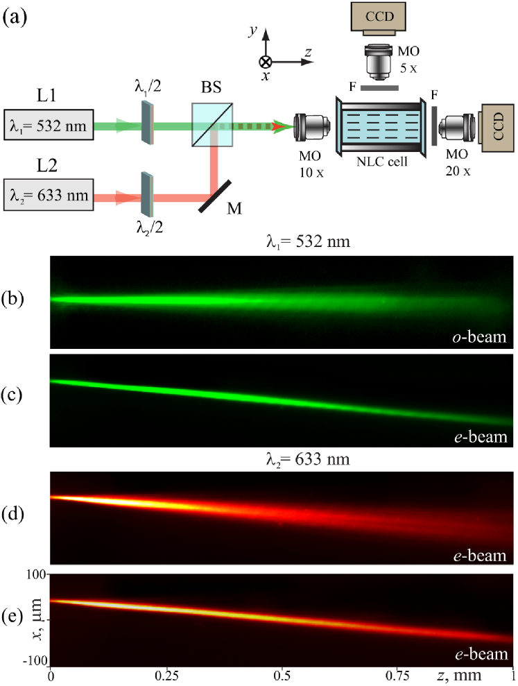
Experimental setup is shown in Fig. 1(a). We employ a planar cell with the (propagation) length of 1.1 mm, formed by two m-spaced parallel polycarbonate slides containing the 6CHBT nematic liquid crystal (NLC). The mean angular orientation of the NLC molecules (the molecular director) was pre-set by mechanically rubbing the internal interfaces at -angle with respect to in the plane, parallel to the slides. To prevent the formation of exposed menisci, two additional m-thick slides were attached perpendicularly to to seal the cell input and output. We use micro-objectives and CCD cameras to collect the light at the sample output and scattered above the cell during propagation.
Figures 1(b,c) show sample top-view photos of either ordinary (‘o’, electric field parallel to ) or extraordinary (‘e’, electric field parallel to ) polarized green beams ( nm) launched with mW input power and the wavevector aligned to . Clearly, the o-beam in Fig. 1(b) diffracts below the Freedericks threshold, whereas the e-beam in Fig. 1(c) is self-trapped while walking-off at an angle with respect to . The -signal beam (red, nm) is copolarized and launched collinearly with the green beam, resulting in either diffraction without nematicon [Fig. 1(d)], or guided-wave confinement by nematicon [Fig. 1(e)].
Noteworthy, the nematicons are generated in a uniaxial liquid medium subject to slow dynamics time and instabilities Conti2006 ; MI ; Izdebskaya_oe , where birefringence-induced walk-off is power sensitive Izdebskaya_oe ; wo3 and nonlocality leads to beam breathing Conti_2004 ; transverse . In the absence of external bias, as in our configuration Izdebskaya_jeos ; Izdebskaya_ol ; Izdebskaya_oe , these effects result in a bent non-uniform waveguide with fluctuations on a time scale smaller than the inverse maximum frame-rate of our camera (25 fps). Corresponding changes in modal profiles and the time-dependent mode mixing Snyder demand for temporal averaging of output images recorded during data acquisition, typically 40 frames at 4 fps. Therefore, we define as the beam half-widths at half-maximum (HWHM) of the averaged intensity distributions in and directions, respectively.
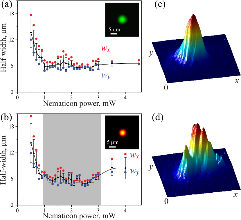
Figure 2 shows the experimental results for a green nematicon [Fig. 2(a)] and a weak red fundamental H00 mode co-launched at the input [Fig. 2(b-d)]. At low power ( mW) the self-focusing reduces the waist in the green and corresponding size of the guided mode in the red, until a nematicon is generated for mW [Fig. 2(a)] and the red signal becomes a guided mode [Fig. 2(b)]. The shaded region in Fig. 2(b) marks the existence of a stable H00 guided mode, with typical averaged output transverse profile displayed in Fig. 2(c). Further increases of nematicon power lead to a soliton waveguide supporting more guided modes, with a stronger mixing and an output signal exhibiting a multi-hump profile, as in Fig. 2(d). The latter transition for mW is accompanied by an increase in HWHM for the red signal, as apparent in Fig. 2(b), whereas the nematicon maintains its robust structure. Clearly, the nonlinear refractive index potential gets higher and wider with nematicon excitation, inducing a multi-moded channel waveguide where a complex pattern appears owing to superposition and mixing of guided modes Snyder .
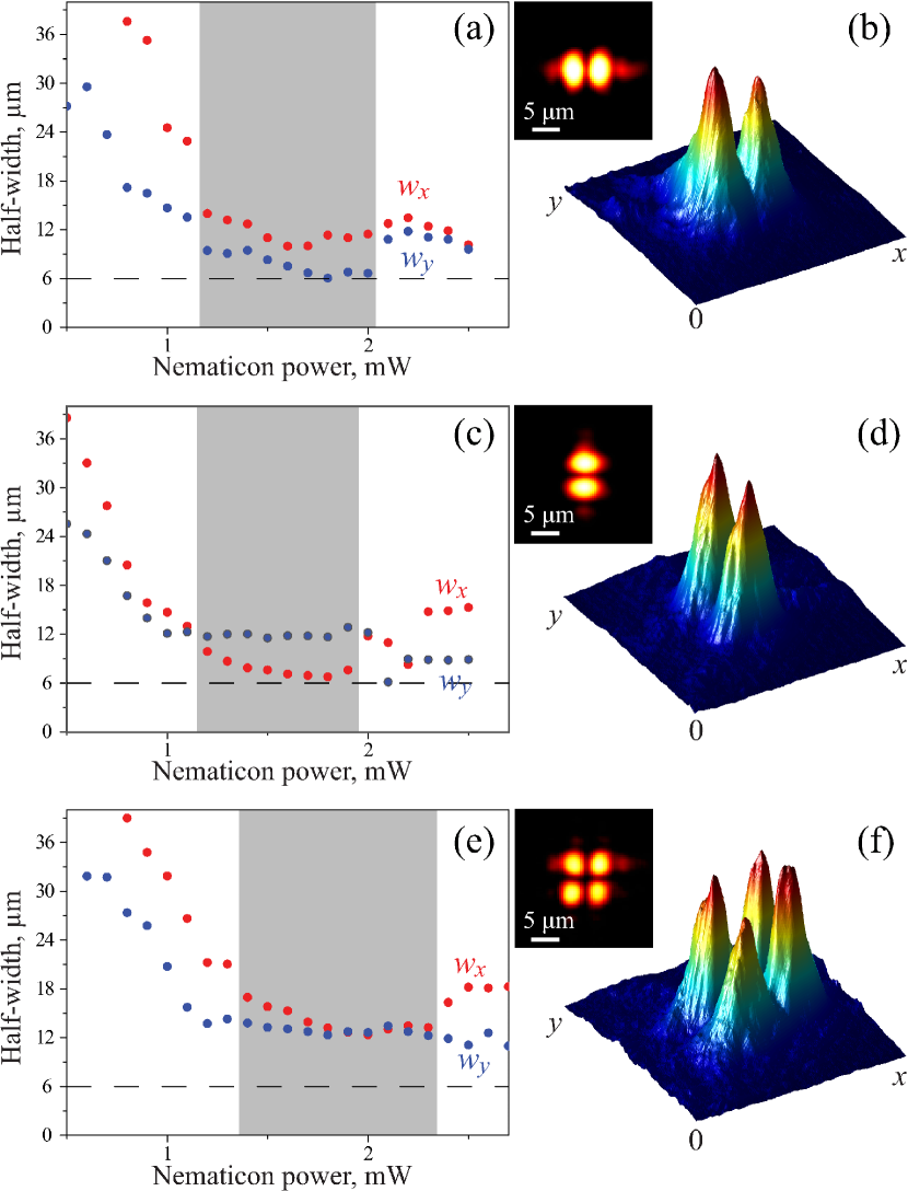
To excite the first-order mode in the soliton-induced waveguide we insert a thin glass plate in front of half of the signal beam and tilt it, introducing a -phase jump, to reproduce the phase profiles of H10 and H01 modes, see the insets in Figs. 3(a,c). The HWHM of both modes versus nematicon excitation [Figs. 3(a,c)] exhibit regions of stable guidance as in Figs. 2(a,b), with averaged profiles shown in Figs. 3(b,d)]. At variance with soliton waveguides in photorefractive crystals, subject to a directional bias Petter2002 , both dipole-like modes coexist in the same interval of excitations, , suggesting that the role of the cell boundaries and the related index anisotropy are minimal in our sample Conti_PRE . Using two glass plates we also generate and launch H11 mode of the red signal, as shown in Figs. 3(e-f). The HWHM of this mode in both and directions correspond well to the size of H10 and H01 modes above, m, approximately twice wider than the nematicon (see dashed lines). As expected, the (shaded) stable domain for H11 is shifted towards higher powers with .
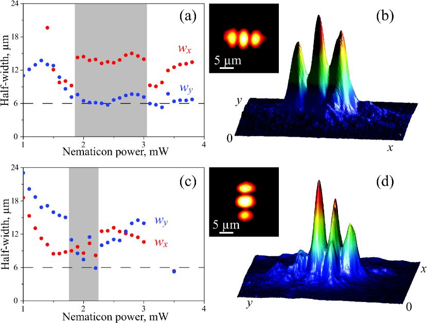
Finally, Fig. 4 shows the experimental results for H20 and H02 modes. The H20 mode displays a relatively broad domain of stable existence, . Its HWHM m is nearly three times larger than the nematicon. In sharp contrast, the vertically oriented H02 mode [Fig. 4(d)] is only stable in a narrow domain, , due to the (anisotropic) role of the cell boundaries in with fixed director orientation, and despite the fact that its total width, m, is much smaller than the cell thickness m. It follows that the order of the supported guided modes is limited from above not only by the nematicon power and mode-mixing process, but also by the boundary-induced anisotropy Conti_PRE . For Hmn with , the nematicon waveguides can be considered isotropic and circularly symmetric.
In conclusion, we have shown experimentally that the waveguides induced by spatial solitons in unbiased nematic liquid crystals can support various co-polarized guided modes. Multimode waveguides exist in well defined regions of excitations. The confinement of several guided modes in self-induced waveguides is potentially useful for soliton-based optical switches, interconnects and all-optical processing.
The authors acknowledge the Australian Research Council for financial support and thank Prof. W. Krolikowski and Dr. A. Alberucci for useful suggestions.
References
- (1) Yu. S. Kivshar and G. P. Agrawal, Optical Solitons: From Fibers to Photonic Crystals (Academic Press, San Diego, 2003).
- (2) M.-F. Shih, M. Segev, and G. Salamo, Opt. Lett. 21, 931 (1996).
- (3) M. Peccianti, G. Assanto, A. De Luca, C. Umeton, and I. C. Khoo, Appl. Phys. Lett. 77, 7 (2000).
- (4) J. Petter and C. Denz, Opt. Commun. 188, 55 (2001).
- (5) M. Peccianti and G. Assanto, Opt. Lett. 26, 1690 (2001).
- (6) M. Peccianti, K. A. Brzdkiewicz, and G. Assanto, Opt. Lett. 27, 1460 (2002).
- (7) J. F. Henninot, M. Debailleul, R. Asquini, A. d’Alessandro, and M. Warenghem, J. Opt. A 6, 315 (2004).
- (8) M. Peccianti, C. Conti, G. Assanto, A. De Luca, and C. Umeton, Nature 432, 733 (2004).
- (9) C. Conti, M. Peccianti, and G. Assanto, Opt. Lett. 31, 2030 (2006).
- (10) Ya. V. Izdebskaya, V. Shvedov, A. S. Desyatnikov, W. Krolikowski, G. Assanto, and Yu. S. Kivshar, J. Eur. Opt. Soc. Rapid Publ. 5, 10008 (2010).
- (11) A. Pasquazi, A. Alberucci, M. Peccianti, and G. Assanto, Appl. Phys. Lett. 87, 261104 (2005).
- (12) S. V. Serak, N. V. Tabiryan, M. Peccianti, and G. Assanto, IEEE Photon. Tech. Lett. 18, 1287 (2006).
- (13) A. Alberucci, A. Piccardi, U. Bortolozzo, S. Residori, and G. Assanto, Opt. Lett 35, 390 (2010).
- (14) Ya. V. Izdebskaya, V. G. Shvedov, A. S. Desyatnikov, W. Z. Krolikowski, and Yu. S. Kivshar, Opt. Lett. 35, 10 (2010).
- (15) J. Beeckman, K. Neyts, and M. Haelterman, J. Opt. A 8, 214 (2006).
- (16) M. Peccianti, A. Dyadyusha, M. Kaczmarek, and G. Assanto, Nat. Physics 2, 737 (2006).
- (17) A. Piccardi, M. Peccianti, G. Assanto, A. Dyadyusha, and M. Kaczmarek, Appl. Phys. Lett. 94, 091106 (2009).
- (18) J. Petter, C. Denz, A. Stepken, and F. Kaiser, J. Opt. Soc. Am. B 19, 1145 (2002).
- (19) A. S. Desyatnikov, Yu. S. Kivshar, and L. Torner, Prog. Opt. 47, 291 (ed. E. Wolf, North-Holland, Amsterdam, 2005).
- (20) C. Conti, M. Peccianti and G. Assanto, Phys. Rev. Lett. 92, 113902 (2004).
- (21) X. Hutsebaut, C. Cambournac, M. Haelterman, J. Beeckman, and K. Neyts, J. Opt. Soc. Am. B 22, 1424 (2005).
- (22) J. F. Henninot, J. F. Blach, and M. Warenghem, J. Opt. A 9, 20 (2007).
- (23) V. A. Mironov, A. M. Sergeev, and E. M. Sher, Sov. Phys. Dokl. 26, 861 (1981).
- (24) D. Buccoliero, A. S. Desyatnikov, W. Krolikowski, and Yu. S. Kivshar, Phys. Rev. Lett. 98, 053901 (2007).
- (25) J. Beeckman, K. Neyts, P. J. M. Vanbrabant, R. James, and F. A. Fernandez, Opt. Express 18, 3311 (2010).
- (26) H. Buljan, T. Schwartz, M. Segev, M. Soljacic, and D. N. Christodoulides, J. Opt. Soc. Am. B 21, 397 (2004).
- (27) M. Shen, J. Shi, and Q. Wang, Phys. Rev. E 74, 027601 (2006).
- (28) X. Hutsebaut, C. Cambournac, M. Haelterman, A. Adamski, and K. Neyts, Opt. Commun. 233, 211 (2004).
- (29) C. Rotschild, O. Cohen, O. Manela, M. Segev, and T. Carmon, Phys. Rev. Lett. 95, 213904 (2005).
- (30) M. Mitchell and M. Segev, Nature 387, 880 (1997).
- (31) M. Peccianti and G. Assanto, Opt. Lett. 26, 1791 (2001).
- (32) A. M. Snyder and J. D. Love, Optical Waveguide Theory (Chapmen and Hall, London, 1983).
- (33) J. Beeckman, K. Neyts, X. Hutsebaut, C. Cambournac, and M. Haelterman, IEEE J. Quantum Electron. 41, 735 (2005).
- (34) M. Peccianti, C. Conti and G. Assanto, Phys. Rev. E 68, R025602 (2003).
- (35) Ya. V. Izdebskaya, V. G. Shvedov, A. S. Desyatnikov, W. Z. Krolikowski, M. Belic, G. Assanto, and Yu. S. Kivshar, Opt. Express 18, 3258 (2010).
- (36) A. Piccardi, A. Alberucci, and G. Assanto, Appl. Phys. Lett. 96, 061105 (2010).
- (37) M. Peccianti, A. Fratalocchi, and G. Assanto, Opt. Express 12, 6524 (2004).
- (38) C. Conti, M. Peccianti, and G. Assanto, Phys. Rev. E 72, 066614 (2005).