Amplification of light in a glass ball suspended within a gainy medium
Filipp V. Ignatovich1∗ and Vladimir K. Ignatovich2
1Lumetrics Inc, 150 Lucius Gordon Dr, ste 117
West Henrietta, N.Y. 14586
2Frank Laboratory for Neutron Physics, Joint Institute for Nuclear Research,
Dubna, Russia 141980
∗Corresponding author: ifilipp@gmail.com
Abstract
We discuss total internal reflection (TIR) from an interface between glass and active gaseous media and propose an experiment for strong light amplification.
OCIS codes: 140.0140, 140.4480, 140.6810, 240.0240, 240.6645
Light reflection from an interface between two media is determined by the wave equation and the boundary conditions, which follow from Maxwell’s equations. We consider Maxwell’s equations in media without free charges, with zero conductivities and time-independent permittivities , :
| (1) |
| (2) |
| (3) |
In a homogeneous medium the parameters and are constant in space, and (1)-(3) lead to wave equations
| (4) |
Both equations have plain wave solutions
| (5) |
and substitution of Eq. (5) into Eq. (4) shows that , where is the speed of light. However the wave equations are derived from the Maxwell’s equations, and the outcome of the Maxwell’s equations after substitution of the first Eq. (5) into Eq. (1) or the second Eq. (5) into Eq. (2) is
| (6) |
Therefore, and are orthogonal to and to each other, and, if , the length of is , where is called the medium impedance.
In the next section we consider the reflection of the light wave from an interface between two media when the reflecting medium is lossy or gainy, find peculiarities of the reflection amplitudes, prove that the TIR reflection coefficient for gainy reflecting medium is larger than unity and propose an experiment for strong enhancement of light field.
1 Wave reflection and refraction at an interface
If space consists of two halves with different and , Eq. (4) cannot be derived directly from (1)-(3), because the permittivities depend on the coordinates. However, each half is homogeneous and has its own wave equation with its own plain wave solution. The interface creates reflection and refraction of the waves, which is determined by requirements of the Maxwell’s equations. According to them components , parallel to the interface, and , , perpendicular to it ( is a unit normal vector) must be continuous. The wave function in the presence of the interface becomes
| (7) |
where the term with the wave vector describes the plain wave incident on the interface from medium 1, factors () denote sum of electric and magnetic polarization vectors, are wave vectors of the reflected and transmitted waves, , are the reflection and transmission amplitudes respectively, and is the step function, which is equal to unity when inequality in its argument is satisfied, and to zero otherwise.
The wave vectors are completely determined by . They are determined uniquely by the constants , , and by the fact that the frequency and the part of the wave vectors parallel the interface must be identical for all the waves. In the following we assume that the medium 1 is lossless, i.e. is real, therefore all the of the components of are also real.
The normal component of the refracted wave can be represented as
| (8) |
or
| (9) |
where is the refractive index, and we introduced relative permittivity .
From Eq. (9) it follows that for lossless media when is real, the incident wave, for which is within , is totally reflected from the interface. This happens because
| (10) |
thus the factor of the wave exponentially decays, and the refracted wave becomes an evanescent one. Therefore, the energy does not flow inside the medium 2, and due to the energy conservation it must be totally reflected into medium 1.
If the medium 2 is lossy or gainy, the constant is a complex quantity , with positive and . In this case outside the total internal reflection (TIR) region () we have , where for small ()
| (11) |
In the TIR regime, in Eq. 11 transforms into , where , and transforms to
| (12) |
Therefore, in TIR , where
| (13) |
The ’’ sign before imaginary part determines exponential decay of the refracted wave away from the interface for both lossy and gainy media cases. However the real part, has opposite signs for lossy and gainy cases. The positive value of for lossy medium means that the reflection coefficient in TIR is less than one, because part of the energy flux proportional to enters the medium 2 and decays there. The negative value of for gainy medium means that the reflection coefficient in TIR is larger than one, because part of the energy flux proportional to , exits the medium 2 and adds to the TIR wave.
By the way, we want to note here that the widely spread belief that the energy flux is given by the Pointing vector is not correct. The energy flux is given by
| (14) |
i.e. it is equal to the energy density times the light speed, and it has direction along the wave vector . For a plain wave this definition coincides with the Pointing vector. However the latter can be defined for wider varieties of vectors and , including stationary fields and evanescent waves for which the Pointing vector has no relation to the energy flux.
A Reflection and refraction amplitudes
The procedure for calculating the reflection amplitude in general case is well explained in [1], so here we only briefly recall it. The polarization of the incident wave can be arbitrary (except it must be perpendicular to the wave-vector ). It can be decomposed as , where is the component parallel to the interface and perpendicular to the plane of incidence (plane of vectors and the normal to the interface), and where lies in the plane of incidence. Reflection amplitudes for each component are different and can be found independently.
Lets find the reflection of the wave (s-wave or TE-wave). The field is accompanied by the field , which lies in the plane of incidence. The total wave function of the TE- wave according to Eq. 7 can be represented as , where
| (15) |
and for we introduced notations
| (16) |
The corresponding wave vectors are
| (17) |
Maxwell’s equations require continuity of the electric field at the interface, which leads to the equation . The same requirement for the component of the magnetic field parallel to the interface leads to the equation . The third requirement for the continuity of the quantity leads to the same equation as the one obtained from the continuity of . Therefore we have two independent equations, from which we obtain the well known Fresnel formulas
| (18) |
Similar considerations of the TH-wave with polarization gives the other two expressions,
| (19) |
For simplicity, we limit ourselves only to TE-case and assume that , so in Eqs. (18) is excluded.
Once can see that in TIR the reflection coefficient from a gainy medium is larger than one, and it increases with gain. The growth of the reflection coefficient can be explained by the photon emission toward the interface, induced by the evanescent field. The increase in the reflected flux is due to the sub-barrier induction of the photon, which tunnels from the gainy medium into medium 1 and coherently adds to the reflected primary photon. The larger is the gain, the larger is the probability of such process.
2 The experiment for strong enhancement of the light trapped in a glass sphere
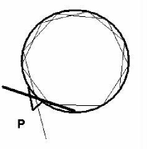
The increase of the reflection coefficient at TIR from a gainy medium can be used to develop a curious experiment for storage and amplification of light. Imagine a glass sphere with a coupler , as shown in Fig.1. The sphere has thin walls (it is also possible to use a homogeneous glass sphere) and is surrounded by an excited gas (or other active media). The ray of light, shown by the thin line, enters the glass walls through the coupler and then undergoes TIR multiple times. At every reflection the light is amplified according to the analysis in the previous Section. At the end the ray escapes the sphere, as shown by the thick line. The amplification depends on the number of the reflections and on the gain coefficient of the active medium. The number of the reflections is very sensitive to the angle of the incident ray. If the overall amplification is sufficiently high, the glass will melt into a liquid bubble with thin skin filled with the light, similar to the ball lightning [2].
We can estimate the magnitude of the light enhancement in such a sphere. Assume that for the active medium , and of the glass is real. For TEM mode, the reflection amplitude at TIR according to Eq. 18 can be written as
| (20) |
where , and the approximation is valid for small . From Eq. 20 follows that the reflection coefficient is
| (21) |
For the TH mode,
| (22) |
and
| (23) |
For estimating purposes we can assume that for both cases the light is amplified by approximately after each reflection. Therefore enhancement of the light intensity I after collisions with the wall is , where is initial intensity. The number of collisions can be represented as , where is the time between two consecutive collisions. In sphere of radius it is , where is the grazing angle at the collision point. With all these considerations we can write
| (24) |
The following analysis is used to estimate . The amplification of a laser beam along a path inside a gainy media is , where is the imaginary part of the wave number, and is called the gain coefficient. In a medium with , the gain coefficient is , where is the wavelength. For N2,CO2 gas lasers, the gain coefficient is approximately cm-1 [3]. For cm we obtain . Therefore, the number of the reflections off the interface should be larger than to obtain any practical light amplification.
In the past, many experiments were performed with the whispering gallery mode resonators (WGMR) of small dimensions ( mm) and large Q-factors (up to ) [4], where light undergoes large number total internal reflections.
Let’s imagine a sphere of cm submerged into an active medium with , and WGM with , then, according to Eq. (24), . Therefore if initial energy J, then after 20 ms the energy inside the resonator will increase enormously up to 10 MJ. The stored photons will heat and melt the resonator, but the electrostriction forces will hold the melted substance together. One can expect to see many interesting nonlinear phenomena in such systems.
Acknowledgement
3 History of submissions and rejections [7]
This paper appeared after we tried to criticize the work [5] and sent the critical paper to OPN. The main point of [5] was that reflectivity from a gainy medium at TIR is smaller than unity like reflectivity from a lossy medium. This conclusion was deduced from incorrect choice of the sign of the square root of the complex number . Dr. A.Siegmann chose , while the correct sign is , as is used in Eq. (20). The choice of sign is related to physics. With correct sign the wave function inside reflecting medium becomes , where and . This wave function exponentially decays and wave number gives a flux from reflecting gainy medium, which makes reflectivity larger than unity. With incorrect sign the wave function inside reflecting medium becomes . For Dr. A.Siegman it means that because of there is a flux toward the reflecting medium, and the gain leads to exponential grows of the field. However he did not notice that the exponential grows does not depend on gain , and since Å-1, then at distance mm from the reflecting interface the field intensity becomes (i.e. astronomically) higher than the field in the incident light. So there is a terrible violation of the energy conservation.
We tried to publish a paper in OPN with careful analysis of [5], but we were permitted to publish[6] only a list of incorrect claims in [5]. However during preparation of [6] bearing in mind the model of the ball lightning [2] we were struck by an idea that enhancement of reflectivity from a gainy media at TIR can be used for high accumulation of energy in a spherical shell and for checking the idea [2] if to put the spherical shell in a gainy medium and to send a light beam in it in a whispering gallery mode (WGM). So we submitted this paper to Optics Letters in beginning of June.
On 23 June we received a rejection from Topical Editor of Optics Letters Timothy Carrig with two referee reports.
A Referee 1
I’m sending you herewith my comments on the Ignatovich ms.
Because this is a situation where the Ignatovichs and I have a fundamental technical disagreement, I do not believe I should submit this as a formal review, or at least I should not express any opinion on whether this ms should or should not be published, leaving that to your editorial judgement and the opinions of other independent referees.
Rather I am simply expressing my views on the technical matter itself, for whatever use these may be to you. In addition, I do not think I should do this anonymously, and I am therefore copying this response to the Ignatovichs also.
The major portion of this ms (19 of the 23 equations) is devoted to a straightforward analysis of the Fresnel reflection coefficient at a dielectric interface when the lower-index reflecting medium may have either loss or gain. Although I have not checked every step of the derivation, this is in essence a ”textbook problem” and I have no reason to believe that their analytical results are not correct.
There is, however, a major disagreement between us at one step in the analysis. At a point in the general region of Eqs. (11) through (13) in the ms, one must take the square root of a certain quantity which becomes complex-valued for either a lossy or gainy reflecting medium; and one must make a choice of which sign one chooses for this square root.
For the case of a lossless or lossy medium, the conventional choice of sign is the one which makes the fields decay away exponentially with distance into the reflecting medium, a condition commonly referred as making the fields in this region evanescent. The authors of this ms believe that one should make the same choice for the case of a gainy medium, while I am convinced that the opposite choice is the physically required or physically meaningful solution in this case.
My belief is that the real physical constraint on the solution in both lossy and gainy cases is that the solution to be chosen should correspond to energy or signals which have arrived from the higher-index medium travelling on outward at a small but finite angle (as the equations indicate) into the lower-index medium, being attenuated or amplified as they go. I would note that this is in fact the condition that is met by the ”evanescent” lossy solution, where the direction of energy flow is slightly outward away from the interface, with the fields decaying in amplitude with distance as they travel outward because they are travelling in a lossy rather than a gainy medium. The same condition should also govern in the gainy case.
This solution seems to me to be mandated by simple causality, as well as giving physically reasonable answers for many other specific waveguide and other specific situations I have examined.
Whether this opinion be right or wrong, however, I must also note that what I believe to be exactly the same analysis and discussion of Fresnel reflectivity from a gainy or lossy medium as in this ms has already been presented, and the same conclusions as in this ms have been argued, in an OSA journal publication some seven years ago, i.e.
J. Fan, A. Dogariu, and L.-J. Wang, ”Amplified total internal reflection,” Opt. Expr., vol. 11, pp. 299–308, (2003).
Abstract: Totally internal reflected beams can be amplified if the lower index medium has gain. We analyze the reflection and refraction of light, and analytically derive the expression for the Goos-Hänchen shifts of a Gaussian beam incident on a lower-index medium, both active and absorptive. We examine the energy flow and the Goos-Hänchen shifts for various cases. The analytical results are consistent with the numerical results. For the TE mode, the Goos-Hänchen shift for the transmitted beam is exactly half of that of the reflected beam, resulting in a ”1/2” rule.
As always, slightly different notation and terminology has been used, but the basic problem of Fresnel reflection and its analysis is straightforward, and I believe this earlier publication and the authors’ current ms present essentially identical results. Unless the present authors can point to genuine differences between this analysis and theirs, I believe the content and conclusions of this earlier publication are essentially the same as theirs. (This ms is also referenced in my recent OPN article, with an implicit indication that I disagree in exactly similar fashion with its conclusions.)
The current authors also make brief mention of a proposed experimental test involving a sphere (or cylinder?) embedded in a dye medium. On this I would comment that a planar waveguide or cylindrical fiber would seem to me a simpler structure for such a test; that a finite-thickness gain layer is in fact very different from an unbounded gain layer for such a test in that it has two reflecting surfaces and will thus display regenerative effects; and in any case these ideas have already been discussed and even tested in several publications listed below.
Yours truly, Tony Siegman
REFERENCES
N. Periasamy and Z. Bor, ”Distributed feedback laser action in an optical fiber by evanescent field coupling,” Opt. Commun., vol. 39, pp. 298-302, (1981).
N. Periasamy, ”Evanescent wave-coupled dye laser emission in optical fibers,” Appl. Opt., vol. 21, p. 2693, (August 1982).
G. J. Pendock, H. S. Mackenzie, and F. P. Payne, ”Dye-Lasers Using Tapered Optical Fibers,” Appl. Opt., vol. 32, pp. 5236–5242, (1993).
H. Fujiwara and K. Sasaki, ”Lasing of a microsphere in dye solution,” Japan. J. Appl. Phys., vol. 38, pp. 5101–5104, (1999).
H. J. Moon, Y. T. Chough, and K. An, ”Cylindrical microcavity laser based on the evanescent-wave-coupled gain,” Phys. Rev. Lett., vol. 85, pp. 3161–3164, (2000).
Y. S. Choi, H. J. Moon, K. Y. An, S. B. Lee, J. H. Lee, and J. S. Chang, ”Ultrahigh-Q microsphere dye laser based on evanescent-wave coupling,” J. Korean Phys. Soc., vol. 39, pp. 928–931, (2001).
Our comment
On one side it is respectable that Dr. A.Siegman disclosed himself as a referee. On the other side it is seen that his main goal was to prevent publication of our paper. To do that he used the following arguments: 1) The major portion of manuscript contains nothing new comparing to textbooks, and I do not agree with authors (therefore he doesn’t agree with textbooks). 2) The proposed experiment is not interesting. It is better to check with plain wave guides or fibers. And if to speak about sphere than there is also nothing new, because there are already so many publications on micro spheres.
B Referee 2
From the report it is seen that the rejection is the main goal of the referee It is evident from the choice of words. We emphasized them in bold face without comments.
I am rejecting this paper based on my comments below.
The paper consists of two sections. Section 1 is a poor treatment of electromagnetic wave reflection and and refraction at an interface. A better treatment can be found in any standard optic textbook (e.g., Hecht). Unfortunately, it has little bearing on solving for the mode structure of a dielectric sphere. Solving for the mode structure of the resonances of a dielectric sphere in vacuum is a classic problem in electricity and magnetism, and the resulting field distributions have been known for some time (e.g., Stratton: Electricity and Magnetism.)
There are many mistakes and misleading assumptions used throughout the paper. For example, in section 1 the authors state that ”Maxwell’s equations require continuity of the electric field at the interface…” However, while the tangential component of the electric field must be continuous at the surface to satisfy the boundary conditions, there is a discontinuity in the radial component of the electric field at the dielectric boundary. The authors state that they are limiting themselves to the TE case, however, the TM modes are the interesting ones for the Whispering Gallery Modes (WGM) of microspheres, since their electric field vectors are predominantly radial.
Section 2 uses the treatment from Section 1 and applies it to the WGMs of a dielectric sphere without using the proper treatment for a sphere where the mode structure would be based on spherical Hankel functions given the boundary conditions. There are several treatments of this in the literature already (e.g., PHYSICAL REVIEW A 67, 2003 033806). It is crucial that the proper mode structure be accounted for with the proper boundary condition, especially if it is to be applied in a case where gain will be present. In that case, there will also be time dependencies that may need to be addressed for a proper treatment.
The only new items in the entire paper consist of a few sentences of conjecture on the amplification of light using the WGMs of a dielectric sphere immersed in a gain medium. This conjecture is not based on a proper treatment of the electromagnetic modes, and there is no testable prediction of the effect. The paper amounts to a comment on an idea and needs serious expansion with a far more careful treatment before it could possibly be considered for any peer reviewed journal.
C Our appeal
Dear Dr. Carrig,
We would like to appeal your decision due to the reasons listed below.
The Referee 1, Dr. A.Siegman, is not suitable for reviewing our paper. As indicated by our earlier email (included at the end of this email) to you as well as by Dr. A.Siegman himself, his review represents a conflict of interests. We wrote our paper after reading Dr. Siegman’s article in OPN, and we think his views are erroneous down to the textbook optics level. Obviously, he does not agree with our point of view and therefore is not interested in any publications that would criticize his article. Therefore, we think that Dr. Siegman’s comments should not be counted toward the publication decision, and the manuscript should be resubmitted to another referee.
We disagree with the decision of Referee 2. He completely misunderstood our article. We prove this point by addressing the Referee’s review as follows.
1) Section 1 is a poor treatment of electromagnetic wave reflection.
It is unclear what the Referee 2 means by ”poor treatment”. Is it a wrong treatment? Absolutely not, it is in fact a textbook treatment of the electromagnetic wave reflection. Does the Referee 2 thinks that textbooks are poor? Such emotional statement does not carry any substantiality or significance.
2) Unfortunately, it has little bearing on solving for the mode structure of a dielectric sphere.
Judging by the other parts of the review, the Referee’s expertise lays in microspheres. It indeed would be important to reference the electromagnetic distribution and its effects in a microsphere if that was the case. However, in our manuscript, the radius of the sphere is supposed to be much larger than the light wave length, therefore every reflection can be treated in plane geometry approximation. The Referee appears to have overlooked this important detail.
3) There are many mistakes and misleading assumptions
While this statement would be very important in making publication decision, it is not backed by any proof. The Referee 2 does not point out where in the manuscript he saw the mistakes and misleading assumptions. His only hint at a mistake is wrong - see the next point.
4)Authors state that ”Maxwell’s equations require continuity of the electric field at the interface…” However, while the tangential component of the electric field must be continuous at the surface to satisfy the boundary conditions, there is a discontinuity in the radial component
The Referee 2 is correct - the normal component has discontinuity. However we are talking about the which is the tangential field and does not contain the normal component. Referee 2 overlooked this important detail and made a completely correct statement appear as incorrect.
5) The authors state that they are limiting themselves to the TE case, however, the TM modes are the interesting ones for the Whispering Gallery Modes (WGM) of microspheres, since their electric field vectors are predominantly radial.
See the point 2 (we do not consider microspheres). Also, it is widely accepted in science to consider only one case, when other cases have similar outcomes for simplicity, clarity and space-saving purposes, especially when the manuscript pages are limited. We are not sure why the Referee 2 holds us at fault for it.
6) Section 2 uses the treatment from Section 1 and applies it to the WGMs of a dielectric sphere without using the proper treatment for a sphere where the mode structure would be based on spherical Hankel functions given the boundary conditions. There are several treatments of this in the literature already (e.g., PHYSICAL REVIEW A 67, 2003 033806). It is crucial that the proper mode structure be accounted for with the proper boundary condition, especially if it is to be applied in a case where gain will be present.
Again, see the point 2 - we do not consider microspheres.
6) In that case, there will also be time dependencies that may need to be addressed for a proper treatment.
The time dependence is a primitive exponential (harmonic). We do not anticipate any other time dependencies in our configuration. Again, the Referee thinks of microspheres.
7) The only new items in the entire paper consist of a few sentences of conjecture on the amplification of light using the WGMs of a dielectric sphere immersed in a gain medium.
The use of the word ”only” in regards to new items is an emotional belittling of our ideas. We regard this comment as Referee’s acknowledgement of the novelty of the article, but his view of its general impact as subjective. These ideas may not epitomize a breakthrough in science, however they provides direction for further scientific research, just like the majority of peer-review articles do.
9) there is no testable prediction of the effect.
While this particular Referee does not have an idea for an experimental testing of the effects that we predict, it does not mean that the ideas are not worth publishing. First, with such attitude, for example, none of the string theory articles would ever be published. Second, there are many other scientists who read OL and it is our hope and goal that someone will become interested and will have an idea to attempt the experimentally implementation of the proposed configuration.
The Referee 2 hasn’t found any mistakes in our article. He even acknowledges that our article has new material, however immediately belittles it. This new material is the main idea behind our paper, but the referee fails to recognize it instead of concentrating on other parts of the manuscript in his criticism from the erroneous microsphere standpoint. We think that the review by Referee 2 also cannot be used.
We would like to modify the article to emphasize important points to avoid misunderstandings similar to Reviewer 2 and resubmit the manuscript.
The letter we sent you in response to Dr. Siegman’s email:
Dear Dr. Carrig,
We echo Dr. Siegman’s concern that it may be advantageous to forward our manuscript to a third party since our manuscript originally stems from the fundamental disagreement with Dr. Siegman’s views. We are sorry that we have not made it clear during submission that Dr. Siegman may not be an appropriate choice for a reviewer. We appreciate that Dr. Siegman recognized this conflict of interests and included us in his reply.
We were taken aback when we saw Dr. Siegman’s paper in OPN, and we wanted to remind the scientific community how to calculate Fresnel reflection amplitudes, which is discussed in many text books and additionally in the paper Opt. Expr., vol. 11, pp. 299–308, (2003) cited here by Dr. A.Siegman. We also discussed why the sign of square root is uniquely defined by physical reasons. If Dr. A.Siegman were right, electric field in the gainy medium just 1 cm away from interface would be 4 orders of magnitude larger (we mistaken here, look above: it will be more than 800 orders of magnitude) than in the total internal reflection field, notwithstanding how small is the gain.
Our main goal for submitting the manuscript was to propose and motivate the laser physicists to make an experiment with a spherical beam trap where the light beam is strongly amplified after many total internal reflections. Such amplification then melts the sphere and transforms it to a liquid drop, with physical processes inside becoming very similar to a ball lightning. Planar wave guides or cylindrical fibers are unfortunately not appropriate for this goal.
D Response from the editor
After reading your appeal and taking it into consideration, I have decided to stand by my original decision. Despite your a priori disagreement with Prof. Siegman, who was cited in your references, he is well-respected in the field and is a reasonable choice as a reviewer. The paper was also sent to a second independent reviewer. This reviewer is also a scientist with a very strong reputation. This reviewer also recommended rejection, albeit for somewhat different reasons. I consider these two reviews adequate for adjudicating the manuscript.
E Reply to the editor
Dear Dr. Carrig,
Is there a next step in the appeal process, where your decision can be reviewed by another editor? There has to be a reason why in the judicial system appeals go to an appellate court, different from the court that decided the original verdict.
It is very unfortunate that modern science puts reputation above reason. As a recent graduate I do not stand a chance in any debate, however solid my arguments may be. Such approach in no way stimulates progress.
Sincerely, Filipp Ignatovich
References
- [1] L. D. Landau, E. M. Lifshitz and L. P. Pitaevskii, Electrodynamics of Continuous Media (Elsevier Butterworth-Heinemann, 2004)
- [2] V.K.Ignatovich, “The Ball Lightning,” Las. Phys. 2, 991–996 (1992).
- [3] E.W.McDaniel, W.L.Higham (ed-s), Applied atomic collision physics (Academic Press, 1982) Volume 3, Chapter 8, Figure 2.
- [4] J. U. Fürst, D. V. Strekalov, D. Elser, M. Lassen, U. L. Andersen, C. Marquardt, and G. Leuchs, “Naturally Phase-Matched Second-Harmonic Generation in a Whispering-Gallery-Mode Resonator,” Phys. Rev. Lett. 104, 153901 (2010).
- [5] A.E. Siegman, “Fresnel Refl ection, Lenserf Reflection and Evanescent Gain,” OPN 21, 38–45 (2010).
- [6] F.V. Ignatovich and V.K. Ignatovich, “On Fresnel Reflection and Evanescent Gain,” OPN 21, 6 (2010).
-
[7]
https://pin.jinr.ru/pin/pin?c=top&pp=29345&tm=
1277729437266